K6610503220VHF FM Handheld Transceiver
Yaesu Musen Co., Ltd.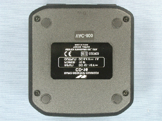
Click to zoom
Application Details
- Equipment Class
- TNF - Licensed Non-Broadcast Transmitter Held to Face
- Date of Grant
- Feb 08, 2004
- Application Purpose
- Original Equipment
- Date of Application
- Dec 03, 2003
- Equipment Note
- VHF FM Handheld Transceiver
- Frequency Range
- 146.00000000 - 174.00000000
- Company
- Yaesu Musen Co., Ltd.
- Country
- Japan
Documents & Files
Document Text
Text extracted from the exhibit documents filed with the FCC. Open a document above to read the original.
Users Manual
VX410/420 Series Operating Manual 1/9 Vertex Standard Co., Ltd. VX-410/420 Series Operating Manual Important Notice! FCC RF Exposure Compliance Requirements for Occupational Use Only: This Radio has been tested and complies with the Federal Communications Commission (FCC) RF exposure limits for Occupational Use/Controlled exposure environment. In addition, it complies with the following Standards and Guidelines: FCC 96-326, Guidelines for Evaluating the Environmental Effects of Radio-Frequency Radiation. FCC OET Bulletin 65 Edition 97-01 (1997) Supplement C, Evaluating Compliance with FCC Guidelines for Human Exposure to Radio Frequency Electromagnetic Fields. ANSI/IEEE C95.1-1992, IEEE Standard for Safety Levels with Respect to Human Exposure to Radio Frequency Electromagnetic Fields, 3kHz to 300 GHz. ANSI/IEEE C95.3-1992, IEEE Recommended Practice for the Measurement of Potentially Hazardous Electromagnetic Fields-RF and Microwave. This radio is NOT approved for use by the general population in an uncontrolled environment. This radio is restricted to occupational use, work related operations only where the radio operator must have the knowledge to control its RF exposure conditions. When transmitting, hold the radio in a vertical position with its microphone 1 to 2 inches (2.5 to 5 cm) away from your mouth and keep the antenna at least 1 inch (2.5cm) away from your head and body. The radio must be used with a maximum operating duty cycle not exceeding 50 %, in typical Push-to-Talk (PTT) configurations. DO NOT transmit for more than 50 % of total radio use time (50 % duty cycle). Transmitting more than 50 % of the time can cause FCC RF exposure compliance requirements to be exceeded. The radio is transmitting when the red LED on the top of the radio is illuminated. You can cause the radio to transmit by pressing the PTT button. DO NOT transmit when the radio is used in Body Worn configuration with the following accessory: belt-clip (Parts # CP7064001). It must be used ONLY for (1) there is a 4 cm distance from the body during transmitting, (2) monitoring purposes, using the speaker only and (3) for carrying purposes. Always use Vertex Standard authorized accessories. VX410/420 Series Operating Manual 2/9 Vertex Standard Co., Ltd. Controls & Connectors ・ LED Indicator Glows Green: Monitor on Blinks Green: Busy Channel (or SQL off) Glows Red: Transmit Blinks Red: Battery Voltage is low Blinks Yellow: Receiving a Selective Call ・ Antenna Jack ・ PTT(Push To Talk)Switch ・ Side1 key(Case side) ・ Side2 key(Case side) ・ CH(Channel) Selector ・ VOL/PWR knob ・ LCD (VX-427 only) ・ A Key (VX-427 only) with 16 keys ・ B Key (VX-427 only) with 16 keys ・ C Key (VX-427 only) with 16 keys ・ D Key (VX-427 only) with 16 keys ・ MIC/SP Jack (External Mic/Earphone) ・ Speaker ・ Internal Microphone ・ Battery Pack Latch Before You Begin Battery Pack Installation and Removal ・ To install the battery, hold the transceiver with your left hand, so your palm is over the speaker and your thumb is on the top of the belt clip. Insert the battery pack into the battery compartment on the back of the radio while titling the Belt Clip outward, then close the Battery Pack Latch until it locks in place with a “Click”. ・ To remove the battery, turn the radio off and remove protective cases. Open the Battery Pack Latch on the bottom of the radio, and then slide the battery downward and out from the radio while unfolding the Belt Clip. Caution!: Do not attempt to open any of the rechargeable Ni-Cd packs, as they could explode if accidentally short-circuited. Low Battery Indication ・ As the battery discharges during use, the voltage gradually becomes lower. When the battery voltage reaches 6.3 Volts, substitute a freshly charged battery and recharge the depleted pack. The TX/BUSY indicator on the top of the radio will blink red when the battery voltage is low. ・ Avoid recharging Ni-Cd batteries often with little use between charges, as this can degrade the charge capacity. We recommend that you carry an extra, fully-charged pack with you so the operational battery may be used until depletion (this “deep cycling” technique promotes better long-term battery capacity) VX410/420 Series Operating Manual 3/9 Vertex Standard Co., Ltd. Operation Preliminary Steps ・ Install a charged battery pack onto the transceiver, as described previously. ・ Screw the supplied antenna onto the Antenna jack. Never attempt to operate this transceiver without an antenna connected. ・ If you have a Speaker/Microphone, we recommend that it not be connected until you are familiar with the basic operation of the VX-417/427. Operation Quick Start ・ To turn the top panel’s [VOL/PWR] knob clockwise to turn on the radio on. ・ Turn the top panel’s [CH] selector knob to choose the desired operating channel. ・ Rotate the [VOL/PWR] knob to set the volume level. If no signal is present, press and hold the [MONOTOR] (need select by the key config on program) key more than 1 seconds; background noise will now be heard, and you may use this to set the [VOL/PWR] knob for the desired audio level. ・ Press and hold the [MONITOR] key more than 1 seconds (or press the [MONITOR] key twice) to quiet the noise and resume normal (quiet) monitoring. ・ To transmit, press and hold the [PTT] switch. Speak into the microphone area of the front panel grill (lower left-hand corner) in a normal voice level. To return to the Receive mode, release the [PTT] switch. ・ If a Speaker/Microphone is available, remove the plastic cap and its two mounting screws from the right side of the transceiver, than insert the plug from the Speaker/Microphone into the [MIC/SP] jack; secure the plug using the screw supplied with the Speaker/Microphone. Hold the speaker grille up next to your ear while receiving. To transmit, press the [PTT] switch on the Speaker/Microphone, just as you would on the main transceiver’s body. Note: Save the original plastic cap and its mounting screws. They shoul…
Text truncated - open the document above for the full version.
Users Manual
Vertex Standard Co., Ltd. SAFETY TRANING INFORMATION This Radio has been tested and complies with the Federal Communications Commission (FCC) RF exposure limits for Occupational Use/Controlled exposure environment. In addition, it complies with the following Standards and Guidelines: - FCC 96-326, Guidelines for Evaluating the Environmental Effects of Radio-Frequency Radiation. - FCC OET Bulletin 65 Edition 97-01 (1997) Supplement C, Evaluating Compliance with FCC Guidelines for Human Exposure to Radio Frequency Electromagnetic Fields. - ANSI/IEEE C95.1-1992, IEEE Standard for Safety Levels with Respect to Human Exposure to Radio Frequency Electromagnetic Fields, 3kHz to 300 GHz. - ANSI/IEEE C95.3-1992, IEEE Recommended Practice for the Measurement of Potentially Hazardous Electromagnetic Fields-RF and Microwave. WARNING: This radio generates RF electromagnetic energy during transmit mode. This radio is designed for and classified as Occupational Use Only, meaning it must be used only during the course of employment by individuals aware of the hazards, and the ways to minimize such hazards. This radio is not intended for use by the General Population in an uncontrolled environment. CAUTION: To ensure that your expose to RF electromagnetic energy is within the FCC allowable limits for occupational use, always adhere to the following guidelines: - This radio is NOT approved for use by the general population in an uncontrolled environment. This radio is restricted to occupational use, work related operations only where the radio operator must have the knowledge to control its RF exposure conditions. - When transmitting, hold the radio in a vertical position with its microphone 1 to 2 inches (2.5 to 5 cm) away from your mouth and keep the antenna at least 1 inch (2.5cm) away from your head and body. - The radio must be used with a maximum operating duty cycle not exceeding 50 %, in typical Push-to-Talk (PTT) configurations. DO NOT transmit for more than 50 % of total radio use time (50 % duty cycle). Transmitting more than 50 % of the time can cause FCC RF exposure compliance requirements to be exceeded. The radio is transmitting when the red LED on the top of the radio is illuminated. You can cause the radio to transmit by pressing the PTT button. - DO NOT transmit when the radio is used in Body Worn configuration with the following accessory: belt-clip (Parts # CP7064001). It must be used ONLY for (1) there is a 4 cm distance from the body during transmitting, (2) monitoring purposes, using the speaker only and (3) for carrying purposes. - Always use Vertex Standard authorized accessories. The information listed above provides the user with the information needed to make him or her aware of RF exposure, and what to do to assure that this radio operates with the FCC RF exposure limits of this radio. Electromagnetic Interference/Compatibility During transmissions, this radio generates RF energy that can possibly cause interference with other devices or systems. To avoid such interference, turn off the radio in areas where signs are posted to do so. Do not operate the transmitter in areas that are sensitive to electromagnetic radiation such as hospitals, health care facilities, aircraft, and blasting sites. Vertex Standard Co., Ltd. FCC LICENSE INFORMATION This radio operates on communications frequencies which are subject to FCC (Federal Communications Commission) Rules and Regulations. FCC Rules require that all operators using Private Land Mobile radio frequencies obtain a radio license before operating their equipment.
Users Manual
VX410/420 Series Operating Manual 1/9 Vertex Standard Co., Ltd. VX-410/420 Series Operating Manual Important Notice! FCC RF Exposure Compliance Requirements for Occupational Use Only: This Radio has been tested and complies with the Federal Communications Commission (FCC) RF exposure limits for Occupational Use/Controlled exposure environment. In addition, it complies with the following Standards and Guidelines: FCC 96-326, Guidelines for Evaluating the Environmental Effects of Radio-Frequency Radiation. FCC OET Bulletin 65 Edition 97-01 (1997) Supplement C, Evaluating Compliance with FCC Guidelines for Human Exposure to Radio Frequency Electromagnetic Fields. ANSI/IEEE C95.1-1992, IEEE Standard for Safety Levels with Respect to Human Exposure to Radio Frequency Electromagnetic Fields, 3kHz to 300 GHz. ANSI/IEEE C95.3-1992, IEEE Recommended Practice for the Measurement of Potentially Hazardous Electromagnetic Fields-RF and Microwave. This radio is NOT approved for use by the general population in an uncontrolled environment. This radio is restricted to occupational use, work related operations only where the radio operator must have the knowledge to control its RF exposure conditions. When transmitting, hold the radio in a vertical position with its microphone 1 to 2 inches (2.5 to 5 cm) away from your mouth and keep the antenna at least 1 inch (2.5cm) away from your head and body. The radio must be used with a maximum operating duty cycle not exceeding 50 %, in typical Push-to-Talk (PTT) configurations. DO NOT transmit for more than 50 % of total radio use time (50 % duty cycle). Transmitting more than 50 % of the time can cause FCC RF exposure compliance requirements to be exceeded. The radio is transmitting when the red LED on the top of the radio is illuminated. You can cause the radio to transmit by pressing the PTT button. DO NOT transmit when the radio is used in Body Worn configuration with the following accessory: belt-clip (Parts # CP7064001). It must be used ONLY for (1) there is a 4 cm distance from the body during transmitting, (2) monitoring purposes, using the speaker only and (3) for carrying purposes. Always use Vertex Standard authorized accessories.
Users Manual
VX410/420 Series Operating Manual 1/10 Vertex Standard Co., Ltd. VX-410/420 Series Operating Manual SAFETY TRANING INFORMATION This Radio has been tested and complies with the Federal Communications Commission (FCC) RF exposure limits for Occupational Use/Controlled exposure environment. In addition, it complies with the following Standards and Guidelines: - FCC 96-326, Guidelines for Evaluating the Environmental Effects of Radio-Frequency Radiation. - FCC OET Bulletin 65 Edition 97-01 (1997) Supplement C, Evaluating Compliance with FCC Guidelines for Human Exposure to Radio Frequency Electromagnetic Fields. - ANSI/IEEE C95.1-1992, IEEE Standard for Safety Levels with Respect to Human Exposure to Radio Frequency Electromagnetic Fields, 3kHz to 300 GHz. - ANSI/IEEE C95.3-1992, IEEE Recommended Practice for the Measurement of Potentially Hazardous Electromagnetic Fields-RF and Microwave. WARNING: This radio generates RF electromagnetic energy during transmit mode. This radio is designed for and classified as Occupational Use Only, meaning it must be used only during the course of employment by individuals aware of the hazards, and the ways to minimize such hazards. This radio is not intended for use by the General Population in an uncontrolled environment. CAUTION: To ensure that your expose to RF electromagnetic energy is within the FCC allowable limits for occupational use, always adhere to the following guidelines: - This radio is NOT approved for use by the general population in an uncontrolled environment. This radio is restricted to occupational use, work related operations only where the radio operator must have the knowledge to control its RF exposure conditions. - When transmitting, hold the radio in a vertical position with its microphone 1 to 2 inches (2.5 to 5 cm) away from your mouth and keep the antenna at least 1 inch (2.5cm) away from your head and body. - The radio must be used with a maximum operating duty cycle not exceeding 50 %, in typical Push-to-Talk (PTT) configurations. DO NOT transmit for more than 50 % of total radio use time (50 % duty cycle). Transmitting more than 50 % of the time can cause FCC RF exposure compliance requirements to be exceeded. The radio is transmitting when the red LED on the top of the radio is illuminated. You can cause the radio to transmit by pressing the PTT button. - DO NOT transmit when the radio is used in Body Worn configuration with the following accessory: belt-clip (Parts # CP7064001). It must be used ONLY for (1) there is a 4 cm distance from the body during transmitting, (2) monitoring purposes, using the speaker only and (3) for carrying purposes. - Always use Vertex Standard authorized accessories. The information listed above provides the user with the information needed to make him or her aware of RF exposure, and what to do to assure that this radio operates with the FCC RF exposure limits of this radio. Electromagnetic Interference/Compatibility During transmissions, this radio generates RF energy that can possibly cause interference with other devices or systems. To avoid such interference, turn off the radio in areas where signs are posted to do so. Do not operate the transmitter in areas that are sensitive to electromagnetic radiation such as hospitals, health care facilities, aircraft, and blasting sites. VX410/420 Series Operating Manual 2/10 Vertex Standard Co., Ltd. FCC LICENSE INFORMATION This radio operates on communications frequencies which are subject to FCC (Federal Communications Commission) Rules and Regulations. FCC Rules require that all operators using Private Land Mobile radio frequencies obtain a radio license before operating their equipment. VX410/420 Series Operating Manual 3/10 Vertex Standard Co., Ltd. Controls & Connectors ・ LED Indicator Glows Green: Monitor on Blinks Green: Busy Channel (or SQL off) Glows Red: Transmit Blinks Red: Battery Voltage is low Blinks Yellow: Receiving a Selective Call ・ Antenna Jack ・ P T T ( P u s h To Ta l k ) S w i t c h ・ Side1 key(Case side) ・ Side2 key(Case side) ・ CH(Channel) Selector ・ VOL/PWR knob ・ LCD (VX-427 only) ・ A Key (VX-427 only) with 16 keys ・ B Key (VX-427 only) with 16 keys ・ C Key (VX-427 only) with 16 keys ・ D Key (VX-427 only) with 16 keys ・ MIC/SP Jack (External Mic/Earphone) ・ Speaker ・ Internal Microphone ・ Battery Pack Latch Before You Begin Battery Pack Installation and Removal ・ To install the battery, hold the transceiver with your left hand, so your palm is over the speaker and your thumb is on the top of the belt clip. Insert the battery pack into the battery compartment on the back of the radio while titling the Belt Clip outward, then close the Battery Pack Latch until it locks in place with a “Click”. ・ To remove the battery, turn the radio off and remove protective cases. Open the Battery Pack Latch on the bottom of the radio, and then slide the battery downward and out from the radio while unfolding the Belt Clip. Caution!: Do not attempt to open any of the rechargeable Ni-Cd packs, as they could explode if accidentally short-circuited. Low Battery Indication ・ As the battery discharges during use, the voltage gradually becomes lower. When the battery voltage reaches 6.3 Volts, substitute a freshly charged battery and recharge the depleted pack. The TX/BUSY indicator on the top of the radio will blink red when the battery voltage is low. ・ Avoid recharging Ni-Cd batteries often with little use between charges, as this can degrade the charge capacity. We recommend that you carry an extra, fully-charged pack with you so the operational battery may be used until depletion (this “deep cycling” technique promotes better long-term battery capacity) VX410/420 Series Operating Manual 4/10 Vertex Standard Co., Ltd. Operation Preliminary Steps ・ Install a charged battery pack onto the transceiver, as described previously. ・ Screw the supplied antenna onto the Antenna jack. Never attempt to operate this transceiver without an antenna connect…
Text truncated - open the document above for the full version.
Cover Letter(s)
February 5, 2004 FCC: Stan Lyles Applicant: Vertex Standard Co., Ltd. Equipment: FCC ID: K6610503220, EA654860 Reference: Correspondence Number 26317 Stan: Thanks for your speedy response. 1) Part 95 will be deleted. This is your authorization to remove reference to part 95 from the Form 731. As you can appreciate, all manufacturers want as many of the Rule Parts certified for their products. They just want to see any deletion in writing. 2) The following information will be added to the manual: “This radio is supplied with 3 antennas, marked ‘A’, ‘B’, and ‘C’, which must be connected for low frequency (146-155 MHz), medium frequency (155-165 MHz) and high frequency (165-174 MHz) respectively to comply with the FCC R.F. Exposure requirement for all R.F. Output Powers.” 3) Sentence has been updated as follows: “You can cause the radio to transmit by pressing the PTT button or by using the VOX headset, model VC-25”. Your early attention to this submission will be most appreciated. Thank you. Sincerely yours, Morton Flom, P. Eng.
External Photos
FCC ID: K6610503220 IC ID: 511B-10503220 Vertex Standard Co., Ltd. Front view (VX-414) with Antenna Front view (VX-414) without Antenna FCC ID: K6610503220 IC ID: 511B-10503220 Vertex Standard Co., Ltd. Front view (VX-424) with Antenna Front view (VX-424) without Antenna FCC ID: K6610503220 IC ID: 511B-10503220 Vertex Standard Co., Ltd. Rear view with Battery Pack Rear view without Battery Pack FCC ID: K6610503220 IC ID: 511B-10503220 Vertex Standard Co., Ltd. Left view (VX-414) Right view (VX-414) FCC ID: K6610503220 IC ID: 511B-10503220 Vertex Standard Co., Ltd. Left view (VX-424) Right view (VX-424) FCC ID: K6610503220 IC ID: 511B-10503220 Vertex Standard Co., Ltd. Top view Bottom view (VX-414) FCC ID: K6610503220 IC ID: 511B-10503220 Vertex Standard Co., Ltd. Bottom view (VX-424) Top of Battery Charger FCC ID: K6610503220 IC ID: 511B-10503220 Vertex Standard Co., Ltd. Bottom of Battery Charger Top of AC Adapter FCC ID: K6610503220 IC ID: 511B-10503220 Vertex Standard Co., Ltd. Bottom of AC Adapter Front of Microphone FCC ID: K6610503220 IC ID: 511B-10503220 Vertex Standard Co., Ltd. Back of Microphone Antenna
ID Label/Location Info
VX-414-2-5 / VX-424-2-5VX-414-2-5 / VX-424-2-5 LABEL DRAWINGLABEL DRAWING Vertex Standard Co., Ltd.Vertex Standard Co., Ltd. ID / Part 15.19 and CAUTION drawings ID drawing Part 15.19 and CAUTION drawings Label location ! ! Device restricted to occupational use to satisfy FCC RF exposure compliance. See owner's manual for specific operating requirement CAUTION This device complies with part 15 of the FCC Rules. Operation is subject to the condition that this device does not cause harmful interference. VX-414-2-5 K6610503220 511B-10503220 4909959000000 VX-424-2-5 K6610503220 511B-10503220 4909959000000
Internal Photos
FCC ID: K6610503220 IC ID: 511B-10503220 Vertex Standard Co., Ltd. Removed Front Panel Side-A of MAIN-UNIT with LCD FCC ID: K6610503220 IC ID: 511B-10503220 Vertex Standard Co., Ltd. Side-A of MAIN-UNIT without LCD Side-B of MAIN-UNIT with shield case FCC ID: K6610503220 IC ID: 511B-10503220 Vertex Standard Co., Ltd. Side-B of MAIN-UNIT without shield case Front of LCD (for VX-424) FCC ID: K6610503220 IC ID: 511B-10503220 Vertex Standard Co., Ltd. Back of LCD (for VX-424) Inside of front panel (VX-414) FCC ID: K6610503220 IC ID: 511B-10503220 Vertex Standard Co., Ltd. Inside of front panel (VX-424) Inside of chassis FCC ID: K6610503220 IC ID: 511B-10503220 Vertex Standard Co., Ltd. Inside top of Battery Charger Inside Bottom of Battery Charger with PWB FCC ID: K6610503220 IC ID: 511B-10503220 Vertex Standard Co., Ltd. Inside Bottom of Battery Charger without PWB Component Side of Charger PWB FCC ID: K6610503220 IC ID: 511B-10503220 Vertex Standard Co., Ltd. Solder Side of Charger PWB Inside of microphone (1) FCC ID: K6610503220 IC ID: 511B-10503220 Vertex Standard Co., Ltd. Inside of microphone (2)
Operational Description
FCC ID: K6610503220 IC ID: 511B-10503220 Circuit Description 1/3 Vertex Standard Co., Ltd. VX-414/424 Circuit Description 1. Receive Signal Path Incoming RF from the antenna jack is delivered to the RF Unit and passes through a low- pass filter consisting of coils L1002, and L1003, capacitors C1001, C1002, C1021, C1024, C1025, C1026, and C1027, and antenna switching diode D1004. Signals within the frequency range of the transceiver enter a Varactor-tuned band-pass filter consisting of coils L1012 and L1015, capacitors C1058, C1059, C1085, C1118 and C1119, and diodes D1007, D1008, D1009 and D1010, then amplified by Q1019 and enter a Varactor-tuned band-pass filter consisting of coils L1020 and L1025, capacitors C1053, C1054, C1056, C1180 and C1181, and diodes D1012, D1013, D1016, D1051 and D1052, before first mixing by Q1029. Buffered output from the VCO is amplified by Q1026 to provide a pure first local signal between 196.85 and 224.85 MHz for injection to the first mixer Q1029. The 50.85 MHz first mixer product then passes through monolithic crystal filter XF1001 (5.5 kHz BW) to strip away all but the desired signal, which is then amplified by Q1041. The amplified first IF signal is applied to FM IF subsystem IC Q1048, which contains the second mixer, second local oscillator, limited amplifier, noise amplifier, and RSSI amplifier. A second local signal is produced from the PLL reference/second local oscillator of X1002 (TCXO, 16.80 MHz). The 16.80 MHz reference signal is tripled by Q1048 and capacitor C1251, Coil L1042, then resulting the 50.40 MHz second local signal delivered to mixer section of Q1048 which produce the 450 kHz second IF mixed with the first IF signal. The second IF then passes through the ceramic filter CF1001 (on “ Narrow” channels) or CF1002 (on “Wide” and ”Narrow” channels) to strip away unwanted mixer products, and is then applied to the limited amplifier in Q1048, which removes amplitude variations in the 450kHz IF, before detection of the speech by the ceramic discriminator CD1001. 2.Audio Amplifier The demodulated audio signal from the Q1048 passes through a low-pass filter and High-pass filter to the Voice Scrambler Unit when the optional Scrambler Unit is installed, then applied to the de-emphasis Q1021 via the dummy unit. The audio signal is applied to the expander Q1021 or switch circuit consisting of Q1009 and Q1011. The output from Q1021 or Q 1011 passes through the audio volume and the audio power amplifier Q1005, providing up to 500 mW of audio power to the 4 Ω loudspeaker. 3. Squelch Control The squelch circuitry consists of a noise amplifier and band-pass filter and noise detector within Q1048. When no carrier received, noise at the output of the detector stage in Q1048 is amplified and band-pass filtered by the noise amplifier section of Q1048 and the network between pins 7 and 8, and then rectified by detection circuit in Q1048. The resulting DC squelch control voltage is passed to pin 19 of the microprocessor Q1047. If no carrier is received, this signal causes pin 19 of Q1047 to go high and pin 30 to go high. Pin 35 signals Q1006 to disable the supply voltage to the audio amplifier Q1005, while pin 30 hold the green (Busy) half of the LED off, when pin 35 is high and pin 30 is high. Thus, the microprocessor blocks output from the audio amplifier, and silences the receiver, while no signal is being received (and during transmission, as well). When a carrier appears at the discriminator, noise is removed from the output, causing pin 19 of Q1047 to go low and the microprocessor to activate the “Busy” LED via Q1047. The microprocessor then checks for CTCSS or CDCSS code squelch information, if enabled. If not transmitting and CTCSS or CDCSS is not activated, or if the received tone or code matches that programmed, allows audio to pass through the audio amplifier Q1005 to the loudspeaker by enabling the supply voltage to it via Q1048. FCC ID: K6610503220 IC ID: 511B-10503220 Circuit Description 2/3 Vertex Standard Co., Ltd. 4. Transmit Signal Path The speech input from the microphone MC1001 passes through the audio amplifier Q1021 to Q1015, which is adjusted the microphone gain. The adjusted audio is applied to the compounder Q1010, which is compressed the speech signal according to the control command from the microprocessor Q1047. The compressed speech signal passes through the dummy unit and pre-emphasis circuit to Q1021, which contains the low-pass filter, Voice Scrambler selector, and high-pass filter. The output from Q1021 is applied to the AF Mute gate Q1055, then return to Q1021, which contains the limiter amplifier, Low pass filter and audio amplifier. The filtered audio signal is applied to Q1015 which is adjusted the audio level, then is applied to varactor diode D1017, which frequency modulates the VCO Q1033. A portion of the audio signal from Q1015 is applied to TCXO X1002. The processed audio may then be mixed with a CTCSS tone generated by Q1047 for frequency modulation of the PLL carrier (up to ±5 kHz from the unmodulated carrier) at the transmitting frequency. If a CDCSS code is enabled for transmission, the code is generated by microprocessor Q1047 and delivered to X1002 (TCXO, 16.80 MHz) for CDCSS modulating. The modulated signal from the VCO Q1033 is buffered by Q1026. The low-level transmit signal is then passes through the TX switching diode D1048 to the driver amplifier Q1020 and Q1014, then amplified transmit signal is applied to the final amplifier Q1008 up to 5 watts output power. The transmit signal then passes through the antenna switch D1004 and is low-pass filtered to suppress harmonic spurious radiation before delivery to the antenna. 4-1 Automatic Transmit Power Control Current from the final amplifier is sampled by R1015, R1038 and R1040, and is rectified by Q1003. The resulting DC is fed back through Q1002 to the drive amplifier Q1014 and final amplifier Q1008, for control of the power output. The microprocessor selec…
Text truncated - open the document above for the full version.
Parts List/Tune Up Info
1/2 FCC ID: K6610503220 IC ID: 511B-10503220 Component Applications Address Device nameDescriptionApplication VX-414-2-5/VX-424-2-5 D 1001 Diode 1SS400G Side Key1 Switch D 1002 Diode 1SS400G Side Key2 Switch D 1003 Not Used D 1004 Diode RLS135 Antenna Switch D 1005 Diode HSU277 TX/RX Switch D 1006 Diode HSU277 TX/RX Switch D 1007 Varactor Diode HVD358B RX Tuning D 1008 Varactor Diode HVD358B RX Tuning D 1009 Varactor Diode HVD358B RX Tuning D 1010 Varactor Diode HVD358B RX Tuning D 1011 Not Used D 1012 Varactor Diode HVD358B RX Tuning D 1013 Varactor Diode HVD358B RX Tuning D 1014 Diode HSC277 RX Switch D 1015 Diode 1SS400G Speed Up D 1016 Varactor Diode HVD358B RX Tuning D 1017 Varactor Diode HVD350B Modulation D 1018 Diode 1SS400G Channel Switch D 1019 Diode 1SS400G Switch D 1020 Dual Diode DA221 Protect D 1021 Varactor Diode HVD372BRX VCO Frequency Control D 1022 Varactor Diode HVD372BRX VCO Frequency Control D 1023 Varactor Diode HVD372BRX VCO Frequency Control D 1024 Varactor Diode HVD372BRX VCO Frequency Control D 1025 Diode 1SS400G Channel Switch D 1026 Diode 1SS400G Channel Switch D 1027 LED LNJ808K8SRA Indicator D 1028 LED LNJ808K8SRA Indicator D 1029 LED LNJ808K8SRA Indicator D 1030 LED LNJ808K8SRA Indicator D 1031 Diode 1SS400G Key Switch D 1032 Diode 1SS400G Key Switch D 1033 Diode 1SS400G Key Switch D 1034 Diode 1SS400G Key Switch D 1035 Diode 1SS400G Speed Up D 1036 Dual Diode DA221 IF Limit D 1037 Varactor Diode HVD358B TX VCO Frequency Control D 1038 Varactor Diode HVD358B TX VCO Frequency Control D 1039 LED 12-22SURSYGC/S530-A2 Indicator D 1040 LEDOU1008A Indicator D 1041 Not Used D 1042 Diode 1SS400G Detector D 1043 Diode 1SS400G Protect D 1044 Dual Diode DAN222 Wide/Narrow Switch D 1045 Dual Diode DAN222 Wide/Narrow Switch D 1046 Not Used D 1047 Diode 1SS400G Channel Switch D 1048 Diode HSC277 TX Switch D 1049 Diode 1SS400G Protect D 1050 Not Used D 1051 Varactor Diode HVD358B RX Tuning D 1052 Varactor Diode HVD358B RX Tuning D 1053 Diode 1SS400G Protect D 1054 Surge Absorber TVSF0805 Protect Q 1001 Dummy Q 1002 Dual Transistor UMX1N APC Q 1003 Dual Transistor IMZ2A Power Detector Q 1004 Transistor 2SA1602A Audio Control Q 1005 IC NJM2070M Audio Amplifier Q 1006 Transistor 2SC4154 Audio Amplifier Control Q 1007 Transistor CPH6102 Audio Amp…
Text truncated - open the document above for the full version.
Contact Information
Applicant
Masatoshi Muraishi(Engineering Division)
Technical Contact
M. Flom Associates, Inc.Morton Flom
[email protected]480-926-3100
3356 N. San Marcos Pl., Suite 107 · Chandler, Arizona · United States
Non-Technical Contact
M. Flom Associates, Inc.Morton Flom
[email protected]480-926-3100
Test Firm
M. Flom Associates, Inc.Morton Flom
Technical Specifications
| # | Rule Parts | Frequency Range | Power Output | Emission | Tolerance |
|---|---|---|---|---|---|
| 4 | 22,74,90.21 | 146 MHz - 174 MHz | 5 W | 11K0F3E | 2.5 ppm |
Other Applications from Yaesu Musen Co., Ltd.
K660E180X10
Dec 01, 2025BLUETOOTH MICROPHONE
Equipment Class
DTS - Digital Transmission System
K6630673Y3D
Aug 01, 2024VHF FM Marine Transceiver
Equipment Class
CXX - Communications Rcvr for use w/ licensed Tx and CBs
K6630653Y3D
Aug 01, 2024VHF FM Marine Transceiver
Equipment Class
CXX - Communications Rcvr for use w/ licensed Tx and CBs
K6630683X30
Jan 10, 2023VHF FM Marine Transceiver
Equipment Class
TNF - Licensed Non-Broadcast Transmitter Held to Face
K6650033X30
Nov 18, 2020Airband Radio Transceiver
Equipment Class
TNF - Licensed Non-Broadcast Transmitter Held to Face