K6610524420UHF FM PORTABLE TRANSCEIVER
Yaesu Musen Co., Ltd.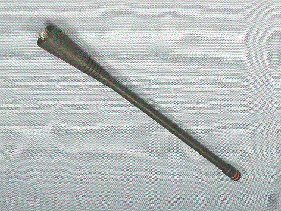
Click to zoom
Application Details
- Equipment Class
- TNF - Licensed Non-Broadcast Transmitter Held to Face
- Date of Grant
- Feb 11, 2004
- Application Purpose
- Original Equipment
- Date of Application
- Feb 11, 2004
- Equipment Note
- UHF FM PORTABLE TRANSCEIVER
- Frequency Range
- 450.00000000 - 490.00000000
- Company
- Yaesu Musen Co., Ltd.
- Country
- Japan
Documents & Files
Document Text
Text extracted from the exhibit documents filed with the FCC. Open a document above to read the original.
Users Manual
VX530 Series Operating Manual 1/6 Vertex Standard Co., Ltd. VX-530 Series Operating Manual Important Notice! FCC RF Exposure Compliance Requirements for Occupational Use Only: This Radio has been tested and complies with the Federal Communications Commission (FCC) RF exposure limits for Occupational Use/Controlled exposure environment. In addition, it complies with the following Standards and Guidelines: FCC 96-326, Guidelines for Evaluating the Environmental Effects of Radio-Frequency Radiation. FCC OET Bulletin 65 Edition 97-01 (1997) Supplement C, Evaluating Compliance with FCC Guidelines for Human Exposure to Radio Frequency Electromagnetic Fields. ANSI/IEEE C95.1-1992, IEEE Standard for Safety Levels with Respect to Human Exposure to Radio Frequency Electromagnetic Fields, 3kHz to 300 GHz. ANSI/IEEE C95.3-1992, IEEE Recommended Practice for the Measurement of Potentially Hazardous Electromagnetic Fields-RF and Microwave. This radio is NOT approved for use by the general population in an uncontrolled environment. This radio is restricted to occupational use, work related operations only where the radio operator must have the knowledge to control its RF exposure conditions. When transmitting, hold the radio in a vertical position with its microphone 1 to 2 inches (2.5 to 5 cm) away from your mouth and keep the antenna at least 1 inch (2.5cm) away from your head and body. The radio must be used with a maximum operating duty cycle not exceeding 50 %, in typical Push-to-Talk (PTT) configurations. DO NOT transmit for more than 50 % of total radio use time (50 % duty cycle). Transmitting more than 50 % of the time can cause FCC RF exposure compliance requirements to be exceeded. The radio is transmitting when the red LED on the top of the radio is illuminated. You can cause the radio to transmit by pressing the PTT button. DO NOT transmit when the radio is used in Body Worn configuration. It must be used ONLY for (1) there is a 4 cm distance from the body during transmitting, (2) monitoring purposes, using the speaker only and (3) for carrying purposes. Always use Vertex Standard authorized accessories. VX530 Series Operating Manual 2/6 Vertex Standard Co., Ltd. Controls & Connectors ▪ LED Indicator Glows Green: Scan active Blinks Green: Busy Channel (or SQL off) Glows Red: Transmit Blinks Red: Battery Voltage is low ▪ Antenna Jack ▪ PTT (Push to Talk) Switch ▪ Monitor Button ▪ Lamp Button ▪ CH (Channel) Selector ▪ VOL/PWR Knob ▪ LCD ▪ SEL1 KEY ▪ SEL2 KEY ▪ Toggle SW ▪ MIC/SP Jack (External MIC/SP) ▪ Speaker ▪ Main Microphone ▪ Sub Microphone (Noise Canceling Microphone) ▪ Battery Pack Latch Before You Begin Battery Pack Installation and Removal To install the battery, hold the transceiver with your left hand, so your palm is over the speaker and your thumb is on the top of the belt clip. Insert the battery pack into the battery compartment on the back of the radio while tilting the Belt Clip outward, then close the Battery Pack Latch until it locks in place with a “Click.” To remove the battery, turn the radio off and remove any protective cases. Open the Battery Pack latch on the bottom of the radio, then slide the battery downward and out from the radio while unfolding the Belt Clip. Caution! : Do not attempt to open any of the rechargeable Li-ion packs, as they could explode if accidentally short-circuited. Low Battery Indication As the battery discharges during use, the voltage gradually becomes lower. When the battery voltage reaches 6.0 volts, substitute a freshly charged battery and recharge the depleted pack. The TX/BUSY indicator on the top of the radio will blink red when the battery voltage is low. Avoid recharging Li-ion batteries often with little use between charges, as this can degrade the charge capacity. We recommend that you carry an extra, fully-charged pack with you so the operational battery may be used until depletion (this “deep cycling” technique promotes better long-term battery capacity). Operation Preliminary Steps Install a charged battery pack onto the transceiver, as described previously. Screw the supplied antenna onto the Antenna jack. Never attempt to operate this transceiver without an antenna connected. VX530 Series Operating Manual 3/6 Vertex Standard Co., Ltd. If you have a Speaker/Microphone, we recommend that it not be connected until you are familiar with the basic operation of the VX-530. Operation Quick Start To turn the top panel’s VOL/PWR knob clockwise to turn on the radio on. Pull and turn the top panel’s CH selector knob to choose the desired operating channel. A channel number or channel name will appear on the LCD. Rotate the VOL/PWR knob to set the volume level. If no signal is present, press and hold the Monitor button (the third button on the left side) more than 2 seconds; background noise will now be heard, and you may use this to set the VOL/PWR knob for the desired audio level. Press and hold the Monitor button more than 2 seconds (or press the Monitor button twice) to quiet the noise and resume normal (quiet) monitoring. To transmit, press and hold the PTT switch. Speak into the microphone area of the front panel grille (center right-hand corner) in a normal voice level. To return to the Receive mode, release the PTT switch. Press the top panel’s SEL1 and left side panel’s SEL2 button to active one of the preprogrammed functions that may have been enabled at the time of programming by the dealer. See the next section for details regarding the available features. Switch the top panel’s Toggle SW position to active one of the preprogrammed functions which may have been enabled at the time of programming by the dealer. There are three positions of [ A (left)], [ | (center)] and [ B (right)] in the toggle switch. See the next section for details regarding the available features. Press the DTMF keys on the telephone keypad to send DTMF tones. (If option is installed) If a Speaker/Microphone is available, remove the plas…
Text truncated - open the document above for the full version.
External Photos
FCC ID: K6610524420 IC ID: 511B-10524420 Vertex Standard Co., Ltd. Front view with antenna Front view without antenna FCC ID: K6610524420 IC ID: 511B-10524420 Vertex Standard Co., Ltd. Rear view with antenna Rear view without antenna FCC ID: K6610524420 IC ID: 511B-10524420 Vertex Standard Co., Ltd. Left view Right view FCC ID: K6610524420 IC ID: 511B-10524420 Vertex Standard Co., Ltd. Top view Bottom view FCC ID: K6610524420 IC ID: 511B-10524420 Vertex Standard Co., Ltd. Top of Battery Charger Bottom of Battery Charger FCC ID: K6610524420 IC ID: 511B-10524420 Vertex Standard Co., Ltd. Top of AC Adapter Bottom of AC Adapter FCC ID: K6610524420 IC ID: 511B-10524420 Vertex Standard Co., Ltd. Front of Microphone Back of Microphone FCC ID: K6610524420 IC ID: 511B-10524420 Vertex Standard Co., Ltd. Antenna
ID Label/Location Info
VX-537-4-5VX-537-4-5 LABEL DRAWINGLABEL DRAWING Vertex Standard Co., Ltd.Vertex Standard Co., Ltd. ID / Part 15.19 and CAUTION drawings ID drawing Part 15.19 and CAUTION drawings Label location VX-537-4-5 K6610524420 511B-10524420 4909959000000 ! ! Device restricted to occupational use to satisfy FCC RF exposure compliance. See owner's manual for specific operating requirement CAUTION This device complies with part 15 of the FCC Rules. Operation is subject to the condition that this device does not cause harmful interference.
Internal Photos
FCC ID: K6610524420 IC ID: 511B-10524420 Vertex Standard Co., Ltd. Internal view Internal view (front) FCC ID: K6610524420 IC ID: 511B-10524420 Vertex Standard Co., Ltd. Internal view (rear) Side-A of RF-UNIT with shield case FCC ID: K6610524420 IC ID: 511B-10524420 Vertex Standard Co., Ltd. Side-A of RF-UNIT without shield case Side-B of RF-UNIT FCC ID: K6610524420 IC ID: 511B-10524420 Vertex Standard Co., Ltd. CNTL-UNIT with LCD/PTT-UNIT/VR-UNIT Side-A of CNTL-UNIT FCC ID: K6610524420 IC ID: 511B-10524420 Vertex Standard Co., Ltd. Side-B of CNTL-UNIT Side-A of VR-UNIT FCC ID: K6610524420 IC ID: 511B-10524420 Vertex Standard Co., Ltd. Side-B of VR-UNIT Side-A of PTT-UNIT FCC ID: K6610524420 IC ID: 511B-10524420 Vertex Standard Co., Ltd. Side-B of PTT-UNIT Top of LCD FCC ID: K6610524420 IC ID: 511B-10524420 Vertex Standard Co., Ltd. Bottom of LCD Side-A of DUMMY-UNIT FCC ID: K6610524420 IC ID: 511B-10524420 Vertex Standard Co., Ltd. Side-B of DUMMY-UNIT Inside of chassis (front) FCC ID: K6610524420 IC ID: 511B-10524420 Vertex Standard Co., Ltd. Inside of chassis (rear)
Internal Photos
FCC ID: K6610524420 IC ID: 511B-10524420 Vertex Standard Co., Ltd. Inside top of Battery Charger Inside Bottom of Battery Charger with PWB FCC ID: K6610524420 IC ID: 511B-10524420 Vertex Standard Co., Ltd. Inside Bottom of Battery Charger without PWB Component Side of Charger PWB FCC ID: K6610524420 IC ID: 511B-10524420 Vertex Standard Co., Ltd. Solder Side of Charger PWB Inside of microphone (1) FCC ID: K6610524420 IC ID: 511B-10524420 Vertex Standard Co., Ltd. Inside of microphone (2)
Operational Description
FCC ID: K6610524420 IC ID: 511B-10524420 Circuit Description 1/3 Vertex Standard Co., Ltd. VX-537 Circuit Description 1 Overview The VX-537 is a UHF/FM hand-held transceiver designed to operate in the frequency range of 450 to 490 MHz. 2 Circuit Configuration by Frequency The receiver is a double-conversion superheterodyne with a first intermediate frequency (IF) of 44.25 MHz and a second IF of 450 kHz. Incoming signals from the antenna are mixed with the local signal from PLL to produce the first IF of 44.25 MHz. This is then mixed with the 43.8 MHz second local oscillator (using the 14.6 MHz reference crystal) output to produce the 450kHz second IF. This is detected to give the demodulated signal. The transmit signal frequency is generated by PLL VCO, and modulated by the signal from the microphone. It is then amplified and sent to the antenna. 3 Receive Signal Path 3-1 Front-end RF Amplifier Incoming RF from the antenna jack is delivered to the RF Unit and passes through a low- pass filter and high-pass filter consisting of coils L1003, L1004, L1006, L1008, L1001, L1002, L1005, L1007, L1009 & L1010, capacitors C1003, C1004, C1006, C1008, C1011, C1014, C1022, C1025, C1002, C1005, C1007, C1009, C1013,C1017,C1018, C1020, C1021, C1204, C1028 & C1031 and antenna switching diode D1004. Signals within the frequency range of the transceiver are then amplified by Q1005 and enter a varactor-tuned band-pass filter consisting of coils L1016, L1017 & L1019, capacitors C1052, C1053, C1060, C1063, C1067, C1068, C1070, C1072, C1073, C1074, C1082, C1084 & C1092 resisters R1024, R1033 and R1048, and diodes D1008, D1009, D1010, D1011, D1012 & D1013 before first mixer. 3-2 First Mixer Buffered output from the VCO is amplified by Q1012 to provide a pure first local signal between 405.75 and 445.75 MHz for injection to the first mixer Q1032. The 44.25 MHz first mixer product then passes through monolithic crystal filters XF1001 to strip away all but the desired signal. 3-3 IF Amplifier The first IF signal is amplified by Q1027. The amplified first IF signal is applied to FM IF subsystem IC Q1023 which contains the second mixer, second local oscillator, limiter amplifier, noise amplifier, and S-meter amplifier. A second local signal is generated by Q1024 using the 14.6 MHz crystal X1001 as a reference, producing a 43.8 MHz signal which yields a 450 kHz second IF when mixed with the first IF signal within Q1023. The second IF then passes through the ceramic filter CF1001 (wide channels), CF1002 (narrow channels) to strip away unwanted mixer products, and is applied to the limiter amplifier in Q1023, which removes amplitude variations in the 450 kHz IF, before detection of the speech by the ceramic discriminator CD1001. 3-4 Audio Amplifier Detected audio from Q1023 is applied to Q2023 and audio low-pass filter, and then past the volume control (Q2017) to the audio amplifier Q2004 (external speaker) or Q2009 (internal speaker), providing up to 0.5 Watts to the optional headphone jack or 16-Ω loudspeaker. Attention: Audio output is BTL output. FCC ID: K6610524420 IC ID: 511B-10524420 Circuit Description 2/3 Vertex Standard Co., Ltd. 3-5 Squelch Control The squelch circuitry consists of a noise amplifier & band-pass filter within Q1023, and noise detector D1025, D1027. When no carrier received, noise at the output of the detector stage in Q1023 is amplified and band-pass filtered by the noise amplifier section of Q1023 and the network between pins 7 and 8, and then rectified by D1025 The resulting DC squelch control voltage is passed to pin 19 of the microprocessor Q2025. If carrier is received, this signal causes pin 6 of Q2026 to go low and pin 89 of Q2025 to go high. Pin 6 of Q2026 signals Q2005, Q2013 and Q2016 to disable the supply voltage to the audio amplifier Q2004 and Q2009, while pin 89 makes Q2006 hold the green (Busy) half of the LED off, when pin 6 of Q2026 is low and pin 89 of Q2025 is high. The microprocessor then checks the DTMF decoder chip on the Optional Unit, the CTCSS and the CDCSS code for DTMF or CTCSS or CDCSS code squelch information, if enabled, respectively. If not transmitting and CTCSS or CDCSS is not activated, or if the received tone or code matches that programmed, the microprocessor stops scanning, if active, and allows audio to pass through the audio amplifier Q2004, Q2009 to the loudspeaker by enabling the supply voltage to it via Q2005 and Q2011 . 4 Transmit Signal Path 4-1 Microphone Amplifier Speech input from the microphone is amplified in Q2030 after there is a filter and is sent to Q2017 and sent to Dummy Unit (or Optional Unit). The audio, which returned from Dummy Unit, passes Q2023 to be pre-emphasized. The processed audio is then mixed with a CTCSS tone generated by Q2023 and delivered to D1015 for frequency modulating the PLL carrier up to ±5 kHz from the unmodulated carrier at the transmitting frequency. If a CDCSS code is enabled for transmission, the code is generated by the microprocessor Q2025 and delivered to X1001 (TCXO 14.6 MHz) for CDCSS modulating. If DTMF is enabled for transmission, the tone is generated by the microprocessor Q2025 and applied to the splutter filter (Q2023) in place of speech audio. Also, the tone is amplified for monitoring in the loudspeaker. 4-2 Noise Canceling Microphone Circuit The two signals from internal microphone (main and sub) are input to the positive input (sub) and to the negative input (main) and of the Q2030. If the same signal is input to both main and sub, the main signal is canceled at the output of Pin1 of the Q2030. In other words, noise from nearby sources not directly connected to the transceiver enters the main and sub input at the same signal and is therefore canceled out. When a signal is only input to main and there is no signal at sub, the main signal is output as is from Q2030. 4-3 Drive and Final Amplifier The modulated signal from the VCO Q1022 is buffered by Q1032 and amplified by Q1017 and Q1013. The low-l…
Text truncated - open the document above for the full version.
Parts List/Tune Up Info
FCC ID: K6610524420 IC ID: 511B-10524420 Alignment 1/6 Vertex Standard Co., Ltd. VX-537 Alignment Introduction The VX-530 is carefully aligned at the factory for the specified performance across the frequency range specified for each version. Realignment should therefore not be necessary except in the event of a component failure, or altering version type. All component replacement and service should be performed only by an authorized Vertex Standard representative, or the warranty policy may be void. The following procedures cover the sometimes critical and tedious adjustments that are not normally required once the transceiver has left the factory. However, if damage occurs and some parts subsequently are placed, realignment may be required. If a sudden problem occurs during normal operation, it is likely due to component failure; realignment should not be done until after the faulty component has been replaced. We recommend that servicing be performed only by authorized Vertex Standard service technicians who are experienced with the circuitry and fully equipped for repair and alignment. Therefore, if a fault is suspected, contact the dealer from whom the transceiver was purchased for instructions regarding repair. Authorized Vertex Standard service technicians realign all circuits and make complete performance checks to ensure compliance with factory specifications after replacing any faulty components. Those who do undertake any of the following alignments are cautioned to proceed at their own risk. Problems caused by unauthorized attempts at realignment are not covered by the warranty policy. Also, Vertex Standard reserves the right to change circuits and alignment procedures in the interest of improved performance, without notifying owners. Under no circumstances should any alignment be attempted unless the normal function and operation of the transceiver are clearly understood, the cause of the malfunction has been clearly pinpointed and any faulty components replaced, and realignment determined to be absolutely necessary. The following test equipment (and thorough familiarity with its correct use) is necessary for complete realignment. Correction of problems caused by misalignment resulting from use of improper test equipment is not covered under the warranty policy. While most steps do not require all of the equipment listed, the interactions of some adjustments may require that more complex adjustments be performed afterwards. Do not attempt to perform only a single step unless it is clearly isolated electrically from all other steps. Have all test equipment ready before beginning, and follow all of the steps in a section in the order presented. FCC ID: K6610524420 IC ID: 511B-10524420 Alignment 2/6 Vertex Standard Co., Ltd. Required Test Equipment ・ RF Signal Generator with calibrated output level at 600 MHz ・ Deviation Meter (linear detector) ・ In-line Wattmeter with 5 % accuracy at 600 MHz ・ 50 Ω RF Dummy Load with power rating 10 W at 600 MHz ・ 16 Ω AF Dummy Load (Attention: Audio output is BTL output) ・ Regulated DC Power Supply (standard 7.5 V DC, 3 A) ・ Frequency Counter with 0.2 ppm accuracy at 600 MHz ・ AC Voltmeter ・ DC Voltmeter ・ UHF Sampling Coupler ・ IBM PC / compatible Computer with Microsoft DOS v3.0 or later operating system ・ Vertex Standard CT-71 Connection Cable & Alignment program Alignment Preparation & Precautions A 50 Ω RF Dummy Load and in-line wattmeter must be connected to the main antenna jack in all procedures that call for transmission, except where specified otherwise. Correct alignment is not possible with an antenna. After completing one step, read the following step to determine whether the same test equipment will be required. If not, remove the test equipment (except dummy load and wattmeter, in connected) before proceeding. Correct alignment requires that the ambient temperature be the same as that of the transceiver and test equipment, and that this temperature be held constant between 20 and 30 °C (68 to 86 °F). When the transceiver is brought into the shop from hot or cold air, it should be allowed time to come to room temperature before alignment. Whenever possible, alignments should be made with oscillator shields and circuit boards firmly affixed in place. Also, the test equipment must be thoroughly warmed up before beginning. Note: Signal levels in dB referred to in the alignment procedure are based on 0dBμ EMF = 1μV. Setup the test equipment as shown for transceiver alignment, apply 7.5V DC power to the transceiver. Refer to the drawings above for Alignment Points. PC POWER SUPPLY 7.5V DC RF SIGNAL GENERATOR 50 Ω DUMMY LOAD IN-LINE WATTMETER DEVIATION METER FREQUENCY COUNTER RF SAMPLING COUPLER TRANSCEIVER ANT MIC/EAR COM port CT-71 connection cable FCC ID: K6610524420 IC ID: 511B-10524420 Alignment 3/6 Vertex Standard Co., Ltd. The transceiver must be programmed for use in the intended system before alignment is attempted. The RF parameters are loaded from the file during the alignment process. In order to facilitate alignment over the complete switching range of the equipment it is recommended that the channel data in the transceiver is preset as the chart below. ChannelsFrequency (Simplex) Band-LOW450.000 MHz Band-MID470.000 MHz Band-HIGH490.000 MHz The alignment mode is accessed by “Alignment mode” command from the computer whilst switching on. And the alignment tool operates it automatically. During the alignment mode, normal operation is suspended. Use the alignment tool program running on PC. The alignment tool outline Installation the tool This alignment tool consists, MS-DOS based, only one execute file " vx-530adj.exe ". You make a directly as you think fit, and copy this file. That is all of the installation process. Boot the tool Change directly and input in command line, " vx-530adj [enter] ", and boot the alignment tool. Enter to the alignment mode To enter the alignment mode, turn off the power of the transceiver, and…
Text truncated - open the document above for the full version.
Parts List/Tune Up Info
1/2 FCC ID: K6610524420 IC ID: 511B-10524420 Component Applications Address Device nameDescriptionApplication [RF-UNIT] D1001 Diode HVU131 ANT SW D1002 Zener Diode PTZ 15A Protector D1003 Diode MA2S111 TX/RX SW D1004 Diode HVU131 ANT SW D1005 Dual Diode RB715F Power DET D1006 Diode MA2S111 Protector D1007 Zener Diode UDZS 3.9B Protector D1008 Varactor Diode HVC350B RX TUNE D1009 Varactor Diode HVC350B RX TUNE D1010 Varactor Diode HVC350B RX TUNE D1011 Varactor Diode HVC350B RX TUNE D1012 Varactor Diode HVC350B RX TUNE D1013 Varactor Diode HVC350B RX TUNE D1014 Dual Diode MA132WK TX/RX SW D1015 Varactor Diode HVC350B MOD D1017 Diode MA2S111 Prorector D1018 Varactor Diode HVC350B TX VCO Freq Cont D1019 Varactor Diode HVC350B TX VCO Freq Cont D1020 Varactor Diode HVC350B RX VCO Freq Cont D1021 Varactor Diode HVC350B RX VCO Freq Cont D1022 Varactor Diode HVC350B RX VCO Freq Cont D1023 Varactor Diode HVC350B RX VCO Freq Cont D1024 Dual Diode MA132WK WIDE/NARROW SW D1025 Dual Diode DA221 NOISE DET D1026 Dual Diode MA132WK WIDE/NARROW SW D1027 Dual Diode DA221 WIDE/NARROW SW D1028 Diode MA2S111 Protector D1029 Dual Diode DA221 LIMITTER Q1001 Dual Transister XP1501 TX5V AVR Q1002 Transister CPH6102 TX5V AVR Q1003 Dual Transister UMG2N TX/RX SW Q1004 IC NJM2871AF05 5V AVR Q1005 IC BIC702M RF AMP Q1006 Transister UN911F RX 5V SW Q1007 Hybird RF Module RA07M4452M PA Q1008 Transister UN911F SAVE SW Q1009 Transister DTC144EE TRX SW Q1010 Transister DTC114TE TRX SW Q1011 Transister DTC144EE PO OFF SW Q1012 Transister 2SC5226-4 Buff AMP Q1013 Transister 2SC3356-R25 Pre DRIVE Q1014 Transister DTC114TE Buff AMP SW Q1015 Transister DTC144EE Buff AMP SW Q1016 Transister 2SC5226-4 Buff AMP Q1017 Transister 2SC5226-4 Buff Q1018 Dual OP-AMP NJM12904R APC/RX TUNE Q1019 Transister DTC144EE RX VCO SW Q1020 Transister DTC114TE TX VCO SW Q1021 FET 2SK508-K52 RX VCO Q1022 Transister 2SC4227-R34 TX VCO Q1023 IC TA31136FN FM Sub-System IC Q1024 Transister 2SC4617 R 2nd LOCAL OSC Q1025 IC SA7025DK PLL IC Q1026 Transister 2SC4617 R FILTER AMP Q1027 Transister 2SC5226-4 IF AMP Q1028 Transister 2SC4617 R Ripple Filter Q1029 OP-AMP TA75S01F FREQ ADJ Q1030 Transister DTC144EE WIDE/NARROW SW Q1031 Transister DTC144EE WIDE/NARROW SW Q1032 FET SPM5001 MIXER [CNTL-UNIT] D2001 Dual Diode DA221 Protector D2002 Dual Diode DA221 Protector D2003 Diode 1SS400G Protector D2004 Diode 1SS400G Protector D2005 Diode 1SS400G Protector D2006 Diode 1SS400G Protector D2007 Diode 1SS400G Protector VX-537-4-5 Vertex Standard Co., Ltd. 2/2 FCC ID: K6610524420 IC ID: 511B-10524420 Component Applications Address Device nameDescriptionApplication VX-537-4-5 D2008 Diode 1SS400G Protector D2009 Diode 1SS400G Protector D2010 Dual Diode DA221 Protector D2011 Dual Diode DA221 Protector D2012 Dual Diode DA221 Protector D2020 Diode 1SS400G Protector D2021 Dual Diode DA221 RESET D2022 Zener Diode HZU4ALL Protector D2023 Dual Diode DA221 LIMITTER D2024 Diode 1SS400G Protector D2026 Dual Diode DA221 LIMMITTER D2027 Dual Diode DA221 TEMP DET D2029 Diode 1SS400G Protector D2030 Diode 1SS400G Protector D2031 Diode 1SS400G Protector D2032 Diode 1SS400G Protector D2034 Dual LED CL-165HR/YG-D-T TX/RX LED Q2003 Transister 2SA1767 Q LAMP DRIVER Q2004 IC TDA2822D EXT AF AMP Q2005 Transister CPH6102 AF AMP SW Q2006 Dual Transister UMG2N TRX LED SW Q2007 Transister DTC114TE LAMP SW Q2009 IC TDA2822D INT AF AMP Q2010 Dual Transister XN1501 3.5V AVR Q2011 Transister 2SA1774 R CURRENT SENS Q2012 Transister CPH6102 3.5V AVR Q2013 Dual Transister UMC5N AF AMP SEL Q2014 IC S-80735SN-DZ RESET Q2015 Transister DTC144EE AF AMP SEL Q2016 Dual Transister UMC5N AF AMP SEL Q2017 IC M62364FP_600D D/A Converter Q2018 Transister DTC144EE 3.5V REG SW Q2019 IC NJM2871AF35 3.5V AVR Q2020 Transister 2SC4617 R RESET Q2021 Transister 2SC4617 R Clock Shift Q2022 Transister DTC144EE NARROW ATT SW Q2023 IC AK2345 AUDIO PROSSESOR Q2024 IC S-93C56AMFN EEPROM Q2025 IC LC87F74C8A-TQFP Main Microprocessor Q2026 IC BU2090FS-E1 BEEP CNTL/PORT CNTL Q2027 Transister UN911F WIDE/NARROW SW Q2028 Transister UN911F LAMP SW Q2029 Dual OP-AMP NJM12904R AF AMP Q2030 Quadruple OP-AMP NJM2902V MIC AMP/AF FILTER Q2031 Quadruple OP-AMP NJM2902V CTCSS DEC2 Q2032 Transister 2SA1602A-1F AUDIO MUTE Q2033 Transister DTC114TE AUDIO MUTE Q2034 Transister DTA114EEMIC SELECT SW Q2035 Transister DTA124EENC MIC SW Q2036 IC TC4W53FUMIC SELECT SW [VR-UNIT] D5001 LED CL-190TD-CD LCD LAMP D5002 LED CL-190TD-CD LCD LAMP [INTERFACE-UNIT] D6001 Dual DiodeDAP222 Mic Mute Cntl Q6001 Transister DTC144EE MDS-1200 ANI SW Q6002 Transister DTC144EE MDS-1200 PTT SW [KEY-UNIT] D6001 Diode 1SS400G Protector D6002 Diode LNJ808K8SRA KEY LAMP D6003 Diode LNJ808K8SRA KEY LAMP D6004 Diode LNJ808K8SRA KEY LAMP D6005 Diode LNJ808K8SRA KEY LAMP Q6001 Transister PDTC114TE LAMP SW Vertex Standard Co., Ltd.
RF Exposure Info
© 2004 Celltech Labs Inc. 1 of 20 Test Report S/N: 122203-458K66 Test Date(s): January 12, 2004 Test Type: FCC/IC SAR Evaluation Celltech Labs Inc. declares under its sole responsibility that this wireless portable device has demonstrated compliance with the Specific Absorption Rate (SAR) RF exposure requirements specified in FCC 47 CFR §2.1093 and Health Canada’s Safety Code 6. The device was tested in accordance with the measurement standards and procedures specified in FCC OET Bulletin 65, Supplement C (Edition 01-01) and Industry Canada RSS-102 Issue 1 (Provisional) for the Occupational / Controlled Exposure environment. All measurements were performed in accordance with the SAR system manufacturer recommendations. I attest to the accuracy of data. All measurements were performed by me or were made under my supervision and are correct to the best of my knowledge and belief. I assume full responsibility for the completeness of these measurements and vouch for the qualifications of all persons taking them. This test report shall not be reproduced partially, or in full, without the prior written approval of Celltech Labs Inc. The results and statements contained in this report pertain only to the device(s) evaluated. Russell W. Pipe Senior Compliance Technologist Celltech Labs Inc. DECLARATION OF COMPLIANCE SAR RF EXPOSURE EVALUATION Test Lab CELLTECH LABS INC. Testing and Engineering Services 1955 Moss Court Kelowna, B.C. Canada V1Y 9L3 Phone: 250-448-7047 Fax: 250-448-7046 e-mail: [email protected] web site: www.celltechlabs.com Applicant Information VERTEX STANDARD CO., LTD. 4-8-8, Nakameguro, Meguro-Ku Tokyo 153-8644 Japan Rule Part(s): FCC 47 CFR §2.1093; IC RSS-102 Issue 1 (Provisional) Test Procedure(s): FCC OET Bulletin 65, Supplement C (01-01) Device Classification: Licensed Non-Broadcast Transmitter Held to Face (TNF) Device Type: Portable UHF PTT Radio Transceiver FCC ID: K6610524420 Model(s): VX-537-4-5 Modulation: FM (UHF) TX Frequency Range: 450.00 - 490.00 MHz Max. RF Output Power Tested: 36.88 dBm Conducted (450 MHz) 36.90 dBm Conducted (470 MHz) 36.72 dBm Conducted (490 MHz) Antenna Type(s): Whip 450-470 MHz (P/N: ATU-5D) Whip 470-512 MHz (P/N: ATU-5F) Battery Type(s): NiCd 7.2 V, 1700 mAh (P/N: FNB-29AIS) Body-Worn Accessories: Belt-Clip, Speaker-Microphone (MH-50) Max. SAR Measured: Face-held: 2.58 W/kg (50% Duty Cycle) Body-worn: 7.10 W/kg (50% Duty Cycle) © 2004 Celltech Labs Inc. 2 of 20 Test Report S/N: 122203-458K66 Test Date(s): January 12, 2004 Test Type: FCC/IC SAR Evaluation TABLE OF CONTENTS 1.0INTRODUCTION.....................................................................3 2.0DESCRIPTION OF DUT............................................................ 3 3.0SAR MEASUREMENT SYSTEM................................................ 4 4.0MEASUREMENT SUMMARY..................................................... 5 5.0DETAILS OF SAR EVALUATION............................................... 6 6.0EVALUATION PROCEDURES................................................... 6 7.0SYSTEM PERFORMANCE CHECK............................................. 7 8.0SIMULATED EQUIVALENT TISSUES.......................................... 8 9.0SAR SAFETY LIMITS............................................................... 8 10.0ROBOT SYSTEM SPECIFICATIONS........................................... 9 11.0PROBE SPECIFICATION.......................................................... 10 12.0PLANAR PHANTOM................................................................. 10 13.0VALIDATION PHANTOM........................................................... 10 14.0DEVICE HOLDER.................................................................... 10 15.0TEST EQUIPMENT LIST............................................................ 11 16.0MEASUREMENT UNCERTAINTIES............................................. 12-13 17.0REFERENCES.........................................................................14 APPENDIX A - SAR MEASUREMENT DATA............................................... 15 APPENDIX B - SYSTEM PERFORMANCE CHECK DATA............................ 16 APPENDIX C - SYSTEM VALIDATION PROCEDURES................................. 17 APPENDIX D - PROBE CALIBRATION............…
Text truncated - open the document above for the full version.
Contact Information
Applicant
Masatoshi Muraishi(Engineering Division)
Test Firm
M. Flom Associates, Inc.Morton Flom
Technical Specifications
| # | Rule Parts | Frequency Range | Power Output | Emission | Tolerance |
|---|---|---|---|---|---|
| 4 | 9 | 450 MHz - 490 MHz | 5 W | 11K0F3E | 2.5 ppm |
Other Applications from Yaesu Musen Co., Ltd.
K660E180X10
Dec 01, 2025BLUETOOTH MICROPHONE
Equipment Class
DTS - Digital Transmission System
K6630673Y3D
Aug 01, 2024VHF FM Marine Transceiver
Equipment Class
CXX - Communications Rcvr for use w/ licensed Tx and CBs
K6630653Y3D
Aug 01, 2024VHF FM Marine Transceiver
Equipment Class
CXX - Communications Rcvr for use w/ licensed Tx and CBs
K6630683X30
Jan 10, 2023VHF FM Marine Transceiver
Equipment Class
TNF - Licensed Non-Broadcast Transmitter Held to Face
K6650033X30
Nov 18, 2020Airband Radio Transceiver
Equipment Class
TNF - Licensed Non-Broadcast Transmitter Held to Face