K6620175X20scanning receiver
Yaesu Musen Co., Ltd.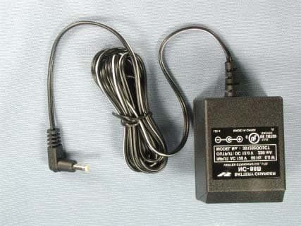
Click to zoom
Application Details
- Equipment Class
- CSR - Scanning Receiver
- Date of Grant
- May 20, 2004
- Application Purpose
- Original Equipment
- Date of Application
- May 20, 2004
- Equipment Note
- scanning receiver
- Frequency Range
- 895.01000000 - 960.00000000
- Company
- Yaesu Musen Co., Ltd.
- Country
- Japan
Documents & Files
Document Text
Text extracted from the exhibit documents filed with the FCC. Open a document above to read the original.
Users Manual
FCC ID: K6620175X20 IC ID: 511B-20175X20 Operating Manual 1/44 Vertex Standard Co., Ltd. FT-60R Operating Manual General Description The FT-60R is a dual band FM transceiver with extensive receive frequency coverage, providing local-area two-way amateur communications along with unmatched monitoring capability. The FT-60R’s small size allows you to take it anywhere - hiking, skiing, or while walking around town - and its operating flexibility brings the user many avenues of operating enjoyment. Its incredibly tiny FNB-83 Rechargeable Nickel-Metal Hydride Battery Pack provides up to 5 Watts of transmit power on 144 MHz and 430 MHz Amateur Bands. Besides 144- and 430-MHz transceive operation, the FT-60R provides receive coverage of the VHF and UHF TV bands, the VHF AM aircraft band, and a wide range of commercial and public safety frequencies! New and exciting features of the FT-60R are the Emergency Automatic ID (EAI) function, that will automatically cause your FT-60R to transmit your callsign and engage your rig’s microphone, even if you are disabled and unable to press the PTT switch; Enhanced Paging and Code Squelch (EPCS), that allows you to page a particular station and only receive calls from that station, if desired; and a security Password feature, that will allow you to turn on and operate your transceiver only after you enter your Password. Additional features include a convenient access key for Vertex Standard’s WIRES ™ (Wide- coverage Internet Repeater Enhancement System), a transmit Time-Out Timer (TOT), Automatic Power-Off (APO), Automatic Repeater Shift (ARS), Yaesu’s exclusive ARTS ™ (Auto-Range Transponder System) which “beeps” the user when you move out of communications range with another ARTS TM equipped station, plus provision for reduction of the TX deviation in areas of high channel congestion. And an RF squelch circuit allows the owner to set the squelch to open at a programmable setting of the S-Meter, thus reducing guesswork in setting the squelch threshold. We appreciate your purchase of the FT-60R, and encourage you to read this manual thoroughly, so as to learn about the many exciting features of your exciting new Yaesu hand-held transceiver! FCC ID: K6620175X20 IC ID: 511B-20175X20 Operating Manual 2/44 Vertex Standard Co., Ltd. Accessories & Options Supplied Accessories FNB-837.2 V, 1,400 mAh Rechargeable Nickel-Metal Hydride Battery Pack NC-88A/B, C, U*Overnight Battery Charger Belt Clip Antenna Operating Manual Warranty Card Available Options FNB-837.2 V, 1,400 mAh Rechargeable Nickel-Metal Hydride Battery Pack CD-29A/B, C, U*1.5-Hour Charger CN-3BNC-to-SMA Adapter CSC-77Soft Case CT-27Cloning Cable CT-44Microphone Adapter E-DC-5BDC Cable with Cigarette-Lighter Adapter MH-34B4BSpeaker/Microphone MH-37A4BEar piece/Microphone VC-25VOX Headset * “A/B” suffix is for use with 100-120 VAC, “C” suffix is for use with 230-240 VAC, and “U” suffix is for use with 230 VAC. Availability of accessories may vary. Some accessories are supplied as standard per local requirements, while others may be unavailable in some regions. Consult your Yaesu dealer for details regarding these and any newly-available options. Connection of any non-Yaesu- approved accessory, should it cause damage, may void the Limited Warranty on this apparatus. Control & Connections ANTENNA Jack Connect the supplied rubber flex antenna (or another antenna presenting a 50-Ohm impedance) here. VOL/PWR Knob Turn this control clockwise to turn the radio on and to increase the volume. Counter- clockwise rotation into the click-stop will turn the radio off. TX/BUSY Indicator Lamp This indicator glows green when the squelch opens, and turns red during transmit. DIAL Knob This (inner) 20-position detented rotary switch is used for setting the operating frequency, and also is used for menu selections and other adjustments. SQL Knob This (outer) control is used to silence background noise on the receiver. It should be advanced clockwise just to the point where the noise is silenced (and the green “BUSY” indicator turns off). FCC ID: K6620175X20 IC ID: 511B-20175X20 Operating Manual 3/44 Vertex Standard Co., Ltd. PTT (Push To Talk) Switch Press this switch to transmit, and release it (to receive) after your transmission is completed. MONI Switch Pressing this switch disables the noise squelching action, allowing you to hear very weak signals near the background noise level temporarily. Press the [F/W] key on the keypad first, then press this switch to “open” the squelch continuously. Press this switch again to resume normal (quiet) monitoring. LAMP Switch Pressing this switch illuminates the LCD and keypad for five seconds, after which the back- lighting will automatically turn off. Press the [F/W] key on the keypad first, then press this switch to activate the back-lighting lamp continuously. To turn the lamp off, press this switch again. You can change the primary (press key) function of this switch, if you prefer. See page ?? for details. KEYPAD These 16 keys select many of most important operating features on the FT-60R. The functions of the keys are described in detail on the pages to follow. SPEAKER The internal speaker is located here. MIC The internal microphone is located here. MIC/SP Jack This four-conductor miniature jack provides connection points for microphone audio, earphone audio, PTT, and ground. EXT DC Jack This coaxial DC jack allows connection to an external DC power source (6-16V DC). The center pin of this jack is the Positive (+) connection. Keypad Functions KeyPress KeyPress [F/W] Key +Press and Hold Key [1(SQ TYP)]Frequency entry digit “1” Activates the CTCSS or DCS Operation Recalls the “Weather” broadcast channel bank [2(CODE)]Frequency entry digit “2” Selects the CTCSS tone or DCS code number Activates the ARTS feature [3(TX PO)]Frequency entry digit “3” Selects the desired transmit power output level Activates the Smart Search feature [UP(MHz)]Increa…
Text truncated - open the document above for the full version.
External Photos
FCC ID: K6620175X20 IC ID: 511B-20175X20 Vertex Standard Co., Ltd. Front view with antenna Rear view with antenna FCC ID: K6620175X20 IC ID: 511B-20175X20 Vertex Standard Co., Ltd. Rear view without antenna Rear view without antenna FCC ID: K6620175X20 IC ID: 511B-20175X20 Vertex Standard Co., Ltd. Top view Bottom view FCC ID: K6620175X20 IC ID: 511B-20175X20 Vertex Standard Co., Ltd. Left side view Right side view FCC ID: K6620175X20 IC ID: 511B-20175X20 Vertex Standard Co., Ltd. Battery pack Battery pack FCC ID: K6620175X20 IC ID: 511B-20175X20 Vertex Standard Co., Ltd. Microphone Microphone FCC ID: K6620175X20 IC ID: 511B-20175X20 Vertex Standard Co., Ltd. Battery charger Battery charger FCC ID: K6620175X20 IC ID: 511B-20175X20 Vertex Standard Co., Ltd. Antenna
ID Label/Location Info
FT-60RFT-60R LABEL DRAWINGLABEL DRAWING Vertex Standard Co., Ltd.Vertex Standard Co., Ltd. ID / Part 15.19 and CAUTION drawings ID drawing Part 15.19 and CAUTION drawings Label location WARNING: MODIFICATION OF THIS DEVICE FCC RULES AND FEDERAL LAW. TO RECEIVE CELLULAR RADIOTELEPHONE SERVICE SIGNALS IS PROHIBITED UNDER This device complies with part 15 of the FCC Rules. Operation is subject to the following two conditions: (1) This device may not cause harmful interference, and (2) this device must accept any interference received, Including interference that may cause undesired operation. FT-60R K6620175X20 511B-20175X20 4909959000000
Test Report
TIMCO ENGINEERING INC. 849 NW State Road 45 Newberry, Florida 32669 http://www.timcoengr.com 888.472.2424 F 352.472.2030 email: [email protected] APPLICANT: VERTEX STANDARD CO., LTD. Test Report Product Name: SCANNING RECEIVER FCC ID: K6620175X20 Applicant: VERTEX STANDARD CO., LTD. 4 – 8 –8 NAKAMEGURO, MEGURO-KU TOKYO, 153-8644 JAPAN Date Receipt: MAY 5, 2004 Date Tested: MAY 13, 2004 FCC ID: K6620475X20 REPORT #: V\VERTEX\641AUT4\641AUT4TestRepord.doc COVER SHEET TIMCO ENGINEERING INC. 849 NW State Road 45 Newberry, Florida 32669 http://www.timcoengr.com 888.472.2424 F 352.472.2030 email: [email protected] APPLICANT: VERTEX STANDARD CO., LTD. TABLE OF CONTENTS LIST APPLICANT: VERTEX STANDARD CO., LTD. FCC ID: K6620175X20 TEST REPORT CONTAINING: PAGE 1............EQUIPMENT LIST PAGE 2............TEST PROCEDURE PAGE 3............RADIATION INTERFERENCE TEST DATA PAGE 4-6..........POWER LINE CONDUCTED EMISSIONS TEST DATA PAGE 7............38 dB Rejection Ratio EXHIBITS CONTAINING: CONFIDENTIALITY REQUEST LETTER BLOCK DIAGRAM SCHEMATIC USERS MANUAL LABEL SAMPLE LABEL LOCATION EXTERNAL PHOTOGRAPHS INTERNAL PHOTOGRAPHS CIRCUIT DESCRIPTION TEST SET UP PHOTOGRAPHS FCC ID: K6620475X20 REPORT #: V\VERTEX\641AUT4\641AUT4TestRepord.doc TABLE OF CONTENTS TIMCO ENGINEERING INC. 849 NW State Road 45 Newberry, Florida 32669 http://www.timcoengr.com 888.472.2424 F 352.472.2030 email: [email protected] APPLICANT: VERTEX STANDARD CO., LTD. EMC Equipment List Device Manufacturer Model Serial Number Cal/Char Date Due Date 3/10-Meter OATS TEI N/A N/A Listed 3/27/04 3/26/07 Biconnical Antenna Eaton 94455-1 1057 CAL 3/18/03 3/18/05 Biconnical Antenna Eaton 94455-1 1096 CAL 10/1/01 10/1/03 Biconnical Antenna Electro- Metrics BIA-25 1171 CAL 4/26/01 4/26/03 Blue Tower Quasi-Peak Adapter HP 85650A 2811A01279 CAL 4/15/03 4/15/05 Blue Tower RF Preselector HP 85685A 2620A00294 out for Cal Blue Tower Spectrum Analyzer HP 8568B 2928A04729 2848A18049 CAL 4/15/03 4/15/05 Signal Generator HP 8640B 2308A21464 CAL 2/15/02 2/15/04 Silver Tower Preamplifier HP 8449B 3008A01075 CAL 3/22/04 3/22/06 Silver Tower Quasi-Peak Adapter HP 85650A 3303A01844 CAL 3/22/04 3/22/06 Silver Tower RF Preselector HP 85685A 2926A00983 CAL 3/22/04 3/22/06 Silver Tower Spectrum Analyzer HP 8566B Opt 462 3552A22064 3638A08608 CAL 3/22/04 3/22/06 Tan Tower Preamplifier HP 8449B-H02 3008A00372 CAL 9/23/03 9/23/05 Tan Tower Quasi-Peak Adapter HP 85650A 3303A01690 CAL 9/23/03 9/23/05 Tan Tower RF Preselector HP 85685A 3221A01400 CAL 9/23/03 9/23/05 Tan Tower Spectrum Analyzer HP 8566B Opt 462 3138A07786 3144A20661 CAL 9/23/03 9/23/05 FCC ID: K6620475X20 REPORT #: V\VERTEX\641AUT4\641AUT4TestRepord.doc Page 1 of 7 TIMCO ENGINEERING INC. 849 NW State Road 45 Newberry, Florida 32669 http://www.timcoengr.com 888.472.2424 F 352.472.2030 email: [email protected] APPLICANT: VERTEX STANDARD CO., LTD. TEST PROCEDURE GENERAL: This report shall NOT be reproduced except in full without the written approval of TIMCO ENGINEERING, INC. RADIATION INTERFERENCE: The test procedure used was ANSI STANDARD C63.4-1992 using a HEWLETT PACKARD spectrum analyzer with a preselector. The bandwidth of the spectrum analyzer was 100 kHz with an appropriate sweep speed. The analyzer was calibrated in dB above a microvolt at the output of the antenna. The resolution bandwidth was 100KHz and the video bandwidth was 300KHz. The ambient temperature of the UUT was 80ºC with a humidity of 76%. FORMULA OF CONVERSION FACTORS: The Field Strength at 3m was established by adding the meter reading of the spectrum analyzer (which is set to read in units of dBuV) to the antenna correction factor supplied by the antenna manufacturer. The antenna correction factors are stated in terms of dB. The gain of the Preselector was accounted for in the Spectrum Analyzer Meter Reading. Example: Freq (MHz) METER READING + ACF = FS 33 20 dBuV + 10.36 dB = 30.36 dBuV/m @ 3m ANSI STANDARD C63.4-1992 10.1.7 MEASUREMENT PROCEDURES: The unit under test was placed on a table 80 cm high and with dimensions of 1m by 1.5m. The table used for radiated measurements is capable of continuous rotation. When an emission was found, the table was rotated to produce the maximum signal strength. At this point, the antenna was raised and lowered from 1m to 4m. The antenna was placed in both the horizontal and vertical planes. The situation was similar for the conducted measurement except that the table did not rotate. The EUT was setup as described in ANSIC63.4-1992 with the EUT 40 cm from the vertical ground wall. FCC ID: K6620475X20 REPORT #: V\VERTEX\641AUT4\641AUT4TestRepord.doc Page 2 of 7 TIMCO ENGINEERING INC. 849 NW State Road 45 Newberry, Florida 32669 http://www.timcoengr.com 888.472.2424 F 352.472.2030 email: [email protected] APPLICANT: VERTEX STANDARD CO., LTD. APPLICANT: VERTEX STANDARD CO., LTD. FCC ID: K6620175X20 NAME OF TEST: RADIATION INTERFERENCE RULES PART NUMBER: 15.109 REQUIREMENTS: 30 to 80 MHz: 40.0 dBuV/M @ 3 METERS 88 to 216 MHz: 43.5 dBuV/M 216 to 960 MHz: 46.0 dBuV/M ABOVE 960 MHz: 54.0 dBuV/M TEST RESULTS: A search was made of the spectrum from 30 to 1000 MHz and the measurements indicate that the unit DOES meet the FCC requirements. TEST DATA: Tuned Frequency MHz Emission Frequency MHz Meter Reading dBuV Ant. Polarity Coax Loss dB Correction Factor dB Field Strength dBuV/m Margin dB 108.0 156.30 4.3 V 1.79 17.93 24.02 19.48 150.0 197.35 5.3 V 2.08 17.31 24.69 18.81 200.0 247.25 7.2 V 2.34 12.34 21.88 21.62 203.0 250.05 6.6 V 2.35 12.50 21.45 22.05 250.0 297.25 2.4 V 2.59 13.66 18.65 27.35 300.0 347.05 2.9 V 2.84 14.67 20.41 25.59 300.0 347.25 8.0 V 2.84 14.67 25.51 20.49 350.0 397.35 9.9 V 3.09 15.90 28.89 17.11 400.0 447.35 8.0 V 3.29 18.00 29.29 16.71 400.0 451.98 11.1 V 3.31 18.20 32.61 13.39 450.0 497.25 3.4 V 3.49 17.90 24.79 21.21 520.0 567.35 7.0 V 3.70 18.75 29.45 16.55 700.0 747.25 3.7 V 4.59 21.00 29.29 16.71 850.0 897.25 2.2 V 4.90 22.82 29.92 16.08 1,000.0 1,047.25 4.1 V 1.22 25.36 30.…
Text truncated - open the document above for the full version.
Contact Information
Applicant
Masatoshi Muraishi(Engineering Division)
Test Firm
Timco Engineering, Inc.Sid Sanders
Technical Specifications
| # | Rule Parts | Frequency Range | Power Output |
|---|---|---|---|
| 4 | 15B | 895.01 MHz - 960 MHz | - |
Other Applications from Yaesu Musen Co., Ltd.
K660E180X10
Dec 01, 2025BLUETOOTH MICROPHONE
Equipment Class
DTS - Digital Transmission System
K6630673Y3D
Aug 01, 2024VHF FM Marine Transceiver
Equipment Class
CXX - Communications Rcvr for use w/ licensed Tx and CBs
K6630653Y3D
Aug 01, 2024VHF FM Marine Transceiver
Equipment Class
CXX - Communications Rcvr for use w/ licensed Tx and CBs
K6630683X30
Jan 10, 2023VHF FM Marine Transceiver
Equipment Class
TNF - Licensed Non-Broadcast Transmitter Held to Face
K6650033X30
Nov 18, 2020Airband Radio Transceiver
Equipment Class
TNF - Licensed Non-Broadcast Transmitter Held to Face