K6620223X20SCANNING RECEIVER
Yaesu Musen Co., Ltd.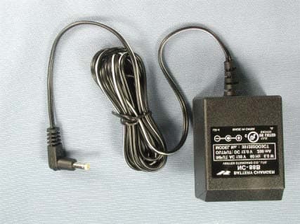
Click to zoom
Application Details
- Equipment Class
- CSR - Scanning Receiver
- Date of Grant
- Apr 07, 2005
- Application Purpose
- Original Equipment
- Date of Application
- Apr 07, 2005
- Equipment Note
- SCANNING RECEIVER
- Frequency Range
- 137.00000000 - 174.00000000
- Company
- Yaesu Musen Co., Ltd.
- Country
- Japan
Documents & Files
Document Text
Text extracted from the exhibit documents filed with the FCC. Open a document above to read the original.
Users Manual
FCC ID: K6620223X20 IC ID: 511B-20223X20 VX-120/170 O PERATING MANUAL 1/64 Vertex Standard Co., Ltd. General Description The VX-120/170 is a small size FM hand-held providing up to five watts of RF power and wealth of convenient features for 2m amateur band. New and exciting features of the VX-120/170 are the Emergency Automatic ID (EAI) function, that will automatically cause your VX-120/170 to transmit your callsign and engage your rig’s microphone, even if you are disabled and unable to press the PTT switch; Enhanced Paging and Code Squelch (EPCS), that allows you to page a particular station and only receive calls from that station, if desired; and a security Password feature, that will allow you to turn on and operate your transceiver only after you enter your Password. Additional features include a convenient access key for Vertex Standard’s WIRES ™ (Wide-coverage Internet Repeater Enhancement System), a transmit Time-Out Timer (TOT), Automatic Power-Off (APO), Automatic Repeater Shift (ARS), Vertex Standard’s exclusive ARTS ™ (Auto-Range Transponder System) which “beeps” the user when you move out of communications range with another ARTS TM equipped station, plus provision for reduction of the TX deviation in areas of high channel congestion. And an RF squelch circuit allows the owner to set the squelch to open at a programmable setting of the S-Meter, thus reducing guesswork in setting the squelch threshold. We appreciate your purchase of the VX-120/170, and encourage you to read this manual thoroughly, so as to learn about the many exciting features of your exciting new Vertex Standard hand-held transceiver! Accessories & Options Supplied Accessories FNB-83 7.2 V, 1,400 mAh Rechargeable Nickel-Metal Hydride Battery Pack NC-88B/C/U* Overnight Battery Charger (10-Hour) Belt Clip Antenna Operating Manual Warranty Card Available Options FNB-83 7.2 V, 1,400 mAh Rechargeable Nickel-Metal Hydride Battery Pack NC-88B/C/U* Overnight Battery Charger (10-Hour) FCC ID: K6620223X20 IC ID: 511B-20223X20 VX-120/170 O PERATING MANUAL 2/64 Vertex Standard Co., Ltd. VAC-370 Desktop Rapid Charger CD-26 Charger Cradle FBA-25A Dry Cell Battery Case for CN-3 BNC-to-SMA Adapter CT-32 Cloning Cable CT-91 Microphone Adapter E-DC-5B DC Cable with Cigarette-Lighter Adapter E-DC-6 DC Cable; plug and wire only MH-57A4B Speaker/Microphone VC-27 Ear piece/Microphone VC-24 VOX Headset * “B” suffix is for use with 100-120 VAC, “C” suffix is for use with 230-240 VAC, and “U” suffix is for use with 230 VAC. Availability of accessories may vary. Some accessories are supplied as standard per local requirements, while others may be unavailable in some regions. This product is designed to perform optimally when used with genuine Vertex Standard accessories. Vertex Standard shall not be liable for any damage to this product and/or accidents such as fire, leakage or explosion of a battery pack, etc., caused by the malfunction of non- Vertex Standard accessories. Consult your Vertex Standard dealer for details regarding these and any newly-available options. Connection of any non-Vertex Standard-approved accessory, should it cause damage, may void the Limited Warranty on this apparatus. Control & Connections Top & Front Panel (1) ANTENNA Jack Connect the supplied rubber flex antenna (or another antenna presenting a 50-Ohm impedance) here. (2) MIC/SP Jack This four-conductor miniature jack provides connection points for microphone audio, earphone audio, PTT, and ground. Do not allow the VX-120/170 to become submerged in water while the plastic cover over the MIC/SP jack is removed. FCC ID: K6620223X20 IC ID: 511B-20223X20 VX-120/170 O PERATING MANUAL 3/64 Vertex Standard Co., Ltd. (3) VOL/PWR Knob Turn this control clockwise to turn the radio on and to increase the volume. Counter-clockwise rotation into the click-stop will turn the radio off. (4) DIAL Knob This (inner) 20-position detented rotary switch is used for setting the operating frequency, and also is used for menu selections and other adjustments. (5) Speaker The internal speaker is located here. (6) LCD (Liquid Crystal Display) The display shows the current operating condition, as described on the next page. (7) Keypad These 16 keys select many of most important operating features on the VX-120/170. The functions of the keys are described in detail on the pages to follow. (8) TX/BUSY Indicator Lamp This indicator glows green when the squelch opens, and turns red during transmit. (9) MIC The internal microphone is located here. Side Panel (1) PTT (Push To Talk) Switch Press this switch to transmit, and release it (to receive) after your transmission is completed. (2) MONI Switch Pressing this switch disables the noise squelching action, allowing you to hear very weak signals near the background noise level temporarily. Press the [F/W] key on the keypad first, then press this switch to enable to adjustment of the squelch threshold level. (3) EXT DC Jack This coaxial DC jack allows connection to an external DC power source (6-16V DC). The center pin of this jack is the Positive (+) connection. Do not allow the VX-120/170 to become submerged in water while the rubber cap over the EXT DC jack is removed. FCC ID: K6620223X20 IC ID: 511B-20223X20 VX-120/170 O PERATING MANUAL 4/64 Vertex Standard Co., Ltd. Keypad Functions (VX-120) Key Primary Function (Press Key) Secondary Function (Press [F/W] Key +) Third Function (Press and Hold Key) [WX(∞/EMG)] Recalls the “Weather” broadcast channel bank. Activates the Internet Connection feature. Activates the EMERGENCY function. [LOW(SET/LOC K)] Selects the desired transmit power output level. Engages the Set (Menu) Mode. Activates the Key Lockout feature. [▲(MHz)] Increases the VFO frequency by one step or moves the memory channel to the next-highest channel. Tunes the VFO frequency upward in 1 MHz steps. Starts the scanner upward (toward a higher frequency or a higher channel number). […
Text truncated - open the document above for the full version.
Attestation Statements
March 2, 2005 Federal Communications Commission Authorization and Evaluation Division, 7435 Oakland Mills Road Columbia, MD 21046 USA Re: VX-120/VX-170 (FCC ID: K6620223X20) Gentlemen: The scanner receiver equipment meets the requirements of the FCC Rules, 15.121(a). Compliance is achieved through the following methods: The scanner receiver in this equipment is incapable of tuning, or readily being altered, by the User to operate within the frequency bands allocated to theDomestic Public Cellular Telecommunications Service in Part 22. Blocking of the cellular frequencies is implemented in the firmware of the unit’s main control central processing unit (CPU). Coverage of 824 – 849 MHz and 869 – 894 MHz is completely blocked, since it is done in the microprocessor, and cannot be re-enabledby any user-accessible procedure, including diode, resistor, or jumper changes, nor byconnection of any external device such as a personal computer, nor by installation of any “special” enabling semiconductor device. Sincerely, Vertex Standard Co., Ltd. Mr. Moto Kurihara Group Leader of Engineering Division
Attestation Statements
March 2, 2005 Federal Communications Commission Authorization and Evaluation Division, 7435 Oakland Mills Road Columbia, MD 21046 USA Re: VX-120/VX-170 (FCC ID: K6620223X20) Gentlemen: Part 15.19 Compliance Statement is placed on the rear of case. Sincerely, Vertex Standard Co., Ltd. Mr. Moto Kurihara Group Leader of Engineering Division
Attestation Statements
March 2, 2005 Federal Communications Commission Authorization and Evaluation Division, 7435 Oakland Mills Road Columbia, MD 21046 USA Re: VX-120/VX-170 (FCC ID: K6620223X20) Gentlemen: A. Part 15.21 Compliance Statement Drawing: B. Part 15.21 Compliance Statement Drawing Location: IN OPERATION MANUAL (location on inside back cover) Sincerely, Vertex Standard Co., Ltd. Mr. Moto Kurihara Group Leader of Engineering Division Part 15.21: Changes or modifications to this device not expressly approved by Vertex Standard could void the user’s authorization to operate this device. 20mm 97mm
Cover Letter(s)
March 2, 2005 Federal Communications Commission EQUIPMENT APPROVAL SERVICES P. O. Box 358315 Pittsburgh, PA 15251-5315 Attention:Authorization and Evaluation Division Reference:VX-120/VX-170 (FCC ID: K6620223X20) Pursuant to Sections 0.457 (d)(1)(ii) and 0.459 of the Commission’s Rules, the Applicant hereby requires confidential treatment of some of the information accompanying this Application, as listed below: ・ Block Diagram ・ Schematics These materials contain trade secrets and proprietary information not customarily released to the public. The public disclosure of these matters might be harmful to the Applicant and provide unjustified benefits to its competitors. The Applicant understands that pursuant to Rule 0.457 (d)(1)(ii), disclosure of the Application and all accompanying documentation will not be made before the date of Grant for this Application. Sincerely, Vertex Standard Co., Ltd. Mr. Moto Kurihara Group Leader of Engineering Division
External Photos
FCC ID: K6620223X20 IC ID: 511B-20223X20 Vertex Standard Co., Ltd. Front view with antenna VX-120 VX-170 Rear view with antenna FCC ID: K6620223X20 IC ID: 511B-20223X20 Vertex Standard Co., Ltd. Front view without antenna VX-120 VX-170 Rear view without antenna FCC ID: K6620223X20 IC ID: 511B-20223X20 Vertex Standard Co., Ltd. Top view Bottom view FCC ID: K6620223X20 IC ID: 511B-20223X20 Vertex Standard Co., Ltd. Left side view (VX-120) Left side view (VX-170) FCC ID: K6620223X20 IC ID: 511B-20223X20 Vertex Standard Co., Ltd. Right side view (VX-120) Right side view (VX-170) FCC ID: K6620223X20 IC ID: 511B-20223X20 Vertex Standard Co., Ltd. Battery pack Battery pack FCC ID: K6620223X20 IC ID: 511B-20223X20 Vertex Standard Co., Ltd. Microphone Microphone FCC ID: K6620223X20 IC ID: 511B-20223X20 Vertex Standard Co., Ltd. Battery charger Battery charger FCC ID: K6620223X20 IC ID: 511B-20223X20 Vertex Standard Co., Ltd. Antenna
ID Label/Location Info
VX-120 / VX-170VX-120/VX-170 LABEL DRAWINGLABELDRAWING Vertex Standard Co., Ltd.VertexStandardCo.,Ltd. ID / Part 15.19 and CAUTION drawings ID drawing Part 15.19 and CAUTION drawings Label location This device complies with part 15 of the FCC Rules. (1) This device may not cause harmful interference, and (2) this device must accept any interference received, Including interference that may cause undesired operation. VX-120 K6620223X20 511B-20223X20 4909959000000 VX-170 K6620223X20 511B-20223X20 4909959000000
Parts List/Tune Up Info
FCC ID: K6620223X20 IC IF: 511B-20223X20 Alignment VX-120/VX-170 Alignment Introduction and Precautions The VX-120/VX-170 has been carefully aligned at the factory for the specified performance across the 144 MHz amateur band. Realignment should therefore not be necessary except in the event of a component failure. All component replacement and service should be performed only by an authorized Yaesu representative, or the warranty policy may be voided. The following procedures cover the sometimes critical and tedious adjustments that are not normally required once the transceiver has left the factory. However, if damage occurs and some parts are replaced, realignment may be required. If a sudden problem occurs during normal operation, it is likely due to component failure; realignment should not be done until after the faulty component has been replaced. We recommend that servicing be performed only by authorized Yaesu service technicians who are experienced with the circuitry and fully equipped for repair and alignment. Therefore, if a fault is suspected, contact the dealer from whom the transceiver was purchased for instructions regarding repair. Authorized Yaesu service technicians realign all circuits and make complete performance checks to ensure compliance with factory specifications after replacing any faulty components. Those who do undertake any of the following alignments are cautioned to proceed at their own risk. Problems caused by unauthorized attempts at realignment are not covered by the warranty policy. Also, Yaesu must reserve the right to change circuits and alignment procedures in the interest of improved performance, without notifying owners. Under no circumstances should any alignment be attempted unless the normal function and operation of the transceiver are clearly understood, the cause of the malfunction has been clearly pinpointed and any faulty components replaced, and the need for realignment determined to be absolutely necessary. Vertex Standard Co., Ltd. 1 FCC ID: K6620223X20 IC IF: 511B-20223X20 Alignment Required Test Equipment The following test equipment (and thorough familiarity with its correct use) is necessary for complete realignment. Correction of problems caused by misalignment resulting from use of improper test equipment is not covered under the warranty policy. While most steps do not require all of the equipment listed, the interactions of some adjustments may require that more complex adjustments be performed afterwards. Do not attempt to perform only a single step unless it is clearly isolated electrically from all other steps. Have all test equipment ready before beginning, and follow all of the steps in a section in the order presented. Regulated DC Power Supply: adjustable from 10 to 17 VDC, 15 A RF Signal Generator with calibrated output level at 500 MHz Frequency Counter: ±0.1 ppm accuracy at 500 MHz AF Signal Generator SINAD Meter Oscilloscope Spectrum Analyzer Deviation Meter (linear detector) AF Milivoltmetr AF Dummy Load: 4 Ω, 5 W DC Voltmeter: high impedance Inline Wattmeter with 5% accuracy at 500 MHz 50-Ohm non-reactive Dummy Load: 100 watts at 500 MHz VHF/UHF Sampling Coupler Alignment Preparation & Precautions A dummy load and inline wattmeter must be connected to the main antenna jack in all procedures that call for transmission, except where specified otherwise. Correct alignment is not possible with an antenna. After completing one step, read the following step to determine whether the same test equipment will be required. If not, remove the test equipment (except dummy load and wattmeter, if connected) before proceeding. Correct alignment requires that the ambient temperature in the repair shop be the same as that of the transceiver and test equipment, and that this temperature be held constant between 20 °C and 30 °C (68 °C to 86 °F). When the transceiver is brought into the shop from hot or cold air it should be allowed some time for thermal equalization with the environment before alignment. If possible, alignments should be made with oscillator Vertex Standard Co., Ltd. 2 FCC ID: K6620223X20 IC IF: 511B-20223X20 Alignment shields and circuit boards firmly affixed in place. Also, the test equipment must be thoroughly warmed up before beginning. Notes: Signal levels in dB referred to in alignment are based on 0 dBμ = 0.5 μV. All items tune and/or adjust by Auto-Tuning Mode or Manual Tuning Mode. PLL Reference Frequency With the wattmeter, dummy load and frequency counter connected to the antenna jack. Tune the transceiver 146.05 MHz and set the TX power level to low power mode. Key the transceiver, adjust the counter frequency is within ±30 Hz of 146.05 MHz. Transmitter Deviation With the wattmeter, dummy load and deviation meter connected to the antenna jack. Inject a 1 kHz audio signal as a level of 80 mV to the microphone-input port. Key the transmitter on 146.05 MHz. Adjust the frequency deviation is within 4.2-4.7 kHz on the deviation meter. CTCSS Deviation With the wattmeter, dummy load and deviation meter connected to the antenna jack. Key the transmitter on 146.05 MHz. Adjust the frequency deviation is within 0.65-0.75 kHz on the deviation meter. DCS Deviation With the wattmeter, dummy load and deviation meter connected to the antenna jack. Key the transmitter on 146.05 MHz. Adjust the frequency deviation is within 0.60-0.70 kHz on the deviation meter. Vertex Standard Co., Ltd. 3 FCC ID: K6620223X20 IC IF: 511B-20223X20 Alignment Vertex Standard Co., Ltd. 4 Transmitter Power With the power meter, dummy load and deviation meter connected to the antenna jack. Key the transmitter on 146.05 MHz. Adjust the output power is within 5 ±0.1 W on the power meter. (HI) Key the transmitter on 146.05 MHz. Adjust the output power is within 2 ±0.1 W on the power meter. (MID) Key the transmitter on 146.05 MHz. Adjust the output power is within 0.5 ±0.05 W on the power meter.…
Text truncated - open the document above for the full version.
Test Report
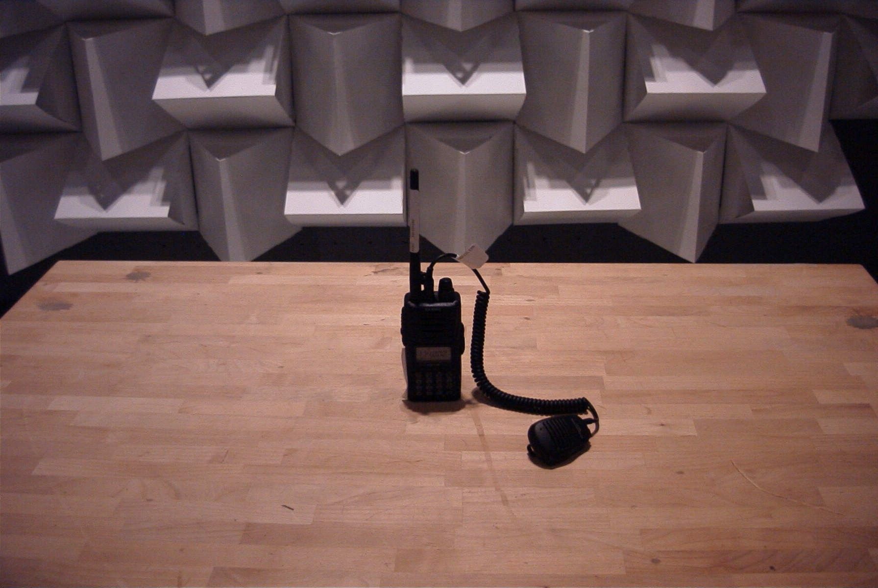
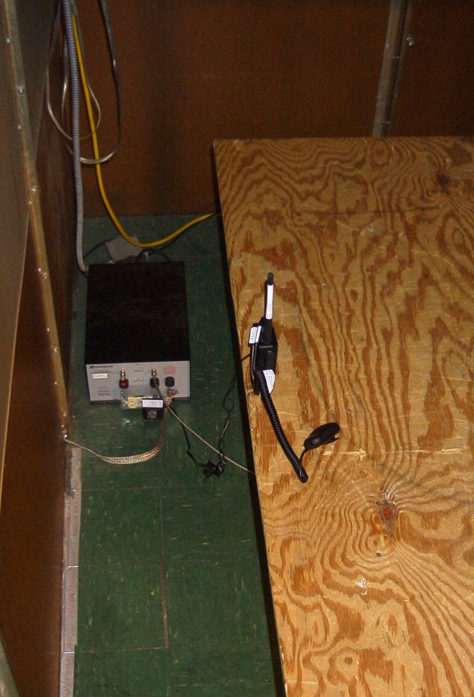
APPLICANT: VERTEX STANDARD CO., LTD. FCC ID: K6620223X20 REPORT #: U:\V\VERTEX\537AUT5\537AUT5TestReport.doc TABLE OF CONTENTS LIST TABLE OF CONTENTS LIST APPLICANT: VERTEX STANDARD CO., LTD. FCC ID: K6620223X20 TEST REPORT CONTAINING: PAGE 1-6....TEST EQUIPMENT LIST PAGE 7......TEST PROCEDURE PAGE 8......RADIATION INTERFERENCE TEST DATA PAGE 9......38 dB Rejection Ratio PAGE 10.....POWERLINE CONDUCTED PAGE 11.....POWERLINE CONDUCTED PLOTS EXHIBITS CONTAINING: REQUEST FOR CONFIDENTIALITY LETTER STATEMENT PER 15.121(a) BLOCK DIAGRAM SCHEMATIC INSTRUCTION MANUAL SAMPLE OF FCC ID LABEL AND SKETCH OF LOCATION RADIATED TEST SETUP PHOTOGRAPH POWERLINE CONDUCTED TEST SETUP PHOTOGRAPH EXTERNAL PHOTOS INTERNAL PHOTOS TUNING PROCEDURE CIRCUIT DESCRIPTION APPLICANT: VERTEX STANDARD CO., LTD. FCC ID: K6620223X20 REPORT #: U:\V\VERTEX\537AUT5\537AUT5TestReport.doc Page 1 of 11 APPLICANT: VERTEX STANDARD CO., LTD. FCC ID: K6620223X20 TEST EQUIPMENT LIST Device Manufacturer Model Serial Number Cal/Char Date Due Date or Status 3-Meter OATS TEI N/A N/A Listed 1/13/03 1/12/06 3/10-Meter OATS TEI N/A N/A Listed 3/27/04 3/26/07 Tan Tower Spectrum Analyzer HP 8566B Opt 462 3138A07786 3144A20661 CAL 9/23/03 9/23/05 Tan Tower RF Preselector HP 85685A 3221A01400 CAL 9/23/03 9/23/05 Tan Tower Quasi- Peak Adapter HP 85650A 3303A01690 CAL 9/23/03 9/23/05 Tan Tower Preamplifier HP 8449B-H02 3008A00372 CAL 9/23/03 9/23/05 Blue Tower Spectrum Analyzer HP 8568B 2928A04729 2848A18049 CAL 4/15/03 4/15/05 Blue Tower RF Preselector HP 85685A 2620A00294 CAL 4/27/04 4/27/06 Blue Tower Quasi- Peak Adapter HP 85650A 2811A01279 CAL 4/15/03 4/15/05 Silver Tower Spectrum Analyzer HP 8566B Opt 462 3552A22064 3638A08608 CAL 3/22/04 3/22/06 Silver Tower RF Preselector HP 85685A 2926A00983 CAL 3/22/04 3/22/06 Silver Tower Quasi- Peak Adapter HP 85650A 3303A01844 CAL 3/22/04 3/22/06 Silver Tower Preamplifier HP 8449B 3008A01075 CAL 3/22/04 3/22/06 Biconnical Antenna Electro- Metrics BIA-25 1171 CAL 4/26/01 4/26/03 Biconnical Antenna Eaton 94455-1 1096 CAL 8/17/04 8/17/06 Biconnical Antenna Eaton 94455-1 1057 CAL 3/18/03 3/18/05 BiconiLog Antenna EMCO 3143 9409-1043 No Cal Required Log-Periodic Electro-LPA-25 1122 CAL 8/26/06 APPLICANT: VERTEX STANDARD CO., LTD. FCC ID: K6620223X20 REPORT #: U:\V\VERTEX\537AUT5\537AUT5TestReport.doc Page 2 of 11 Device Manufacturer Model Serial Number Cal/Char Date Due Date or Status Antenna Metrics 8/26/04 Log-Periodic Antenna Electro- Metrics LPA-30 409 CAL 3/4/03 3/4/05 Log-Periodic Antenna Eaton 96005 1243 CAL 5/8/03 5/8/05 Dipole Antenna Kit Electro- Metrics TDA-30/1-4 152 CAL 3/21/01 3/21/04 Dipole Antenna Kit Electro- Metrics TDA-30/1-4 153 CAL 9/26/02 9/26/05 Double-Ridged Horn Antenna Electro- Metrics RGA-180 2319 CAL 2/17/03 2/17/05 Horn Antenna *(at 3 meters) Electro- Metrics EM-6961 6246 CAL 3/31/03 3/31/05 Horn Antenna *(at 10 meters) Electro- Metrics EM-6961 6246 CAL 6/4/03 6/4/05 Passive Loop Antenna EMC Test Systems EMCO 6512 9706-1211 CHAR 7/10/01 7/10/03 Harmonic Mixer with Horn Antenna Oleson Microwave Labs M08HW/A F30425-1 CHAR 4/25/03 4/25/05 Harmonic Mixer with Horn Antenna Oleson Microwave Labs M12HW/A E30425-1 CHAR 4/25/03 4/25/05 LISN Electro- Metrics ANS-25/2 2604 CAL 8/27/04 8/27/06 LISN Electro- Metrics EM-7820 2682 CAL 3/12/03 3/12/05 Termaline Wattmeter Bird Electronic Corporation 611 16405 CAL 7/16/04 7/16/06 Termaline Wattmeter Bird Electronic Corporation 6104 1926 CAL 7/16/04 7/16/06 Oscilloscope Tektronix 2230 300572 CAL 7/3/03 7/3/05 System One Audio Precision System One SYS1-45868 CHAR 4/25/02 4/25/04 Temperature Chamber Tenney Engineering TTRC 11717-7 CHAR 1/22/02 1/22/04 AC Voltmeter HP 400FL 2213A14499 CAL 7/19/04 7/19/06 AC Voltmeter HP 400FL 2213A14261 CHAR 10/15/01 10/15/03 AC Voltmeter HP 400FL 2213A14728 CHAR 10/15/01 10/15/03 Digital Multimeter Fluke 77 35053830 CHAR 1/8/02 1/8/04 Digital Multimeter Fluke 77 43850817 CHAR 1/8/04 APPLICANT: VERTEX STANDARD CO., LTD. FCC ID: K6620223X20 REPORT #: U:\V\VERTEX\537AUT5\537AUT5TestReport.doc Page 3 of 11 Device Manufacturer Model Serial Number Cal/Char Date Due Date or Status 1/8/02 Digital Multimeter HP E2377A 2927J05849 CHAR 1/8/02 1/8/04 Multimeter Fluke FLUKE-77-3 79510405 CHAR 9/26/01 9/26/03 Peak Power Meter HP 8900C 2131A00545 CAL 7/2/03 7/2/05 Power Sensor Agilent Technologies 84811A 2551A02705 CAL 7/2/03 7/2/05 Power Meter HP 432A 1141A07655 CAL 4/15/03 4/15/05 Power Sensor HP 478A 72129 CAL 4/15/03 4/15/05 Power Meter And Sensor Bird 4421-107 & 4022 0166 & 0218 CAL 4/16/03 4/16/05 Digital Thermometer Fluke 2166A 42032 CAL 7/19/04 7/19/06 Thermometer Traulsen SK-128 CHAR 1/22/02 1/22/04 Thermometer Extech 4028 14871-2 CAL 3/7/03 3/7/05 Hygro-Thermometer Extech 445703 0602 CAL 10/4/02 10/4/04 Frequency Counter HP 5352B 2632A00165 CAL 8/3/04 8/3/06 Frequency Counter HP 5385A 2730A03025 CAL 3/7/03 3/7/05 Service Monitor IFR FM/AM 500A 5182 CAL 11/22/00 Out of Service Comm. Serv. Monitor IFR FM/AM 1200S 6593 CAL 5/12/02 5/12/04 Signal Generator HP 8640B 2308A21464 CAL 8/26/04 8/26/06 Sweep Generator Wiltron 6648 101009 CAL 4/15/03 4/15/05 Sweep Generator Wiltron 6669M 007005 CAL 3/3/03 3/3/05 Modulation Analyzer HP 8901A 3435A06868 CAL 9/5/01 9/5/03 Modulation Meter Boonton 8220 10901AB CAL 4/15/03 4/15/05 Near Field Probe HP HP11940A 2650A02748 CHAR 2/1/01 Out of Service BandReject Filter Lorch Microwave 5BR4- 2400/60-N Z1 CHAR 4/17/03 4/17/05 BandReject Filter Lorch 6BR6-Z1 CHAR 4/17/05 APPLICANT: VERTEX STANDARD CO., LTD. FCC ID: K6620223X20 REPORT #: U:\V\VERTEX\537AUT5\537AUT5TestReport.doc Page 4 of 11 Device Manufacturer Model Serial Number Cal/Char Date Due Date or Status Microwave 2442/300-N 4/17/03 BandReject Filter Lorch Microwave 5BR4- 10525/900-S Z1 CHAR 4/12/03 4/12/05 Notch Filter Lorch Microwave 5BRX- 850/X100-N AD-1 CHAR 4/17/03 4/17/05 High Pass Filter Unk 3768(5)-400 041 CHAR 12/17/02 12/17/04 High Pass Filter Microlab HA-10N CHAR 11/17/02 11/17/04 High Pass Filter Microlab HA-20N CHAR 12/…
Text truncated - open the document above for the full version.
Contact Information
Applicant
Masatoshi Muraishi(Engineering Division)
Test Firm
Timco Engineering, Inc.S Sanders
Technical Specifications
| # | Rule Parts | Frequency Range | Power Output |
|---|---|---|---|
| 1 | 15B | 137 MHz - 174 MHz | - |
Other Applications from Yaesu Musen Co., Ltd.
K660E180X10
Dec 01, 2025BLUETOOTH MICROPHONE
Equipment Class
DTS - Digital Transmission System
K6630673Y3D
Aug 01, 2024VHF FM Marine Transceiver
Equipment Class
CXX - Communications Rcvr for use w/ licensed Tx and CBs
K6630653Y3D
Aug 01, 2024VHF FM Marine Transceiver
Equipment Class
CXX - Communications Rcvr for use w/ licensed Tx and CBs
K6630683X30
Jan 10, 2023VHF FM Marine Transceiver
Equipment Class
TNF - Licensed Non-Broadcast Transmitter Held to Face
K6650033X30
Nov 18, 2020Airband Radio Transceiver
Equipment Class
TNF - Licensed Non-Broadcast Transmitter Held to Face