K6620251X50HF Transceiver with Scanning Receiver
Yaesu Musen Co., Ltd.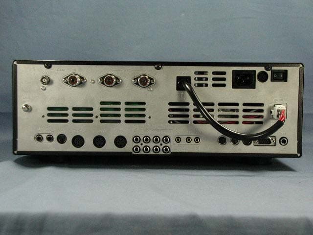
Click to zoom
Application Details
- Equipment Class
- JBP - Part 15 Class B Computing Device Peripheral
- Date of Grant
- Jun 13, 2006
- Application Purpose
- Original Equipment
- Date of Application
- Jun 13, 2006
- Equipment Note
- HF Transceiver with Scanning Receiver
- Company
- Yaesu Musen Co., Ltd.
- Country
- Japan
Documents & Files
Document Text
Text extracted from the exhibit documents filed with the FCC. Open a document above to read the original.
Users Manual
FT-2000 Operating Manual Vertex Standard Co., Ltd. 1 General Description We wish to take this opportunity to thank you for your purchase of the FT-2000 Transceiver! About This Manual . . . The FT-2000 is a leading-edge transceiver with a number of new and exciting features, some of which may be unfamiliar to you. In order to gain the most enjoyment and operating efficiency from your FT-2000, we recommend that you read this manual in its entirety, and keep it handy for reference as you explore the many capabilities of your new transceiver. Before using your FT-2000, be sure to read and follow the instructions in the “Before You Begin” section of this manual. Accessories & Options Supplied Accessories AC Power Cord 1 pc T9017882: USA T9013285: Europe T9013283A: Australia 4-pin DIN Plug 1 pc P0091004 5-pin DIN Plug 1 pc P0091006 8-pin DIN Plug 1 pc P0090651 1/4-inch 3-contact Plug 2 pcs P0090008 3.5 mm 3-contact Plug 1 pcs P0091046 3.5 mm 2-contact Plug 2 pcs P0090034 RCA Plug 6 pcs P0091365 Operating Manual 1 pc Warranty Card 1 pc Available Options MD-200A8X Ultra-High-Fidelity Desk-Top Microphone MD-100A8X Desk-Top Microphone YH-77STA Lightweight Stereo Headphone SP-2000 External Speaker with Audio Filter VL-1000/VP-1000 Linear Amplifier/AC Power Supply DMU-2000 Data Management Unit FT-2000 Operating Manual Vertex Standard Co., Ltd. 2 MTU-160 RF μ-Tuning Unit A (160 m Band) MTU-80/40 RF μ-Tuning Unit B (80/40 m Bands) MTU-30/20 RF μ-Tuning Unit C (30/20 m Bands) FH-2 Remote Control Keypad YF-122C Collins CW Filter (500 Hz/2 kHz: –6 dB/–60 dB) YF-122CN Collins CW Filter (300 Hz/1 kHz: –6 dB/–60 dB) Before You Begin Connecting AC Power Before connecting the AC power, check the label on the rear panel which indicates the AC mains voltage for which your transceiver is currently set. If the voltage on this label does not much your AC mains voltage, a switch on the internal power supply in the transceiver must be moved. This requires only a screwdriver and is not difficult (see below), but you should make sure the power supply is set up correctly before connecting power. Always uses the 10 A fuse in the fuse holder on the rear panel whether operate on 100 - 120 VAC or 200 - 240 VAC. Do not use the improper fuse. If you have any doubts about the procedure, contact your dealer for assistance. After making certain the AC voltage for which the transceiver is set matches your mains voltage, connect the AC power cord to the 3-pin AC jack on the rear panel. Wait until all other transceiver interconnections have been made before connecting the other end of the power cord to the wall outlet. CAUTION Permanent damage will result if improper AC supply voltage is applied to the transceiver. Your warranty does not cover damage caused by application of improper supply voltage, or use of an improper fuse. AC Input Voltage Selection Make certain that all cables are disconnected from the transceiver. Remove the three screws from each side of the transceiver, and three screws from the top edge of the rear panel. Slide the top cover toward to the rear about 1/2 inch (1 cm), then remove the top cover. Locate the power supply unit and the voltage selector switch. Move the AC range switch to the “115” position for operation from 100 - 120 VAC, or to the “230” position for operation from 200 - 240 VAC. FT-2000 Operating Manual Vertex Standard Co., Ltd. 3 Replace the top cover and its nine screws. Always uses the 10 A fuse in the fuse holder on the rear panel whether operate on 100 - 120 VAC or 200 - 240 VAC. Change the voltage marking on the label on the rear panel to match the new voltage setting. Extending the Front Feet In order to elevate the front panel for easy viewing, the front left and right feet of the bottom case may be extended. Pull the front legs outward from the bottom panel. Rotate the legs counter-clockwise to lock them in the extended position. Be sure the legs have locked securely in place, because the transceiver is quite heavy and an unlocked leg could result in damage, should the transceiver move suddenly. Retracting the Front Feet Rotate the legs clockwise, and push them inward while rotating to the right. The front feel should now be locked in the retracted position. Adjusting the Main Tuning Dial Torque The torque (drag) of the Main Tuning Dial knob may be adjusted according to your preferences. Simply hold down the rear skirt of the knob, and while holding it in place rotate the knob itself to the right to reduce the drag or to the left to increase the drag. Resetting the Microprocessor Resetting Memories (Only) Use this procedure to reset (clear out) the Memory channels previously stored, without affecting any configuration changes you may have made to the Menu settings. 1. Press the front panel’s [POWER] switch to turn the transceiver off. 2. Press and hold in the [A>M] button; while holding it in, press and hold in the front panel’s [POWER] switch to turn the transceiver on. Once the transceiver comes on, you may release the [A>M] button. Menu Resetting Use this procedure to restore the Menu settings to their factory defaults, without affecting the memories you have programmed. 1. Press the front panel’s [POWER] switch to turn the transceiver off. FT-2000 Operating Manual Vertex Standard Co., Ltd. 4 2. Press and hold in the [MENU] button; while holding it in, press and hold in the front panel’s [POWER] switch to turn the transceiver on. Once the transceiver comes on, you may release the [MENU] button. Full Reset Use this procedure to restore all Menu and Memory settings to their original factory defaults. All Memories will be cleared out by this procedure. 1. Press the front panel’s [POWER] switch to turn the transceiver off. 2. Press and hold in the [FAST] and [LOCK] buttons; while holding them in, press and hold in the front panel’s [POWER] switch to turn the transceiver on. Once the transceiver comes on, you may release the other two switches. Installation and Int…
Text truncated - open the document above for the full version.
Attestation Statements
May 17, 2006 Federal Communications Commission Authorization and Evaluation Division, 7435 Oakland Mills Road Columbia, MD 21046 USA Re: FT-2000 (FCC ID: K6620251X50) Gentlemen: The scanner receiver equipment meets the requirements of the FCC Rules, 15.121(a). Compliance is achieved through the following methods: The scanner receiver in this equipment is incapable of tuning, or readily being altered, by the User to operate within the frequency bands allocated to the Domestic Public Cellular Telecommunications Service in Part 22. Blocking of the cellular frequencies is implemented in the firmware of the unit’s main control central processing unit (CPU). Coverage of 824 – 849 MHz and 869 – 894 MHz is completely blocked, since it is done in the microprocessor, and cannot be re-enabled by any user-accessible procedure, including diode, resistor, or jumper changes, nor by connection of any external device such as a personal computer, nor by installation of any “special” enabling semiconductor device. Sincerely, Vertex Standard Co., Ltd. Mr. Moto Kurihara Group Leader of Engineering Division May 17, 2006 PCTEST Engineering Laboratory, Inc. 6660-B Dobbin Road Columbia, MD 21045 Attention: Authorization and Evaluation Division Reference: FT-2000 (FCC ID: K6620251X50) Pursuant to Sections 0.457 (d)(1)(ii) and 0.459 of the Commission’s Rules, the Applicant hereby requires confidential treatment of some of the information accompanying this Application, as listed below: ・ Block Diagram ・ Schematics ・ Circuit Description ・ Internal Photographs These materials contain trade secrets and proprietary information not customarily released to the public. The public disclosure of these matters might be harmful to the Applicant and provide unjustified benefits to its competitors. The Applicant understands that pursuant to Rule 0.457 (d)(1)(ii), disclosure of the Application and all accompanying documentation will not be made before the date of Grant for this Application. Sincerely, Vertex Standard Co., Ltd. Mr. Moto Kurihara Group Leader of Engineering Division May 17, 2006 Federal Communications Commission Authorization and Evaluation Division, 7435 Oakland Mills Road Columbia, MD 21046 USA Re: FT-2000 (FCC ID: K6620251X50) Gentlemen: A. Part 15.21 Compliance Statement Drawing: Part 15.21: Changes or modifications to this device not expressly approved by Vertex Standard could void the user’s authorization to operate this device. 20mm 97mm B. Part 15.21 Compliance Statement Drawing Location: IN OPERATION MANUAL (location on inside back cover) Sincerely, Vertex Standard Co., Ltd. Mr. Moto Kurihara Group Leader of Engineering Division May 17, 2006 Federal Communications Commission Authorization and Evaluation Division, 7435 Oakland Mills Road Columbia, MD 21046 USA Re: FT-2000 (FCC ID: K6620251X50) Gentlemen: Part 15.19 Compliance Statement is placed on the rear of case. Sincerely, Vertex Standard Co., Ltd. Mr. Moto Kurihara Group Leader of Engineering Division May 17, 2006 PCTEST Engineering Laboratory, Inc. 6660-B Dobbin Road Columbia, MD 21045 RE: LETTER OF AGENT AUTHORIZATION To Whom It May Concern: We, the undersigned, hereby authorize ETL SEMKO Japan K. K. to act on our behalf in all matters relating to application for equipment authorization, including the signing of all documents relating to these matters. We also hereby certify that no party to the application authorized hereunder is subject to the denial of benefits, including FCC benefits, pursuant to Section 5301 of the Anti-Drug Abuse Act of 1988,21 U.S.C.862. This agreement expires one year from the current date. Sincerely, Vertex Standard Co., Ltd. Mr. Moto Kurihara Group Leader of Engineering Division
External Photos
FCC ID: K6620251X50 IC ID: 511B-20251X50 Front view Rear view Vertex Standard Co., Ltd. FCC ID: K6620251X50 IC ID: 511B-20251X50 Top view Bottom view Vertex Standard Co., Ltd. FCC ID: K6620251X50 IC ID: 511B-20251X50 Left side view Right side view Vertex Standard Co., Ltd.
ID Label/Location Info
FT-2000FT-2000 LABEL DRAWINGLABEL DRAWING Vertex Standard Co., Ltd.Vertex Standard Co., Ltd. ID / Part 15.19 and CAUTION drawings ID drawing Part 15.19 and CAUTION drawings Label location FT-2000 FCC ID: K6620251X50 IC: 511B-20251X50
Test Report
Report No. ESJ–106074 FCC ID : K6620251X50 / IC : 511B-20251X50 © ETL SEMKO Japan K.K. Page 1 of 44 Version 0.0 CERTIFICATE OF COMPLIANCE Regulation : FCC Part15B – Scanning Receiver Industry Canada RSS-215 Issue 1 : FCC Part15B Class B CANADA ICES-003 Class B Applicant Testing Laboratory Vertex Standard Co., Ltd. 4-8-8 Nakameguro Meguro-ku, Tokyo 153-8644 Japan Tel : +81 3 5725 6111 Fax : +81 3 5725 6225 ETL SEMKO Japan K.K. Kashima Site 3-2 Sunayama, Kamisu, Ibaraki 314-0255 Japan Tel.: +81 479 40 1097 Fax.: +81 479 46 1788 URL: http://www.japan.intertek-etlsemko.com Equipment Type HF Transceiver Category Scanning Receiver & Peripherals Trademark YA E S U Model (s) FT-2000 Serial No. 6G000001 FCC ID K6620251X50 IC 511B-20251X50 Test Result Complied Report Number ESJ-106074 Report Issue Date May 31, 2006 This equipment has been shown to be capable of compliance with the applicable standard(s) as indicated in the test report. I attest to the accuracy of data. All measurements reported herein were performed by me or were made under my supervision and are correct to the best of my knowledge and belief. I assume full responsibility for the completeness of these measurements and vouch for the qualifications of all persons taking them. This test report shall not be reproduced partially, or in full, without the prior written approval of ETL SEMKO Japan K.K. The results and statements contained in this report pertain only to the equipment evaluated. Approved by Tested by Kazuo Gokita [ Assistant Manager ] Kazuo Masuda Report No. ESJ–106074 FCC ID : K6620251X50 / IC : 511B-20251X50 © ETL SEMKO Japan K.K. Page 2 of 44 Version 0.0 TABLE OF CONTENTS Page SECTION 1. GENERAL INFORMATION ........................................................................................................... 3 SECTION 2. SUMMARY OF TEST RESULTS ...................................................................................................4 SECTION 3. INFORMATION ABOUT EUT ....................................................................................................... 5 SECTION 4. SUPPORT EQUIPMENT(S) ............................................................................................................ 7 SECTION 5. USED CABLE (S)............................................................................................................................ 8 SECTION 6. CONSTRUCTION OF EQUIPMENT ........................................................................................... 10 SECTION 7. OPERATING CONDITION........................................................................................................... 12 SECTION 8. TEST PROCEDURE(S) ................................................................................................................. 13 SECTION 9. EVALUATION OF TEST RESULTS............................................................................................. 18 SECTION 10. LIST OF MEASURING INSTRUMENTS .................................................................................... 41 SECTION 11. MEASUREMENT UNCERTAINTY ............................................................................................. 43 SECTION 12. DESCRIPTION OF TEST LABORATORY .................................................................................. 44 Report No. ESJ–106074 FCC ID : K6620251X50 / IC : 511B-20251X50 © ETL SEMKO Japan K.K. Page 3 of 44 Version 0.0 SECTION 1. GENERAL INFORMATION TEST PERFORMED Location Kashima No.1 Test Site (FCC Reg. : 934283) (IC File No. : IC 2065-1 ) EUT Received May 22, 2006 Te s t St a r t e d May 22, 2006 Te s t C o m p l e t e d May 24, 2006 Standard Applied FCC Part15B – Scanning Receiver Industry Canada RSS-215 Issue 1 FCC Part15B Class B - Peripherals and Canada ICES-003 Class B Test Setup ANSI C63.4-2003 Deviation from Standard (s) No deviation TEST TRACEABILITY Traceability to national standards of test result is achieved by means of calibration traceability to national or international standards. LIMITATIONS ON RESULTS The test result of this report is effective for equipment under test itself and under the test configuration described on the report. This test report does not assure that whether the test result taken in other testing laboratory is compatible or reproducible to the test result on this report or not. ABBREVIATIONS AE = Associated Equipment DIP = Dipole Antenna AMN = Artificial Mains Network DoC = Device for Declaration of Conformity AMP = Amplifier, ATT = Attenuato r EUT = Equipment Under Test ANT = Antenna, BBA = Broadband Antenna ISN = Impedance Stabilization Network AVG = Average LISN = Line Impedance Stabilization Network Cal = Calibration PK = Peak CDN = Coupling Decoupling Network Q-P = Quasi-peak LCD = Liquid-Crystal Display RX = Receive SPKR = Speaker Report No. ESJ–106074 FCC ID : K6620251X50 / IC : 511B-20251X50 © ETL SEMKO Japan K.K. Page 4 of 44 Version 0.0 SECTION 2. SUMMARY OF TEST RESULTS This test report clearly shows that the EUT is in compliance with the FCC Part15B (- Scanning Receiver with Industry Canada RSS-215) and FCC Part15B Class B (- Peripheral with Canada ICES-003 Class B) specification. The minimum margins to the limits are as follows: Conducted Voltages on Mains Port RX 0.030MHz mode 9.4 dB at 0.3975 MHz Radiated Electric Field RX 60MHz mode 8.6 dB at 576.05 MHz Conducted Power on Antenna Port RX 60MHz mode (ANT2) 22.6 dB at 1808.24 MHz 38dB Rejection Test (15.121(b)) No frequency of response was detected. - Passed - Note : See Section 9 for details. Report No. ESJ–106074 FCC ID : K6620251X50 / IC : 511B-20251X50 © ETL SEMKO Japan K.K. Page 5 of 44 Version 0.0 SECTION 3. INFORMATION ABOUT EUT The equipment under test (EUT) consisted of the following equipment. 3.1 List of System Configuration Symbol Item Model No. Serial No. Manufacturer Notes FCC ID A1 HF Transceiver FT-2000 6G000001 Vertex Standard EUT K6620251X50 A2 Microphone MH-31B8 None Vertex Standard EUT N.A. A3 Headphone YH-7…
Text truncated - open the document above for the full version.
Test Setup Photos
Report No. ESJ–106074 FCC ID : K6620251X50 / IC : 511B-20251X50 © ETL SEMKO Japan K.K. Page 1 of 4 Version 0.0 Annex A Photographs Report No. ESJ–106074 FCC ID : K6620251X50 / IC : 511B-20251X50 © ETL SEMKO Japan K.K. Page 2 of 4 Version 0.0 PHOTOGRAPHS OF MAXIMUM EMISSION SET-UP 1 Conducted Voltages on Mains Port Note : Maintaining 10cm spacing between all the equipment cabinets. Report No. ESJ–106074 FCC ID : K6620251X50 / IC : 511B-20251X50 © ETL SEMKO Japan K.K. Page 3 of 4 Version 0.0 2 Radiated Electric Field Note : Maintaining 10cm spacing between all the equipment cabinets. Report No. ESJ–106074 FCC ID : K6620251X50 / IC : 511B-20251X50 © ETL SEMKO Japan K.K. Page 4 of 4 Version 0.0 3 Conducted Power on Antenna Port 4 38dB Rejection
Contact Information
Applicant
Masatoshi Muraishi(Engineering Division)
Technical Contact
PCTEST Engineering Laboratory, Inc.Randy Ortanez
[email protected]410-290-6652
6660-B Dobbin Road · Columbia, Maryland · United States
Test Firm
Intertek Japan K.K. Kashima SiteTakeshi Yamanaka
Technical Specifications
| # | Rule Parts | Frequency Range | Power Output |
|---|---|---|---|
| 1 | 15B | - | - |
Other Applications from Yaesu Musen Co., Ltd.
K660E180X10
Dec 01, 2025BLUETOOTH MICROPHONE
Equipment Class
DTS - Digital Transmission System
K6630673Y3D
Aug 01, 2024VHF FM Marine Transceiver
Equipment Class
CXX - Communications Rcvr for use w/ licensed Tx and CBs
K6630653Y3D
Aug 01, 2024VHF FM Marine Transceiver
Equipment Class
CXX - Communications Rcvr for use w/ licensed Tx and CBs
K6630683X30
Jan 10, 2023VHF FM Marine Transceiver
Equipment Class
TNF - Licensed Non-Broadcast Transmitter Held to Face
K6650033X30
Nov 18, 2020Airband Radio Transceiver
Equipment Class
TNF - Licensed Non-Broadcast Transmitter Held to Face