K6620275X40SCANNING RECEIVER
Yaesu Musen Co., Ltd.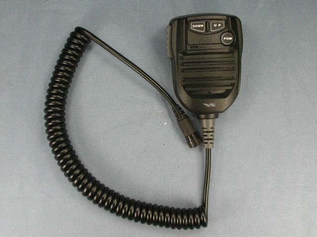
Click to zoom
Application Details
- Equipment Class
- CSR - Scanning Receiver
- Date of Grant
- Feb 14, 2007
- Application Purpose
- Original Equipment
- Date of Application
- Feb 14, 2007
- Equipment Note
- SCANNING RECEIVER
- Frequency Range
- 894.00000000 - 960.00000000
- Company
- Yaesu Musen Co., Ltd.
- Country
- Japan
Documents & Files
Document Text
Text extracted from the exhibit documents filed with the FCC. Open a document above to read the original.
Users Manual
FCC ID: K6620275X40 IC ID: 511B-20275X40 FTM-10R Operating Manual Accessories & Options Supplied Accessories Mobile Mounting Bracket DC Power Cord W/Fuse Spare Fuse 15 A Angle Sub Panel Hex Wrench Operating Manual Warranty Card Optional Accessories DTMF Microphone MH-68A6J Normal Microphone MH-68B6J Panel Separation Kit YSK-M10 Bluetooth Head Set BH-1 Bluetooth Adapter Unit BU-1 Head Set Charger Sleeve CAB-1 Microphone Jack MEK-M10 Ear Phone for BH-1 FEP-4 High-Power External Speaker MLS-200-M10 AC Power Supply (25 A) FP-1025A AC Power Supply (30 A) FP-1030A Availability of accessories may vary. Some accessories are supplied as standard per local requirements, while others may be unavailable in some regions. This product is designed to perform optimally when used with genuine Vertex Standard accessories. Vertex Standard shall not be liable for any damage to this product and/or accidents such as fire, leakage or explosion of a battery pack, etc., caused by the malfunction of non- Vertex Standard accessories. Consult your Vertex Standard dealer for details regarding these and any newly-available options. Connection of any non-Vertex Standard-approved accessory, should it cause damage, may void the Limited Warranty on this apparatus. Vertex Standard Co., Ltd. 1 FCC ID: K6620275X40 IC ID: 511B-20275X40 FTM-10R Operating Manual Installation This chapter describes the installation procedure for integrating the FTM-10R into a typical amateur radio station. It is presumed that you possess technical knowledge and conceptual understanding consistent with your status as a licensed radio amateur. Please take some extra time to make certain that the important safety and technical requirements detailed in this chapter are followed closely. Preliminary Inspection Inspect the transceiver visually immediately upon opening the packing carton. Confirm that all controls and switches work freely, and inspect the cabinet for any damage. Gently shake the transceiver to verify that no internal components have been shaken loose due to rough handling during shipping. If any evidence of damage is discovered, document it thoroughly and contact the shipping company (or your local dealer, if the unit was purchased over-the-counter) so as to get instructions regarding the prompt resolution of the damage situation. Be certain to save the shipping carton, especially if there are any punctures or other evidence of damage incurred during shipping; if it is necessary to return the unit for service or replacement, use the original packing materials but put the entire package inside another packing carton, so as to preserve the evidence of shipping damage for insurance purposes. Installation Tips To ensure long life of the components, be certain to provide adequate ventilation around the cabinet of the FTM-10R. Do not install the transceiver on top of another heat-generating device (such as a power supply or amplifier), and do not place equipment, books, or papers on top of the FTM-10R. Avoid heating vents and window locations that could expose the transceiver to excessive direct sunlight, especially in hot climates. The FTM-10R should not be used in an environment where the ambient temperature exceeds +140 °F (+60 °C). Safety Information The FTM-10R is an electrical apparatus, as well as a generator of RF (Radio Frequency) energy, and you should exercise all safety precautions as are appropriate for this type of device. These safety tips apply to any device installed in a well-designed amateur radio station. (!) Never allow unsupervised children to play in the vicinity of your transceiver or Vertex Standard Co., Ltd. 2 FCC ID: K6620275X40 IC ID: 511B-20275X40 FTM-10R Operating Manual antenna installation. (!) Be certain to wrap any wire or cable splices thoroughly with insulating electrical tape, to prevent short circuits. (!) Do not route cables or wires through door jambs or other locations where, through wear and tear, they may become frayed and shorted to ground or to each other. (!) Do not stand in front of a directional antenna while you are transmitting into that antenna. Do not install a directional antenna in any location where humans or pets may be walking in the main directional lobe of the antenna’s radiation pattern. (!) In mobile installations, it is preferable to mount your antenna on top of the roof of the vehicle, if feasible, so as to utilize the car body as a counterpoise for the antenna and raise the radiation pattern as far away from passengers as possible. (!) During vehicular operation when stopped (in a parking lot, for example), make it a practice to switch to Low power if there are people walking nearby. (!) Never wear dual-earmuff headphones while driving a vehicle. (!) Do not attempt to drive your vehicle while making a telephone call on an autopatch using the optional DTMF microphone. Pull over to the side of the road, whether dialing manually or using the auto-dial feature. Warning!: The 70.7 V RF voltage (@50 W/50 Ohms) is applied to the TX RF section of the transceiver while transmitting. Do not touch the TX RF section absolutely while transmitting. Antenna Considerations The FTM-10R is designed for use with antennas presenting an impedance of near 50 Ohms at all operating frequencies. The antenna (or a 50 Ohm dummy load) should be connected whenever the transceiver is turned on, to avoid damage that could otherwise result if transmission occurs accidentally without an antenna. Ensure that your antenna is designed to handle 50 Watts of transmitter power. Some magnetic-mount mobile antennas, designed for use with hand-held transceivers, may not be capable of withstanding this power level. Consult the antenna manufacturer’s specification sheet for details. Most all FM work is performed using vertical polarization. When installing a directional antenna such as a Yagi or Cubical Quad, be certain to orient it so as to produce vertical polarization, unless you are engaged in a special operating sit…
Text truncated - open the document above for the full version.
Attestation Statements
December 25, 2006 Federal Communications Commission Authorization and Evaluation Division, 7435 Oakland Mills Road Columbia, MD 21046 USA Re: FTM-10R (FCC ID: K6620275X40) Gentlemen: Part 15.19 Compliance Statement is placed on the left side of case. Sincerely, Vertex Standard Co., Ltd. Mr. Moto Kurihara Group Leader of Engineering Division
Attestation Statements
December 25, 2006 Federal Communications Commission Authorization and Evaluation Division, 7435 Oakland Mills Road Columbia, MD 21046 USA Re: FTM-10R (FCC ID: K6620275X40) Gentlemen: A. Part 15.21 Compliance Statement Drawing: Part 15.21: Changes or modifications to this device not expressly approved by Vertex Standard could void the user’s authorization to operate this device. 20mm 97mm B. Part 15.21 Compliance Statement Drawing Location: IN OPERATION MANUAL (location on inside back cover) Sincerely, Vertex Standard Co., Ltd. Mr. Moto Kurihara Group Leader of Engineering Division
Attestation Statements
December 25, 2006 Federal Communications Commission Authorization and Evaluation Division, 7435 Oakland Mills Road Columbia, MD 21046 USA Re: FTM-10R (FCC ID: K6620275X40) Gentlemen: The scanner receiver equipment meets the requirements of the FCC Rules, 15.121(a). Compliance is achieved through the following methods: The scanner receiver in this equipment is incapable of tuning, or readily being altered, by the User to operate within the frequency bands allocated to the Domestic Public Cellular Telecommunications Service in Part 22. Blocking of the cellular frequencies is implemented in the firmware of the unit’s main control central processing unit (CPU). Coverage of 824 – 849 MHz and 869 – 894 MHz is completely blocked, since it is done in the microprocessor, and cannot be re-enabled by any user-accessible procedure, including diode, resistor, or jumper changes, nor by connection of any external device such as a personal computer, nor by installation of any “special” enabling semiconductor device. Sincerely, Vertex Standard Co., Ltd. Mr. Moto Kurihara Group Leader of Engineering Division
External Photos
FCC ID: K6620275X40 IC ID: 511B-20275X40 Front view Rear view Vertex Standard Co., Ltd. FCC ID: K6620275X40 IC ID: 511B-20275X40 Top view Bottom view Vertex Standard Co., Ltd. FCC ID: K6620275X40 IC ID: 511B-20275X40 Left side view Right side view Vertex Standard Co., Ltd. FCC ID: K6620275X40 IC ID: 511B-20275X40 Microphone DC Cable Vertex Standard Co., Ltd.
ID Label/Location Info
FTM-10RFTM-10R LABEL DRAWINGLABEL DRAWING Vertex Standard Co., Ltd.Vertex Standard Co., Ltd. ID / Part 15.19 and CAUTION drawings ID drawing Part 15.19 and CAUTION drawings Label location FTM-10R VERTEX STANDARD CO., LTD. MADE IN JAPAN IC: 511B-20275X40 FCC ID: K6620275X40 4909959000000 SER NO. 00000000
Test Report
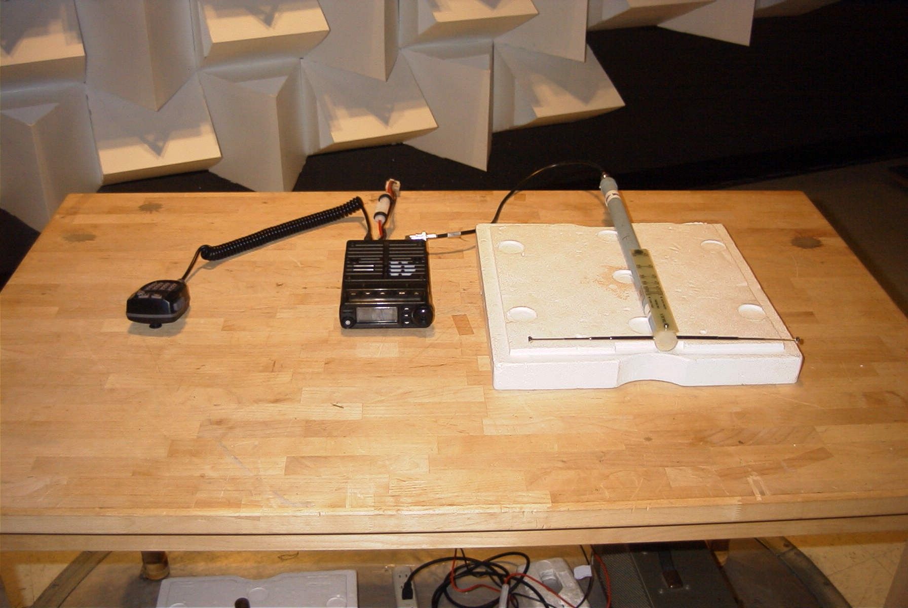
FCC PART 15 SCANNING RECEIVER Applicant VERTEX STANDARD CO., LTD. Address 4-8-8, NAKAMEGURO, MEGURO-KU TOKYO, 153-8644, JAPAN FCC ID: K6620275X40 Model Number FTM-10R Product Description SCANNING RECEIVER Date Sample Received JANUARY 11, 2007 Date Tested JANUARY 16, 2007 Tested By JOSEPH SCOGLO Approved By MARIO DE ARANZETA Report Number 90UT7TestReport.doc Total Pages 10 Test Results PASS FAIL THE ATTACHED REPORT SHALL NOT BE REPRODUCED EXCEPT IN FULL WITHOUT THE WRITTEN APPROVAL OF TIMCO ENGINEERING, INC. 849 NW State Road 45 Newberry, Fl 32669 USA Phone: 888.472.2424 or 352.472.5500 Fax: 352.472.2030 Email: [email protected] Website: www.timcoengr.com Certificate # 0955-01 APPLICANT: VERTEX STANDARD CO., LTD. FCC ID: K6620275X40 REPORT #: W:\V\VERTEX\90UT7\90UT7TestReport.doc Page 2 of 10 TABLE OF CONTENTS STATEMENT OF COMPLIANCE.................................................................................. 3 GENERAL INFORMATION .......................................................................................... 4 TEST EQUIPMENT LIST............................................................................................. 5 TEST PROCEDURE ................................................................................................... 6 RADIATED SPURIOUS EMISSIONS............................................................................ 7 POWER LINE CONDUCTED INTERFERENCE............................................................. 9 38 Db REJECTION RADIO ....................................................................................... 10 APPLICANT: VERTEX STANDARD CO., LTD. FCC ID: K6620275X40 REPORT #: W:\V\VERTEX\90UT7\90UT7TestReport.doc Page 3 of 10 STATEMENT OF COMPLIANCE This equipment has been tested in accordance with the standards identified in the referenced test report. To the best of my knowledge and belief, these tests were performed using the measurement procedures described in this report and demonstrate that the equipment complies with the appropriate standards. I attest that the necessary measurements were made by me or under my supervision, at TIMCO ENGINEERING, INC. located at 849 N.W. State Road 45, Newberry, Florida 32669 USA. Certificate #0955-01 Authorized by: Mario de Aranzeta Authorized Signature: < Mario de Aranzeta> Function: Engineer Date: 2/7/2007 APPLICANT: VERTEX STANDARD CO., LTD. FCC ID: K6620275X40 REPORT #: W:\V\VERTEX\90UT7\90UT7TestReport.doc Page 4 of 10 GENERAL INFORMATION The test results relate only to the items tested. DUT Description SCANNING RECEIVER FCC ID K6620275X40 Model Number FTM-10R 110–120Vac/50– 60Hz DC Power DUT Power Source Battery Operated Exclusively Prototype Pre-Production Test Item Production Modifications to DUT None Test Standards FCC Part 15, Subpart B, ANSI C63.4-2003 APPLICANT: VERTEX STANDARD CO., LTD. FCC ID: K6620275X40 REPORT #: W:\V\VERTEX\90UT7\90UT7TestReport.doc Page 5 of 10 TEST EQUIPMENT LIST Device Manufacturer Model Serial Number Cal/Char Date Due Date 3/10-Meter OATS TEI N/A N/A Listed 3/27/04 3/26/07 3-Meter OATS TEI N/A N/A Listed 1/11/06 1/10/09 Antenna: Biconnical Eaton 94455-1 1057 CAL 12/12/05 12/12/07 Antenna: Biconnical Eaton 94455-1 1096 CAL 10/11/06 10/11/08 Antenna: Biconnical Electro- Metrics BIA-25 1171 CAL 4/29/05 4/29/07 Analyzer Blue Tower Quasi-Peak Adapter HP 85650A 2811A01279 CAL 4/13/05 4/13/07 Analyzer Blue Tower RF Preselector HP 85685A 2926A00983 CAL 9/5/05 9/5/07 Analyzer Blue Tower Spectrum Analyzer HP 8568B 2928A04729 2848A18049 CAL 4/13/05 4/13/07 LISN Electro- Metrics ANS-25/2 2604 CAL 10/5/06 10/5/08 LISN Electro- Metrics EM-7820 2682 CAL 4/28/05 4/28/07 Antenna: Log- Periodic Eaton 96005 1243 CAL 12/14/05 12/14/07 APPLICANT: VERTEX STANDARD CO., LTD. FCC ID: K6620275X40 REPORT #: W:\V\VERTEX\90UT7\90UT7TestReport.doc Page 6 of 10 TEST PROCEDURE General: This report shall NOT be reproduced except in full without the written approval of TIMCO ENGINEERING, INC. Radiation Interference: The test procedure used was ANSI Standard C63.4-2003 using a spectrum analyzer with a pre-selector. The bandwidth of the spectrum analyzer was 100 kHz with an appropriate sweep speed. The analyzer was calibrated in dB above a microvolt at the output of the antenna. The video bandwidth was always greater than or equal to the RBW. Formula Of Conversion Factors: The Field Strength at 3m was established by adding the meter reading of the spectrum analyzer (which is set to read in units of dBuV) to the antenna correction factor supplied by the antenna manufacturer. The antenna correction factors are stated in terms of dB. The gain of the Preselector was accounted for in the Spectrum Analyzer Meter Reading. Example: Freq (MHz) Meter Reading + ACF +CL = FS 33 20 dBuV + 10.36 dB/m +0.40 dB =30.36 dBuV/m @ 3m ANSI C63.4-2003 Section 10.1.7 Measurement Procedures: The unit under test was placed on a table 80 cm high and with dimensions of 1mby 1.5m. The table used for radiated measurements is capable of continuous rotation. When an emission was found, the table was rotated to produce the maximum signal strength. At this point, the antenna was raised and lowered from 1m to 4m. The antenna was placed in both the horizontal and verticals planes. APPLICANT: VERTEX STANDARD CO., LTD. FCC ID: K6620275X40 REPORT #: W:\V\VERTEX\90UT7\90UT7TestReport.doc Page 7 of 10 RADIATED SPURIOUS EMISSIONS Rules Part No.: 15.109 Requirements: Frequency Limits 30 – 88 40.0 dBμV/m measured @ 3 meters 80 – 216 43.5 dBμV/m measured @ 3 meters 216 – 960 46.0 dBμV/m measured @ 3 meters Above 960 54.0 dBμV/m measured @ 3 meters Test Procedure: The procedure used was ANSI C63.4-2003. The frequency was scanned from 30 MHz to 1.0 GHz. When an emission was found, the table was rotated to produce the maximum signal strength. The DUT was measured in three (3) orthogonal planes. Test Data: Tuned Frequency MHz Emission Frequency MHz Meter Reading dBuV Ant. Pol Coax Loss dB Correction Factor dB Field Strength dBuV/m Margin …
Text truncated - open the document above for the full version.
Contact Information
Applicant
Masatoshi Muraishi(Engineering Division)
Test Firm
Timco Engineering, Inc.Sid Sanders
Technical Specifications
| # | Rule Parts | Frequency Range | Power Output |
|---|---|---|---|
| 12 | 15B | 894 MHz - 960 MHz | - |
Other Applications from Yaesu Musen Co., Ltd.
K660E180X10
Dec 01, 2025BLUETOOTH MICROPHONE
Equipment Class
DTS - Digital Transmission System
K6630673Y3D
Aug 01, 2024VHF FM Marine Transceiver
Equipment Class
CXX - Communications Rcvr for use w/ licensed Tx and CBs
K6630653Y3D
Aug 01, 2024VHF FM Marine Transceiver
Equipment Class
CXX - Communications Rcvr for use w/ licensed Tx and CBs
K6630683X30
Jan 10, 2023VHF FM Marine Transceiver
Equipment Class
TNF - Licensed Non-Broadcast Transmitter Held to Face
K6650033X30
Nov 18, 2020Airband Radio Transceiver
Equipment Class
TNF - Licensed Non-Broadcast Transmitter Held to Face