K6620285X20AMATEUR RADIO WITH SCANNING RECEIVER
Yaesu Musen Co., Ltd.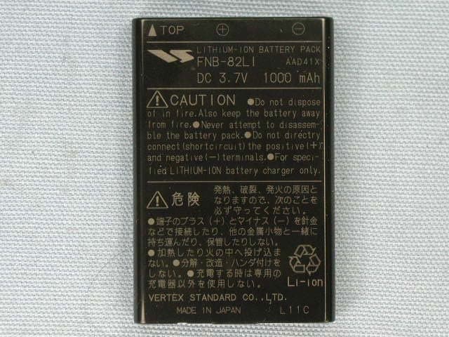
Click to zoom
Application Details
- Equipment Class
- CSR - Scanning Receiver
- Date of Grant
- May 14, 2007
- Application Purpose
- Original Equipment
- Date of Application
- May 13, 2007
- Equipment Note
- AMATEUR RADIO WITH SCANNING RECEIVER
- Frequency Range
- 894.00000000 - 960.00000000
- Company
- Yaesu Musen Co., Ltd.
- Country
- Japan
Documents & Files
Document Text
Text extracted from the exhibit documents filed with the FCC. Open a document above to read the original.
Users Manual
FCC ID: K6620285X20 IC ID: 511B-20285X20 VX-3R Operating Manual General Description The VX-3R is a micro-miniature multiband FM transceiver with extensive receive frequency coverage, providing local-area two-way amateur communications along with unmatched monitoring capability. The VX-3R’s incredibly small size allows you to take it anywhere - hiking, skiing, or while walking around town - and its operating flexibility brings the user many avenues of operating enjoyment. Its incredibly tiny FNB-82LI Lithium-Ion Battery Pack provides up to 1.5 Watts of transmit power on VHF, and 1 Watt on UHF. Besides 144- and 430-MHz transceive operation, the VX-3R provides receive coverage of the AM (MF) which provide the internal bar antenna and FM broadcast bands, HF Shortwave Bands, VHF and UHF TV bands, the VHF AM aircraft band, and a wide range of commercial and public safety frequencies! Furthermore, the VX-3R provides the internal bar antenna for the good receiving the AM broadcast. Additional features include an Enhanced Paging and Code Squelch (EPCS), which allows you to page a particular station and only receive calls from that station, if desired; a security Password feature, which will allow you to turn on and operate your transceiver only after you enter your Password; a convenient access key for Vertex Standard’s WIRES ™ (Wide-Coverage Internet Repeater Enhancement System); Emergency Automatic ID (EAI) function, that will automatically cause your VX-3R to transmit your callsign and engage your rig’s microphone, even if you are disabled and unable to press the PTT switch; a transmit Time-Out Timer (TOT); Automatic Power-Off (APO); Automatic Repeater Shift (ARS); Yaesu’s exclusive ARTS ™ (Auto-Range Transponder System) which “beeps” the user when you move out of communications range with another ARTS TM equipped station, plus provision for reduction of the TX deviation in areas of high channel congestion. And an S-meter squelch circuit allows the owner to set the squelch to open at a programmable setting of the S-Meter, thus reducing guesswork in setting the squelch threshold. We appreciate your purchase of the VX-3R, and encourage you to read this manual thoroughly, so as to learn about the many exciting features of your exciting new Yaesu hand-held transceiver! Accessories & Options Supplied Accessories FNB-82LI 3.7 V, 1000 mAh Rechargeable Lithium Ion Battery Pack NC-85A/B, C, U* 2.5-Hour Charger YHA-66 Antenna Operating Manual Warranty Card Available Options FNB-82LI 3.7 V, 1000 mAh Rechargeable Lithium Ion Battery Pack FBA-37 Dry Cell Battery Case for 3 x “AA” Alkaline Cells Vertex Standard Co., Ltd. 1 FCC ID: K6620285X20 IC ID: 511B-20285X20 VX-3R Operating Manual NC-85A/B, C, U* 2.5-Hour Charger CN-3 BNC-to-SMA Adapter CT-27 Cloning Cable CT-44 Microphone Adapter E-DC-21 DC Cable w/ Cigarette-Lighter Adapter MH-34B4B Speaker/Microphone MH-37A4B Earpiece/Microphone VC-25 VOX Headset * “A/B” suffix is for use with 100-120 VAC, “C” suffix is for use with 230-240 VAC, and “U” suffix is for use with 230 VAC. Availability of accessories may vary. Some accessories are supplied as standard per local requirements, while others may be unavailable in some regions. Consult your Yaesu dealer for details regarding these and any newly-available options Connection of any non-Yaesu-approved accessory, should it cause damage, may void the Limited Warranty on this apparatus. Control & Connections ANTENNA Jack Connect the supplied rubber flex antenna (or another antenna presenting a 50-Ohm impedance) here. MIC/SP Jack This four-conductor miniature jack provides connection points for microphone audio, earphone audio, PTT, and ground. DIAL Knob The main tuning Dial is used for setting the operating frequency, and also is used for audio volume level, menu selections, and other adjustments. To rotate this Dial knob, pull the knob to unlock the mechanical dial lock, and then rotate the Dial knob. TX/BUSY Indicator This indicator glows green when the squelch opens, and turns red during transmit. During “Emergency” operation (see page ??), this indicator will glow (or flash) white. PTT (Push To Talk) Switch Press this switch to transmit, and release it (to receive) after your transmission is completed. MONI Switch Pressing this key disables the noise squelching action, allowing you to hear very weak signals near the background noise level. Vertex Standard Co., Ltd. 2 FCC ID: K6620285X20 IC ID: 511B-20285X20 VX-3R Operating Manual POWER Switch Press and hold this switch in for one second to toggle the transceiver’s power on and off. KEYPAD These nine keys select many of most important operating features on the VX-3R. The functions of the keys are described in detail on the pages to follow. SPEAKER The internal speaker is located here. MIC The internal microphone is located here. EAR Jack This 3-pin miniature jack provides connection points for stereo earphone. This 3-pin miniature jack allows connection to stereo earphone. When insert the after-market stereo earphone into this jack, you may enjoy the FM broadcast with a stereo. EXT DC This coaxial DC jack allows connection to an external DC power source (2.5 - 7.0V DC). The center pin of this jack is the Positive (+) connection. Keypad Functions Key Primary Function (Press Key) Secondary Function (Press [FW] + Key) Third Function (Press and Hold Key) MODE Switches the operating mode. Activates CTCSS or DCS operation. Activates the Smart Search ™ and Channel Counter features. BAND Moves operation to the next-highest frequency band. Activates the “Memory Bank” feature while in the Memory Recall mode. Moves operation to the next-lowest frequency band. Holding this key after pressing the [FW] key to activates the key lockout feature. Activates the Scanner Upward (toward a higher frequency or a higher channel number). TXPO Switches the transmit power output between “HI” and “LOW.” Selects the synthesizer steps to be used during VFO operati…
Text truncated - open the document above for the full version.
Attestation Statements
April 13, 2007 Federal Communications Commission Authorization and Evaluation Division, 7435 Oakland Mills Road Columbia, MD 21046, USA Re: VX-3R (FCC ID: K6620285X20) Gentlemen: A. Part 15.19 & 15.21 Compliance Statement Drawing: B. Part 15.19 & 15.21 Compliance Statement Drawing Location: IN OPERATION MANUAL (location on inside back cover) Sincerely, Vertex Standard Co., Ltd. Mr. Moto Kurihara Group Leader of Engineering Division 1. Changes or modifications to this device not expressly approved Yaesu Musen could void the user’s authorization to operate this device. 2. This device complies with part 15 of the FCC rules. Operation is subject to the following two conditions; (1) This device may not cause harmful interference, and (2) this device must accept any interference including interference that may cause undesired operation. 3. The scanning receiver in this equipment is incapable of tuning, or readily being altered, by the user to operate within the frequency bands allocated to the Domestic public Cellular Telecommunications Service in the Part 22. 40mm 97mm
Attestation Statements
April 13, 2007 Federal Communications Commission Authorization and Evaluation Division, 7435 Oakland Mills Road Columbia, MD 21046 USA Re: VX-3R (FCC ID: K6620285X20) Gentlemen: The scanner receiver equipment meets the requirements of the FCC Rules, 15.121(a). Compliance is achieved through the following methods: The scanner receiver in this equipment is incapable of tuning, or readily being altered, by the User to operate within the frequency bands allocated to the Domestic Public Cellular Telecommunications Service in Part 22. Blocking of the cellular frequencies is implemented in the firmware of the unit’s main control central processing unit (CPU). Coverage of 824 – 849 MHz and 869 – 894 MHz is completely blocked, since it is done in the microprocessor, and cannot be re-enabled by any user-accessible procedure, including diode, resistor, or jumper changes, nor by connection of any external device such as a personal computer, nor by installation of any “special” enabling semiconductor device. Sincerely, Vertex Standard Co., Ltd. Mr. Moto Kurihara Group Leader of Engineering Division
External Photos
FCC ID: K6620285X20 IC ID: 511B-20285X20 Front view with antenna Rear view with antenna Vertex Standard Co., Ltd. FCC ID: K6620285X20 IC ID: 511B-20285X20 Front view without antenna Rear view without antenna Vertex Standard Co., Ltd. FCC ID: K6620285X20 IC ID: 511B-20285X20 Top view Bottom view Vertex Standard Co., Ltd. FCC ID: K6620285X20 IC ID: 511B-20285X20 Left side view Right side view Vertex Standard Co., Ltd. FCC ID: K6620285X20 IC ID: 511B-20285X20 Battery pack Antenna Vertex Standard Co., Ltd. FCC ID: K6620285X20 IC ID: 511B-20285X20 Microphone AC adapter Vertex Standard Co., Ltd.
ID Label/Location Info
VX-3RVX-3R LABEL DRAWINGLABEL DRAWING Vertex Standard Co., Ltd.Vertex Standard Co., Ltd. ID Label drawing VX-3R K6620285X20 511B-20285X20 Label location
Parts List/Tune Up Info
FCC ID: K6620285X20 IC IF: 511B-20285X20 Alignment VX-3R Alignment Introduction and Precautions The VX-3R has been carefully aligned at the factory for the specified performance across the 144 MHz and 430 MHz amateur bands. Realignment should therefore not be necessary except in the event of a component failure. All component replacement and service should be performed only by an authorized Yaesu representative, or the warranty policy may be voided. The following procedures cover the sometimes critical and tedious adjustments that are not normally required once the transceiver has left the factory. However, if damage occurs and some parts are replaced, realignment may be required. If a sudden problem occurs during normal operation, it is likely due to component failure; realignment should not be done until after the faulty component has been replaced. We recommend that servicing be performed only by authorized Yaesu service technicians who are experienced with the circuitry and fully equipped for repair and alignment. Therefore, if a fault is suspected, contact the dealer from whom the transceiver was purchased for instructions regarding repair. Authorized Yaesu service technicians realign all circuits and make complete performance checks to ensure compliance with factory specifications after replacing any faulty components. Those who do undertake any of the following alignments are cautioned to proceed at their own risk. Problems caused by unauthorized attempts at realignment are not covered by the warranty policy. Also, Yaesu must reserve the right to change circuits and alignment procedures in the interest of improved performance, without notifying owners. Under no circumstances should any alignment be attempted unless the normal function and operation of the transceiver are clearly understood, the cause of the malfunction has been clearly pinpointed and any faulty components replaced, and the need for realignment determined to be absolutely necessary. Vertex Standard Co., Ltd. 1 FCC ID: K6620285X20 IC IF: 511B-20285X20 Alignment Required Test Equipment The following test equipment (and thorough familiarity with its correct use) is necessary for complete realignment. Correction of problems caused by misalignment resulting from use of improper test equipment is not covered under the warranty policy. While most steps do not require all of the equipment listed, the interactions of some adjustments may require that more complex adjustments be performed afterwards. Do not attempt to perform only a single step unless it is clearly isolated electrically from all other steps. Have all test equipment ready before beginning, and follow all of the steps in a section in the order presented. Regulated DC Power Supply: adjustable from 10 to 17 VDC, 15 A RF Signal Generator with calibrated output level at 500 MHz Frequency Counter: ±0.1 ppm accuracy at 500 MHz AF Signal Generator SINAD Meter Oscilloscope Spectrum Analyzer Deviation Meter (linear detector) AF Milivoltmetr AF Dummy Load: 4 Ω, 5 W DC Voltmeter: high impedance Inline Wattmeter with 5% accuracy at 500 MHz 50-Ohm non-reactive Dummy Load: 100 watts at 500 MHz VHF/UHF Sampling Coupler Alignment Preparation & Precautions A dummy load and inline wattmeter must be connected to the main antenna jack in all procedures that call for transmission, except where specified otherwise. Correct alignment is not possible with an antenna. After completing one step, read the following step to determine whether the same test equipment will be required. If not, remove the test equipment (except dummy load and wattmeter, if connected) before proceeding. Correct alignment requires that the ambient temperature in the repair shop be the same as that of the transceiver and test equipment, and that this temperature be held constant between 20 °C and 30 °C (68 °C to 86 °F). When the transceiver is brought into the shop from hot or cold air it should be allowed some time for thermal equalization with the environment before alignment. If possible, alignments should be made with oscillator Vertex Standard Co., Ltd. 2 FCC ID: K6620285X20 IC IF: 511B-20285X20 Alignment shields and circuit boards firmly affixed in place. Also, the test equipment must be thoroughly warmed up before beginning. Notes: Signal levels in dB referred to in alignment are based on 0 dBμ = 0.5 μV. All items tune and/or adjust by Auto-Tuning Mode or Manual Tuning Mode. Transmitter Deviation With the wattmeter, dummy load and deviation meter connected to the antenna jack. Inject a 1 kHz audio signal as a level of 50 mV to the microphone-input port. Key the transmitter on 145.1 (and 435.1) MHz. Adjust the frequency deviation is within 4.0 - 4.4 kHz on the deviation meter. CTCSS Deviation With the wattmeter, dummy load and deviation meter connected to the antenna jack. Key the transmitter on 146.05 (and 440.05) MHz. Adjust the frequency deviation is within 0.65-0.75 kHz on the deviation meter. DCS Deviation With the wattmeter, dummy load and deviation meter connected to the antenna jack. Key the transmitter on 145.1 (and 435.1) MHz. Adjust the frequency deviation is within 0.65-0.75 kHz on the deviation meter. Vertex Standard Co., Ltd. 3 FCC ID: K6620285X20 IC IF: 511B-20285X20 Alignment Transmitter Power With the power meter, dummy load and deviation meter connected to the antenna jack. Key the transmitter on 145.1 MHz. Adjust the output power is within 3.0 ±0.5 W on the power meter. (HI) Key the transmitter on 145.1 MHz. Adjust the output power is within 0.3 ±0.5 W on the power meter. (LOW) Key the transmitter on 435.1 MHz. Adjust the output power is within 2.0 ±0.5 W on the power meter. (HI) Key the transmitter on 435.1 MHz. Adjust the output power is within 0.3 ±0.5 W on the power meter. (LOW) Receiver Sensitivity With the dummy load and SINAD meter connected to the external speaker jack. Inject a RF signal as a level of -8 dBμV to the antenn…
Text truncated - open the document above for the full version.
Parts List/Tune Up Info
1 FCC ID: K6620285X20/IC ID: 511B-20285X20 VX-3RSemi-Conductor Parts List Address Parts Code Device NameDescriptionTYP VAL MAIN-UNIT D 1001 G2071180 DiodeJDP2S04E D 1002 G2070268 Diode1SS362 D 1003 G2070268 Diode1SS362 D 1004 G2070908 Zener DiodeUDZS 5.1B D 1005 G2070590 DiodeHVC358B D 1006 G2070934 Diode1SS400G D 1007 G2070638 Diode1SV307 D 1008 G2070936 DiodeDAN222M D 1009 G2070860 LEDCL-165HR/YG-D D 1010 G2070590 DiodeHVC358B D 1011 G2070848 Diode1SV325 D 1012 G2070848 Diode1SV325 D 1013 G2070872 DiodeHVC369B D 1014 G2070848 Diode1SV325 D 1015 G2070848 Diode1SV325 D 1016 G2070872 DiodeHVC369B D 1017 G2071104 LEDSML-512WW D 1018 G2071104 LEDSML-512WW D 1019 G2071104 LEDSML-512WW D 1020 G2071104 LEDSML-512WW D 1021 G2071044 Diode1SV331 D 1022 G2071044 Diode1SV331 D 1023 G2070590 DiodeHVC358B D 1024 G2070590 DiodeHVC358B D 1025 G2070848 Diode1SV325 D 1026 G2070848 Diode1SV325 D 1027 G2070934 Diode1SS400G D 1028 G2071104 LEDSML-512WW D 1029 G2070934 Diode1SS400G D 1030 G2070938 DiodeDAP222M D 1031 G2070934 Diode1SS400G D 1032 G2070934 Diode1SS400G D 1033 G2070940 DiodeDA221M D 1034 G2070936 DiodeDAN222M D 1035 G2070708 DiodeHVC359 D 1036 G2070936 DiodeDAN222M D 1037 G2070936 DiodeDAN222M D 1038 G2070936 DiodeDAN222M D 1039 G2070936 DiodeDAN222M D 1040 G2070936 DiodeDAN222M D 1041 G2070936 DiodeDAN222M D 1042 G2070940 DiodeDA221M D 1043 G2070940 DiodeDA221M D 1044 G2070934 Diode1SS400G D 1047 G2070940 DiodeDA221M D 1048 G2070940 DiodeDA221M D 1050 G2070128 DiodeRLS135 D 1051 G2070638 Diode1SV307 D 1052 G2070128 DiodeRLS135 D 1053 G2070638 Diode1SV307 D 1055 G2070880 Diode1SS385 D 1056 G2071174 LEDWH104S D 1061 G2070476 Diode1SV271 Vertex Standard Co.,Ltd. 2 FCC ID: K6620285X20/IC ID: 511B-20285X20 VX-3RSemi-Conductor Parts List Address Parts Code Device NameDescriptionTYP VAL D 1063 G2070850 DiodeRB751S-40 D 1065 G2070476 Diode1SV271 D 1066 G2070642 DiodeRB521S-30 D 1067 G2070984 DiodeRSX101VA-30 D 1068 G2070934 Diode1SS400G D 1069 G2071090 DiodeM1FM3-5063 D 1070 G2070940 DiodeDA221M D 1071 G2070934 Diode1SS400G D 1072 G2070934 Diode1SS400G D 1073 G2070642 DiodeRB521S-30 D 1074 G2070934 Diode1SS400G D 1075 G2071180 DiodeJDP2S04E DS1001 G6090181 LCD912-641A-1373 Q 1001 G3070377 TransistorMT3S36FS Q 1002 G3355557 Transistor2SC5555ZD Q 1003 G3355557 Transistor2SC5555ZD Q 1004 G3070309 TransistorDTC144EM Q 1005 G1094420 ICNJM2151AV Q 1006 G3835417 MOSFET2SK3541 Q 1007 G3835417 MOSFET2SK3541 Q 1008 G3835417 MOSFET2SK3541 Q 1009 G3070304 TransistorEMG2 Q 1010 G1092215 ICNJM3403AV Q 1011 G3070310 TransistorDTA144EM Q 1012 G3070377 TransistorMT3S36FS Q 1013 G3355557 Transistor2SC5555ZD Q 1014 G1094371 ICLV24100LP-E Q 1015 G3355557 Transistor2SC5555ZD Q 1016 G3835417 MOSFET2SK3541 Q 1017 G1093033 ICM62364FP 600D Q 1018 G3070377 TransistorMT3S36FS Q 1019 G3355557 Transistor2SC5555ZD Q 1020 G3355557 Transistor2SC5555ZD Q 1021 G3355557 Transistor2SC5555ZD Q 1023 G1093337 ICNJM12904R Q 1025 G1093617 ICNJU7007F3 Q 1027 G3070372 TransistorDTC143TM Q 1028 G3070372 TransistorDTC143TM Q 1029 G3349158O Transistor2SC4915-O Q 1030 G3349158O Transistor2SC4915-O Q 1031 G3070304 TransistorEMG2 Q 1032 G3835417 MOSFET2SK3541 Q 1033 G3349158O Transistor2SC4915-O Q 1034 G3349158O Transistor2SC4915-O Q 1035 G3349158O Transistor2SC4915-O Q 1036 G3349158O Transistor2SC4915-O Q 1037 G3349158O Transistor2SC4915-O Q 1038 G3353748 Transistor2SC5374 Q 1039 G3070264 TransistorDTA114TE Q 1040 G3070309 TransistorDTC144EM Q 1041 G1092545 ICMB15A01PFV1-G-BND-EFE1 Q 1042 G3070264 TransistorDTA114TE Q 1043 G3070264 TransistorDTA114TE Q 1044 G3070302 TransistorEMB10 Vertex Standard Co.,Ltd. 3 FCC ID: K6620285X20/IC ID: 511B-20285X20 VX-3RSemi-Conductor Parts List Address Parts Code Device NameDescriptionTYP VAL Q 1045 G3070309 TransistorDTC144EM Q 1047 G1094382 ICNJM2552V Q 1048 G3353748 Transistor2SC5374 Q 1049 G3070309 TransistorDTC144EM Q 1050 G3070309 TransistorDTC144EM Q 1055 G3356588 Transistor2SC5658 Q 1056 G3353748 Transistor2SC5374 Q 1057 G3120298 Transistor2SA2029 Q 1058 G3070303 TransistorEMB3 Q 1059 G3070309 TransistorDTC144EM Q 1060 G3070303 TransistorEMB3 Q 1061 G3070309 TransistorDTC144EM Q 1065 G3356588 Transistor2SC5658 Q 1067 G3070309 TransistorDTC144EM Q 1068 G3703648Q FET2SJ364-Q Q 1069 G3070333 TransistorRN4985 Q 1070 G3070304 TransistorEMG2 Q 1071 G3120298 Transistor2SA2029 Q 1072 G3070302 TransistorEMB10 Q 1073 G3120298 Transistor2SA2029 Q 1074 G3070303 TransistorEMB3 Q 1075 G3070304 TransistorEMG2 Q 1077 G3353748 Transistor2SC5374 Q 1078 G3356588 Transistor2SC5658 Q 1082 G3835417 MOSFET2SK3541 Q 1083 G1094425 ICNJU7747F4-03 Q 1084 G1094470 ICXC61GN3002HR Q 1085 G3070309 TransistorDTC144EM Q 1086 G1093570 ICTAR5S30 Q 1087 G1094470 ICXC61GN3002HR Q 1088 G3356588 Transistor2SC5658 Q 1089 G3070309 TransistorDTC144EM Q 1090 G3070301 MOSFETMCH6305 Q 1091 G1094017 ICXC6371A650PR Q 1092 G3120298 Transistor2SA2029 Q 1093 G3356588 Transistor2SC5658 Q 1094 G1094384 ICAT24C256B-10TU-1.8 Q 1095 G1093813 ICHD64F2266TF13 Q 1096 G3070223 TransistorCPH6102 Q 1097 G1093814 ICMM1438BWLE Q 1098 G3070309 TransistorDTC144EM Q 1099 G3070312 TransistorEMD2 Q 1100 G1093288 ICLC75834W Q 1102 G3070309 TransistorDTC144EM Q 1103 G3070379 MOSFETSSM6J25FE Q 1104 G3070309 TransistorDTC144EM Q 1105 G3070309 TransistorDTC144EM VCO-UNIT D 4001 G2070588 DiodeHVC355B D 4002 G2070584 DiodeHSC277E D 4003 G2070584 DiodeHSC277E D 4004 G2070848 Diode1SV325 D 4005 G2070584 DiodeHSC277E D 4006 G2070584 DiodeHSC277E Vertex Standard Co.,Ltd. 4 FCC ID: K6620285X20/IC ID: 511B-20285X20 VX-3RSemi-Conductor Parts List Address Parts Code Device NameDescriptionTYP VAL D 4007 G2070848 Diode1SV325 D 4008 G2070848 Diode1SV325 D 4010 G2070634 Diode1SS400 D 4011 G2070634 Diode1SS400 D 4012 G2070634 Diode1SS400 D 4013 G2070848 Diode1SV325 D 4014 G2070584 DiodeHSC277E D 4015 G2070848 Diode1SV325 Q 4001 G3070102 TransistorDTC143ZE Q 4002 G3070377 TransistorMT3S36FS Q 4003 G3070102 TransistorDTC143ZE Q 4004 G3070377 TransistorMT3S36FS Q 4005 G3070377 TransistorMT3S36FS…
Text truncated - open the document above for the full version.
Test Report
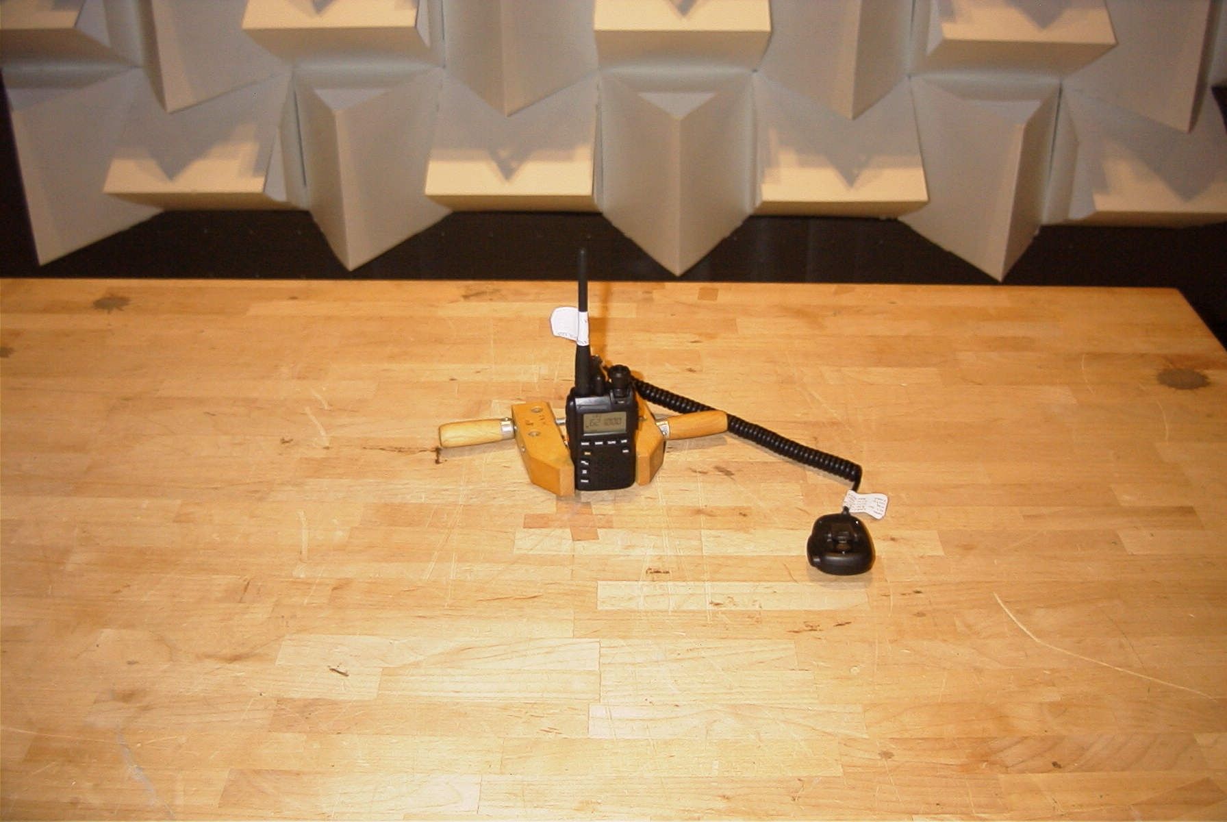
FCC PART 15 SCANNING RECEIVER Applicant VERTEX STANDARD CO., LTD. Address 4-8-8 NAKAMEGURO, MEGURO-KU TOKYO 153-8644 JAPAN FCC ID: K6620285X20 Model Number VX-3R Product Description AMATEUR RADIO RECEIVER Date Sample Received 5/1/2007 Date Tested 5/3/2007 Tested By JOSEPH SCOGLIO Approved By MARIO DE ARANZETA Report Number V\VERTEX\1020AUT7\1020AUT7TestReport.doc Test Results PASS FAIL THE ATTACHED REPORT SHALL NOT BE REPRODUCED EXCEPT IN FULL WITHOUT THE WRITTEN APPROVAL OF TIMCO ENGINEERING, INC. 849 NW State Road 45 Newberry, Fl 32669 USA Phone: 888.472.2424 or 352.472.5500 Fax: 352.472.2030 Email: [email protected] Website: www.timcoengr.com Certificate # 0955-01 APPLICANT: VERTEX STANDARD CO., LTD. FCC ID: K6620285X20 REPORT #: V\VERTEX\1020AUT7\1020AUT7TestReport.doc Page 2 of 10 TABLE OF CONTENTS STATEMENT OF COMPLIANCE.................................................................................. 3 GENERAL INFORMATION .......................................................................................... 4 TEST EQUIPMENT LIST............................................................................................. 5 TEST PROCEDURE ................................................................................................... 6 RADIATED SPURIOUS EMISSIONS............................................................................ 7 POWER LINE CONDUCTED INTERFERENCE............................................................. 9 38 Db REJECTION RADIO ....................................................................................... 10 APPLICANT: VERTEX STANDARD CO., LTD. FCC ID: K6620285X20 REPORT #: V\VERTEX\1020AUT7\1020AUT7TestReport.doc Page 3 of 10 STATEMENT OF COMPLIANCE This equipment has been tested in accordance with the standards identified in the referenced test report. To the best of my knowledge and belief, these tests were performed using the measurement procedures described in this report and demonstrate that the equipment complies with the appropriate standards. I attest that the necessary measurements were made by me or under my supervision, at TIMCO ENGINEERING, INC. located at 849 N.W. State Road 45, Newberry, Florida 32669 USA. Certificate #0955-01 Authorized by: Mario de Aranzeta Authorized Signature: < Mario de Aranzeta> Function: Engineer Date: 5/7/2007 APPLICANT: VERTEX STANDARD CO., LTD. FCC ID: K6620285X20 REPORT #: V\VERTEX\1020AUT7\1020AUT7TestReport.doc Page 4 of 10 GENERAL INFORMATION The test results relate only to the items tested. DUT Description AMATEUR RADIO RECEIVER FCC ID K6620285X20 Model Number VX-3R 110–120Vac/50– 60Hz DC Power DUT Power Source Battery Operated Exclusively Prototype Pre-Production Test Item Production Modifications to DUT None Test Standards FCC Part 15, Subpart B, ANSI C63.4-2003 APPLICANT: VERTEX STANDARD CO., LTD. FCC ID: K6620285X20 REPORT #: V\VERTEX\1020AUT7\1020AUT7TestReport.doc Page 5 of 10 TEST EQUIPMENT LIST Device Manufacturer Model Serial Number Cal/Char Date Due Date 3/10-Meter OATS TEI N/A N/A Listed 3/20/07 3/19/10 3-Meter OATS TEI N/A N/A Listed 1/11/06 1/10/09 Antenna: Biconnical Eaton 94455-1 1057 CAL 12/12/05 12/12/07 Antenna: Biconnical Eaton 94455-1 1096 CAL 10/11/06 10/11/08 Antenna: Biconnical Electro- Metrics BIA-25 1171 CAL 4/29/05 4/29/07 Analyzer Tan Tower Quasi-Peak Adapter HP 85650A 3303A01690 CAL 12/8/05 12/8/07 Analyzer Tan Tower RF Preselector HP 85685A 3221A01400 CAL 12/7/05 12/7/07 Analyzer Tan Tower Spectrum Analyzer HP 8568B Opt 462 3138A07786 3144A20661 CAL 12/7/05 12/7/07 LISN Electro- Metrics ANS-25/2 2604 CAL 10/5/06 10/5/08 LISN Electro- Metrics EM-7820 2682 CAL 4/28/05 4/28/07 Antenna: Log- Periodic Eaton 96005 1243 CAL 12/14/05 12/14/07 APPLICANT: VERTEX STANDARD CO., LTD. FCC ID: K6620285X20 REPORT #: V\VERTEX\1020AUT7\1020AUT7TestReport.doc Page 6 of 10 TEST PROCEDURE General: This report shall NOT be reproduced except in full without the written approval of TIMCO ENGINEERING, INC. Radiation Interference: The test procedure used was ANSI C63.4-2003 using a spectrum analyzer with a pre-selector. The bandwidth of the spectrum analyzer was 100 kHz with an appropriate sweep speed. The analyzer was calibrated in dB above a microvolt at the output of the antenna. The video bandwidth was always greater than or equal to the RBW. Formula Of Conversion Factors: The field strength at 3m was established by adding the meter reading of the spectrum analyzer (which is set to read in units of dBuV) to the antenna correction factor supplied by the antenna manufacturer. The antenna correction factors are stated in terms of dB. The gain of the preselector was accounted for in the spectrum analyzer meter reading. Example: Freq (MHz) Meter Reading + ACF +CL = FS 33 20 dBuV + 10.36 dB/m +0.40 dB =30.36 dBuV/m @ 3m ANSI C63.4-2003 Section 10.1.7 Measurement Procedures: The unit under test was placed on a table 80 cm high and with dimensions of 1mby 1.5m. The table used for radiated measurements is capable of continuous rotation. When an emission was found, the table was rotated to produce the maximum signal strength. At this point, the antenna was raised and lowered from 1m to 4m. The antenna was placed in both the horizontal and verticals planes. If powerline conducted testing was required for this device, the situation was similar for the conducted measurement except that the table did not rotate. The DUT was setup as described in ANSI C63.4-2003 with the DUT 40 cm from the vertical ground wall. APPLICANT: VERTEX STANDARD CO., LTD. FCC ID: K6620285X20 REPORT #: V\VERTEX\1020AUT7\1020AUT7TestReport.doc Page 7 of 10 RADIATED SPURIOUS EMISSIONS Rules Part No.: 15.109 Requirements: Frequency Limits 30 – 88 40.0 dBμV/m measured @ 3 meters 80 – 216 43.5 dBμV/m measured @ 3 meters 216 – 960 46.0 dBμV/m measured @ 3 meters Above 960 54.0 dBμV/m measured @ 3 meters Test Procedure: The procedure used was ANSI C63.4-2003. The frequency was scanned from 30 MHz to 1.0 GHz. When an emission was fo…
Text truncated - open the document above for the full version.
Contact Information
Applicant
Masatoshi Muraishi(Engineering Division)
Test Firm
Timco Engineering, Inc.Sid Sanders
Technical Specifications
| # | Rule Parts | Frequency Range | Power Output |
|---|---|---|---|
| 12 | 15B | 894 MHz - 960 MHz | - |
Other Applications from Yaesu Musen Co., Ltd.
K660E180X10
Dec 01, 2025BLUETOOTH MICROPHONE
Equipment Class
DTS - Digital Transmission System
K6630673Y3D
Aug 01, 2024VHF FM Marine Transceiver
Equipment Class
CXX - Communications Rcvr for use w/ licensed Tx and CBs
K6630653Y3D
Aug 01, 2024VHF FM Marine Transceiver
Equipment Class
CXX - Communications Rcvr for use w/ licensed Tx and CBs
K6630683X30
Jan 10, 2023VHF FM Marine Transceiver
Equipment Class
TNF - Licensed Non-Broadcast Transmitter Held to Face
K6650033X30
Nov 18, 2020Airband Radio Transceiver
Equipment Class
TNF - Licensed Non-Broadcast Transmitter Held to Face