K6620335X40AMATEUR RADIO WITH SCANNING RECEIVER
Yaesu Musen Co., Ltd.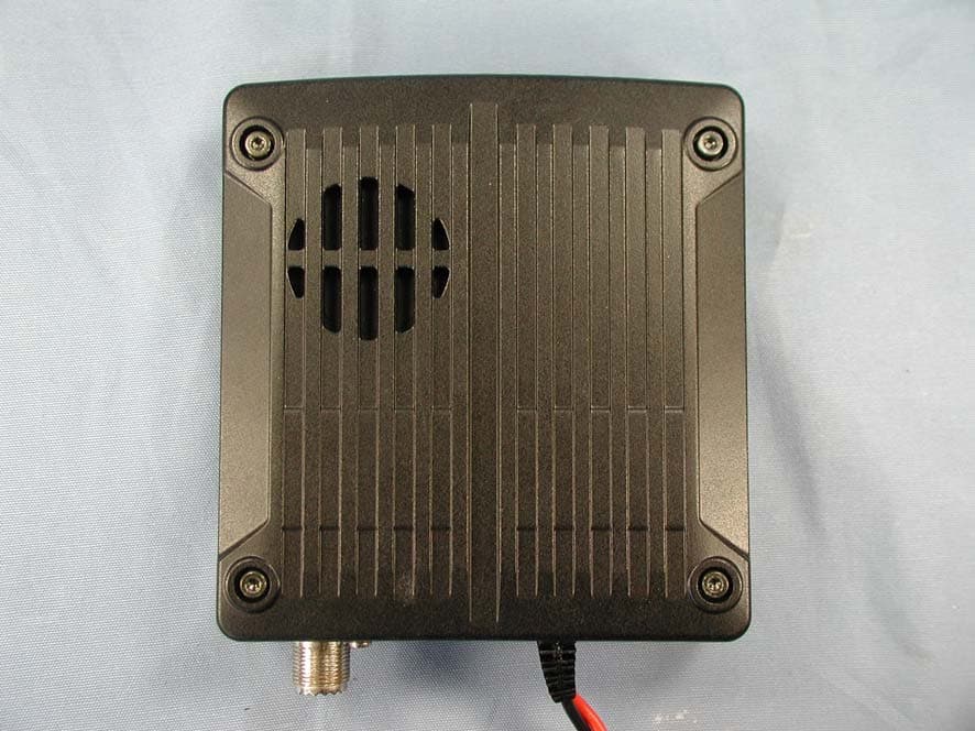
Click to zoom
Application Details
- Equipment Class
- CSR - Scanning Receiver
- Date of Grant
- Dec 16, 2009
- Application Purpose
- Original Equipment
- Date of Application
- Dec 16, 2009
- Equipment Note
- AMATEUR RADIO WITH SCANNING RECEIVER
- Frequency Range
- 800.00000000 - 999.99000000
- Company
- Yaesu Musen Co., Ltd.
- Country
- Japan
Documents & Files
Document Text
Text extracted from the exhibit documents filed with the FCC. Open a document above to read the original.
Users Manual
DUAL BAND FM TRANSCEIVER FTM-350R OPERATING MANUAL VERTEX STANDARD CO., LTD. 4-8-8 Nakameguro, Meguro-Ku, Tokyo 153-8644, Japan VERTEX STANDARD US Headquarters 10900 Walker Street, Cypress, CA 90630, U.S.A. YAESU UK LTD. Unit 12, Sun Valley Business Park, Winnall Close Winchester, Hampshire, SO23 0LB, U.K. VERTEX STANDARD HK LTD. Unit 5, 20/F., Seaview Centre, 139-141 Hoi Bun Road, Kwun Tong, Kowloon, Hong Kong VERTEX STANDARD ( AUSTRALIA ) PTY., LTD. Normanby Business Park, Unit 14/45 Normanby Road Notting Hill 3168, Victoria, Australia FCC ID: K6620335X40 IC: 511B-20335X40 Contents FCC ID: K6620335X40 IC: 511B-20335X40 FTM-350R O PERATING M ANUAL 1 F RONT P ANEL C ONTROLS & S WITCHES [ PTT ] K EY Press this key to transmit. [ SET ] ( S ET M ODE ) K EY Press this key to access the Set Mode. [ F ]( F UNCTION ) K EY Press this key to change the current functions of the[ SMART FUNCTION ] keys. [ DIAL ] K NOB Rotate this knob to select the operating frequency(or memory channel) of the right side receiver. Press and hold this knob for one second to enableto tuning the VFO frequency in 1 MHz step. When the right side receiver is set to “Main” band, press this knob briefly to activates the Band Scorpfeature. When the right side receiver is set to “Sub” band, press this knob briefly to change the right side receiver to “Main” band. [ SMART FUNCTION ] K EY These four keys select many of the most importantoperating features of the transceiver.When changing the operating function page or press-ing the [ FUNCTION ] key, the current function of these key will change and appear above each keys. [ DIAL ] K NOB Rotate this knob to select the operating frequency(or memory channel) of the left side receiver. Press and hold this knob for one second to enableto tuning the VFO frequency in 1 MHz step. When the left side receiver is set to “Main” band, press this knob briefly to activates the Band Scorpfeature. When the leftside receiver is set to “Sub” band, press this knob briefly to change the left side re- ceiver to “Main” band. M ICROPHONE [ B ]( B AND ) K EY Press this key to change the operating band of theMain band.Available bands are:Left Band : AM Radio, FM Radio, 144 MHz Band, 430 MHz Band, and Audio Line-In Right Band : 144 MHz Band and 430 MHz band You may assign the other function to this key. Seepage 36. [ VOL ] K NOB Adjusts the right side receiver’s audio volume. [ VOL ] K NOB Adjusts the left side receiver’s audio volume. [ POWER ] S WICTH Press and hold this key for two sec-onds to toggle the transceiver’spower on and off. Press this key briefly while thetransceiver is turned on to toggle thekey lockout feature on or off. [ FWD ] / [ BCK ]( P AGE ) K EY Press these keys briefly to select the operating func-tion pages.The available pages are: “ Radio ” page, “ Timer ” page, “ Baro/Alti ” page, “ Navigation ” page Ú , and “ GPS Status ” page Ú . Ú : Requires optional “ FGPS-1 ” GPS Unit. Press and hold in these keys toggle the Dual Receivefeature “on” and “off”. FCC ID: K6620335X40 IC: 511B-20335X40 FTM-350R O PERATING M ANUAL 2 T IMER P AGE O PERATION 1 Press the [ FWD ] or [ BCK ] key repeatedly, until the “Timer Page” appears. 2 Press the [ MODE ] key repeatedly, until the “Clock” ap- pears. To return to the “Radio” page, press the [ FWD ] or [ BCK ] key repeatedly, until the “Radio” Page appears.The FTM-350 ’s clock is setup from the Set mode item “ I01 DATA&TIME ADJUST ” in the “ TIMER/CLOCK ” group. See page 39 for details. 2 1 Press the [ FWD ] or [ BCK ] key repeatedly, until the “Timer Page” appears. 2 Press the [ MODE ] key repeatedly, until the “Count Up” timer appears.The “Count Up” timer has two kinds: which is with Lapfunction and without Lap function. 3 Press the [ SETUP ] key to set the interval time of the timer beep: rotate the [ DIAL ] knob to select the interval time, then press the [ SETUP ] key. 4 Press the [ START ] key to initiate the “Count Up” timer. 5 Press the [ LAP ] key to save the lap time, if desired (up to four laps). 6 Press the [ STOP ] key to stop the “Count Up” timer. 7 Press and hold the [ START ] key for two seconds to reset the “Count Up” timer. To return to the “Radio” page, press the [ FWD ] or [ BCK ] key repeatedly, until the “Radio” Page appears. 2 46 3 5 1 Press the [ FWD ] or [ BCK ] key repeatedly, until the “Timer Page” appears. 2 Press the [ MODE ] key repeatedly, until the “Count Down” timer appears.The “Count Down” timer has two kinds: which is withLap function and without Lap function. 3 Press the [ SETUP ] key to set the setup time: rotate the [ DIAL ] knob to select the setup time, then press the [ SETUP ] key. 4 Press the [ START ] key to initiate the “Count Down” timer. 5 Press the [ LAP ] key to save the lap time, if desired (up to four laps). 6 Press the [ STOP ] key to stop the “Count Down” timer. 7 Press and hold the [ START ] key for two seconds to reset the “Count Down” timer. To return to the “Radio” page, press the [ FWD ] or [ BCK ] key repeatedly, until the “Radio” Page appears. 2 467 3 5 “ C LOCK ” “ C OUNT U P ” T IMER “ C OUNT D OWN ” T IMER 1 1 1 FCC ID: K6620335X40 IC: 511B-20335X40 FTM-350R OPERATING MANUAL3 RADIO PAGE BASIC OPERATION 1 Press and hold the [ POWER ] key for two seconds to turn the transceiver on. 2 Rotates the [ VOL ] knob to adjust the audio volume level. 3 Adjusts the squelch throshold level: rotates the [ DIAL ] knob after pressing the [ SQL ] key. 4 Press the [ DIAL ] knob briefly to set the “Main” band. 5 Press the [ B ] key to select the operating band of the “Main” band. 6 Rotate the [ DIAL ] knob to select the operating frequency. 7 Speak into the microphone in a normal voice level while pressing the [ PTT ] key. 8 Press and hold the [ POWER ] key for two seconds to turn the transceiver off. 31 8 24 6 BASIC OPERATION You can do the basic operation in numerical order of the illustration below. 62 7 MICROPHONE 5 FCC ID: K6620335X40 IC: 511B-20335X40 FTM-350R OPERATING MANUAL4 [ …
Text truncated - open the document above for the full version.
Users Manual
FTM-350R OPERATING MANUAL17 PROGRAMMABLE MEMORY SCAN ( PMS ) This feature allows you to scan on the sub-band limits. 1. Store the lower sub-band limits into the memory channel “P1L”. 2. Store the upper sub-band limits into the memory channel “P1U”. 3. Set the “Main” band to memory mode by pressing the [ V/M ] key on the “F-1” cat- egory, if necessary. 4. Recall the memory channel “P1L” or “P1U”. 5. Press the [ F ] key briefly to change the [ SMART FUNCTION ] key’s category to “F- 2”. 6. Press the [ SCAN ] key on the “F-2” category to initiate the scanner within the pro- grammed range. 7. Press the [ SCAN ] key again to stop the scanner. 8. Press the [ V/M ] key on the “F-1” category to change the memory mode, then press the [ V/M ] key again to change the VFO mode. 9. Nine pairs of band limit memories, labeled “P1L/P1U” through “P9L/P9U” available. You therefore can set lower and upper operation limits on a number of bands, if you like. You may customize the functions of the Memory Scan via Set Mode items “D03 MEMORY SCAN TYEP” in the “MEMORY” group, “F04 MEMORY SKIP/SELCT”, “F03 SCAN RESUME”, “F04 SCAN STOP BEEP” in the “SCAN” group, and “G08 RX COVER- AGE” in the “SYSTEM” group. PRIORITY CHANNEL SCAN ( DUAL WATCH ) This feature is a two-channel scanning capability which allows you to operate on a VFO or Memory channel, while periodically checking a “Priority” memory channel “000” for ac- tivity. 1. Store the frequency which you wish to check periodic into the “Priority” memory channel “PRM”. 2. Press the [ F ] key repeatedly until the [ SMART FUNCTION ] key’s category replaces to “F-2”. 3. Press the [ DW ] key on the “F-2” category to initiate the Dual Watch feature. 4. Press the [ SCAN ] key again to stop the Dual Watch feature. You may customize the functions of the Dual Watch feature via Set Mode items “F01 DUAL WATCH STOP” and “F03 SCAN RESUME” in the “SCAN” group. SCAN OPERATION FCC ID: K6620335X40 IC: 511B-20335X40 FTM-350R OPERATING MANUAL18 BLUETOOTH ® OPERATION When install the optional BU-1 Bluetooth ® Unit, the FTM-350R to send/receive voice message with the optional BH-1A or BH-2A Bluetooth ® Headset via wireless links. PAIRING 1. Turn the radio and Bluetooth ® Headset both off. 2. Turn the radio on while press and holding the key which is located at the left of the [ POWER ] switch to enter the “Special Function” mode. 3. Rotate the left side [ DIAL ] knob to select the function menu item “9 B-T PAIRING”. 4. Press the left side [ DIAL ] knob. 5. Press and hold the power switch on the Bluetooth ® Headset for five seconds, until the Bluetooth ® Headset’s indicator blinks red/blue alternately. 6. Press the left side [ DIAL ] knob to initiate the pairing. 7. If the pairing is successful (requires a 20 to 30 seconds), “PAIRING OK !” notation will appear on the display. The FTM-350R will turn off and back on again. When the Bluetooth ® Headset is correctly recognized by the FTM-350, the Bluetooth ® Headset’s indicator will blink blue. 8. Set up the various function of the Bluetooth ® via Set Mode items “K01 BLUETOOTH”. FCC ID: K6620335X40 IC: 511B-20335X40 FTM-350R OPERATING MANUAL19 BLUETOOTH ® OPERATION OPERATION 1. When the Bluetooth ® Headset is correctly recognized by the FTM-350R, “” icon will appear on the display of the FTM-350R and the LED indicator of the Bluetooth ® Headset will blink blue. 2. Adjust the receiver audio level using the [ VOLUME ( + )] / [ VOLUME ( – )] switches on the Bluetooth ® Headset. 3. Press the PTT switch on the Bluetooth ® Headset to transmit. Release the PTT switch to return to receive. 4. If your Bluetooth ® Headset is BH-2A, you may adjust the microphone gain (Five steps) of the BH-2A by pressing the [ VOLUME ( + )] / [ VOLUME ( – )] switch while press- ing and holding the PTT switch, if desired. 5. The communication range between the Bluetooth ® Headset and FTM-350 is around 1 m (3 ft). If you move out of range, a beep will be heard from the Bluetooth ® Head- set to alert you. If you move back into range, the Bluetooth ® Headset will beep to alert you that you are back within range. 6. When the battery voltage of the Bluetooth ® Headset is low; a.the LED on the Bluetooth ® Headset will blink Red and Blue. b. a beep will be heard from the Bluetooth ® Headset. c.the “ ” icon on the FTM-350R will be blinking fast. Charge the battery of the Bluetooth ® Headset. In the factory default, the FTM-350R’s internal and external speakers are disabled when the Bluetooth ® Headset is correctly recognized. Additionally, the microphones which lo- cated on the front panel and connected to the front panel MIC jack are also disabled when the Bluetooth ® Headset is correctly recognized. However, the microphone which con- nected to the transceiver’s MIC jack is alive. You may customize the Bluetooth ® operation via Set Mode items “K01 BLUETOOTH” in the “OPTION” group. See page 42. FCC ID: K6620335X40 IC: 511B-20335X40 FTM-350R OPERATING MANUAL20 INTERNET CONNECTION FEATURE The FTM-350R can be used to access a “node” (repeater or base station) which is tied into the Vertex Standard WiRES™ (Wide-Coverage Internet Repeater Enhancement System) network, operating in the “SRG” (Sister Radio Group) mode. Details may be found at the WiRES-II Web site: http://www.vxstd.com/en/wiresinfo-en/. SRG ( “SISTER RADIO GROUP” ) MODE 1. Sets the Set Mode item “J06 WiRES” in the “SIGNALING” group to “SRG”. See page 41. 2. Selects the access number corresponding to the WiRES™ repeater via Set Mode item “J07 WiRES MEMORY” in the “SIGNALING” group. See page 41. 3. When exit from the Set Mode, activate the Internet Connection feature in the “SRG” mode. 4. With the Internet Connection feature activated, the FTM-350R will generate a brief (0.1 sec) DTMF tone according to your selection in step 2. This DTMF tone is sent at the beginning of every transmission to establish or maintain the link to the remote WIRES™ repeater operating in the “SRG” mode. 4. To disable the Internet Connection …
Text truncated - open the document above for the full version.
Users Manual
FTM-350R OPERATING MANUAL39 TIMER/CLOCK GROUP I01: DATA&TIME ADJUST Function: Sets the clock time. 1. Press the left side [ DIAL ] knob to enable adjust this item. 2. Enter the your local time by the 24-hour system. Use the [ ] / [ ] key to navigate to each column, then rotate the left side [ DIAL ] knob to select desired numbers in each column. 3. Press the left side [ DIAL ] knob again to save the new setting. I02: DATA&TIME FORMAT Function: Available Values: DATE: yyyy/mm/dd, yyyy/dd/mm, mm/dd/yyyy, or dd/mm/yyyy TIME: 12 hour or 24hour Default: DATE: dd/mm/yyyy, TIME: 24hour I03: TIME SIGNAL Function: Enables/Disables the Timer Signal “on and “off”. Available Values: OFF or ON Default: OFF I04: TIME ZONE Function: Sets thetime offset between the local time and UTC. Available Values: UTC-13:00 ~ UTC+13:00 (0.5H/step) Default: UTC±0:00 LONDON MISCELLANEOUS SETTING ( SET MODE OPERATION ) FCC ID: K6620335X40 IC: 511B-20335X40 FTM-350R OPERATING MANUAL40 SIGNALING GROUP J01: BELL RINGER Function: Enables/Disables the Bell ringer function and select its ringer repetitions. Available Values: OFF, 1 time, 3 times, 5 times, 8 times, or CONTINUOUS Default: OFF When this item is enabled, the FTM-350R ring a “bell” sound when you are called by a station whose thansceiver is sending a CTCSS tone, DCS code or CTCSS tone pair which matches that set into your decoder. J02: DTMF MEMORY Function: Programs the DTMF string for use the DTMF autodialer and FRG command of the WiRES. Available memories are nine memories. 1. Rotate the left side [ DIAL ] knob to select the DTMF memory register (1 - 9) into which you wish to store. 2. Press the left side [ DIAL ] knob briefly. 3. Rotate the left side [ DIAL ] knob, or press one of the microphone’s keypad, to select the first digit of the DTMF string. 4. When selects the first digit of the DTMF string by the left side DIAL knob, press the [ ] key to move to the next digit. 5. Repeats steps 3 and 4 to program the remaining DTMF string. 6. You may back the cursor by pressing the [ ] key. 7. Press the [ CLR ] key to clear the previous stored data, if desired. 8. Press the [ ENT ] key to save the setting. J03: DTMF MODE Function: Enables/Disables the DTMF autodialer feature. Available Values: OFF or ON Default: OFF When this item is set to “ON”, you may send a J04: PAGER CODE Function: Sets the Pager Code for the Enhanced CTCSS Paging & Code Squelch. Available Values: Default: MISCELLANEOUS SETTING ( SET MODE OPERATION ) FCC ID: K6620335X40 IC: 511B-20335X40 FTM-350R OPERATING MANUAL41 SIGNALING GROUP J05: SQL EXPANSION Function: Enables/Disables the split CTCSS/DCS coding. Available Values: OFF or ON Default: OFF When this item is set to “ON”, you chan see the following additional parameters after “PAGER” parameters while selecting the squelch type selection by pressing the [ TYPE ] key on the SQL categoly. DCS ENC:DCS Encoder only. “DC” icon will appear while operating. TONE DCS: Encodes a CTCSS tone and decodes a DCS code. “T-D” icon will appear while operating. DCS TSQL: Encodes a DCS code and decodes a CTCSS tone. “D-T” icon will appear while operating. J06: WiRES Function: Enables/Disables the Internet Connection feature (WiRES TM ) and its operating mode selection. Available Values: OFF, FRG, or SRG Default: OFF J07: WiRES MEMORY Function: Selects the access number (DTMF digit) for the SRG operation of the Internet Connection feature (WiRES TM ). Available Values: CODE 0 ~ CODE 9, CODE A ~ CODE D, CODE ¼, or CODE # Default: CODE 1 MISCELLANEOUS SETTING ( SET MODE OPERATION ) FCC ID: K6620335X40 IC: 511B-20335X40 FTM-350R OPERATING MANUAL42 K01 BLUETOOTH Function: Sets up the optional BU-1 Bluetooth ® Unit. Available Values: 1 AUDIO: MANUAL or AUTO 2 MODE: MONAURAL or STEREO 3 SAVE:OFF or ON 4 VOX:OFF, PTT, VOX HIGH, or VOX LOW Default: 1 AUDIO: AUTO, 2 MODE: MONAURAL, 3 SAVE: ON, 4 VOX: PTT AUDIO MANUAL:The FTM-350R’s internal/external speaker function obays setting of the Set Mode item “A03 SPEAKER” in the “AUDIO” group evenif the the Bluetooth ® Headset is correctly recognized AUDIO AUTO:When the Bluetooth ® Headset is correctly recognized, the FTM- 350R’s internal and external speakers are disabled. MODE MONAURAL: Outputs monaural receive audio while listening to the FM Broad- cast band, if you use the BH-2A Bluetooth ® Headset. MODE STEREO:Outputs stereo receive audio while listening to the FM Broadcast band. Note: When this mode is selected, the VOX function does not work even if the VOX function is selected in item 4 above, if you use the BH-2A Bluetooth ® Headset. The TX/RX switching is performed by pressing the PTT switch. SAVE OFF:Disable the Battery Saver in the Bluetooth ® Headset. SAVE ON:Activates the Battery Saver in the Bluetooth ® Headset. VOX OFF:Disable the TX/RX switching circuit of the Bluetooth ® Headset. VOX PTT:Activates the Bluetooth ® Headset for use with the PTT circuit. VOX VOX HIGH:Activates the Bluetooth ® Headset with the VOX feature (VOX Gain: High). VOX VOX LOW:Activates the Bluetooth ® Headset with the VOX feature (VOX Gain: Low). OPTION GROUP MISCELLANEOUS SETTING ( SET MODE OPERATION ) FCC ID: K6620335X40 IC: 511B-20335X40 FTM-350R OPERATING MANUAL43 K02 FRP-1 Function: Sets up the optional FPR-1 Monitor Unit. Available Values: 1 BATT SAVE: OFF, MIN, MID, or MAX 2 SQL LEVEL: OFF, MIN, 2 ~ 7, or MAX Default: 1 BATT SAVE: MIN, 2 SQL LEVEL: 2 K03 VOICE Function: Sets up the optional FVS-2 Voice Guide Unit. Available Values: 1 PLAY/REC: FREE 5min or LAST 30sec 2 ANNOUNCE: OFF, MENUAL, or AUTO 3 LANGUAGE: JAPANESE or ENGLISH 3 VOLUME: LOW, MID, or HIGH Default: 1 PLAY/REC: FREE 5min, 2 ANNOUNCE: AUTO, 3 VOLUME: MID OPTION GROUP MISCELLANEOUS SETTING ( SET MODE OPERATION ) FCC ID: K6620335X40 IC: 511B-20335X40 FTM-350R OPERATING MANUAL44 SPECIAL FUNCTION MENU Static electricity may occasionally cause erratic or unpredictable operation of the micropro- cessor. If this happens, resetting of the microprocessor may restore n…
Text truncated - open the document above for the full version.
Attestation Statements
November 10, 2009 Federal Communications Commission Authorization and Evaluation Division, 7435 Oakland Mills Road Columbia, MD 21046 USA Re: FTM-350R (FCC ID: K6620335X40) Gentlemen: A. Part 15.21 Compliance Statement Drawing: B. Part 15.21 Compliance Statement Drawing Location: IN OPERATION MANUAL (location on inside back cover) Sincerely, Vertex Standard Co., Ltd. Yukimasa Tomita Executive Managing Officer Engineering Division Part 15.21: Changes or modifications to this device not expressly approved by Vertex Standard could void the user’s authorization to operate this device. 20mm 97mm
Cover Letter(s)
November 10, 2009 Federal Communications Commission EQUIPMENT APPROVAL SERVICES P. O. Box 358315 Pittsburgh, PA 15251-5315 Attention: Authorization and Evaluation Division Reference: FTM-350R (FCC ID: K6620335X40) Pursuant to Sections 0.457 (d)(1)(ii) and 0.459 of the Commission’s Rules, the Applicant hereby requires confidential treatment of some of the information accompanying this Application, as listed below: ・ Block Diagram ・ Schematics These materials contain trade secrets and proprietary information not customarily released to the public. The public disclosure of these matters might be harmful to the Applicant and provide unjustified benefits to its competitors. The Applicant understands that pursuant to Rule 0.457 (d)(1)(ii), disclosure of the Application and all accompanying documentation will not be made before the date of Grant for this Application. Sincerely, Vertex Standard Co., Ltd. Yukimasa Tomita Executive Managing Officer Engineering Division
Cover Letter(s)
November 10, 2009 Federal Communications Commission Authorization and Evaluation Division, 7435 Oakland Mills Road Columbia, MD 21046 USA Re: FTM-350R (FCC ID: K6620335X40) Gentlemen: Part 15.19 Compliance Statement is placed on the Bottom of case. Sincerely, Vertex Standard Co., Ltd. Yukimasa Tomita Executive Managing Officer Engineering Division
Cover Letter(s)
November 10, 2009 Federal Communications Commission Authorization and Evaluation Division, 7435 Oakland Mills Road Columbia, MD 21046 USA Re: FTM-350R (FCC ID: K6620335X40) Gentlemen: The scanner receiver equipment meets the requirements of the FCC Rules, 15.121(a). Compliance is achieved through the following methods: The scanner receiver in this equipment is incapable of tuning, or readily being altered, by the User to operate within the frequency bands allocated to the Domestic Public Cellular Telecommunications Service in Part 22. Blocking of the cellular frequencies is implemented in the firmware of the unit’s main control central processing unit (CPU). Coverage of 824 – 849 MHz and 869 – 894 MHz is completely blocked, since it is done in the microprocessor, and cannot be re-enabled by any user-accessible procedure, including diode, resistor, or jumper changes, nor by connection of any external device such as a personal computer, nor by installation of any “special” enabling semiconductor device. Sincerely, Vertex Standard Co., Ltd. Yukimasa Tomita Executive Managing Officer Engineering Division
External Photos
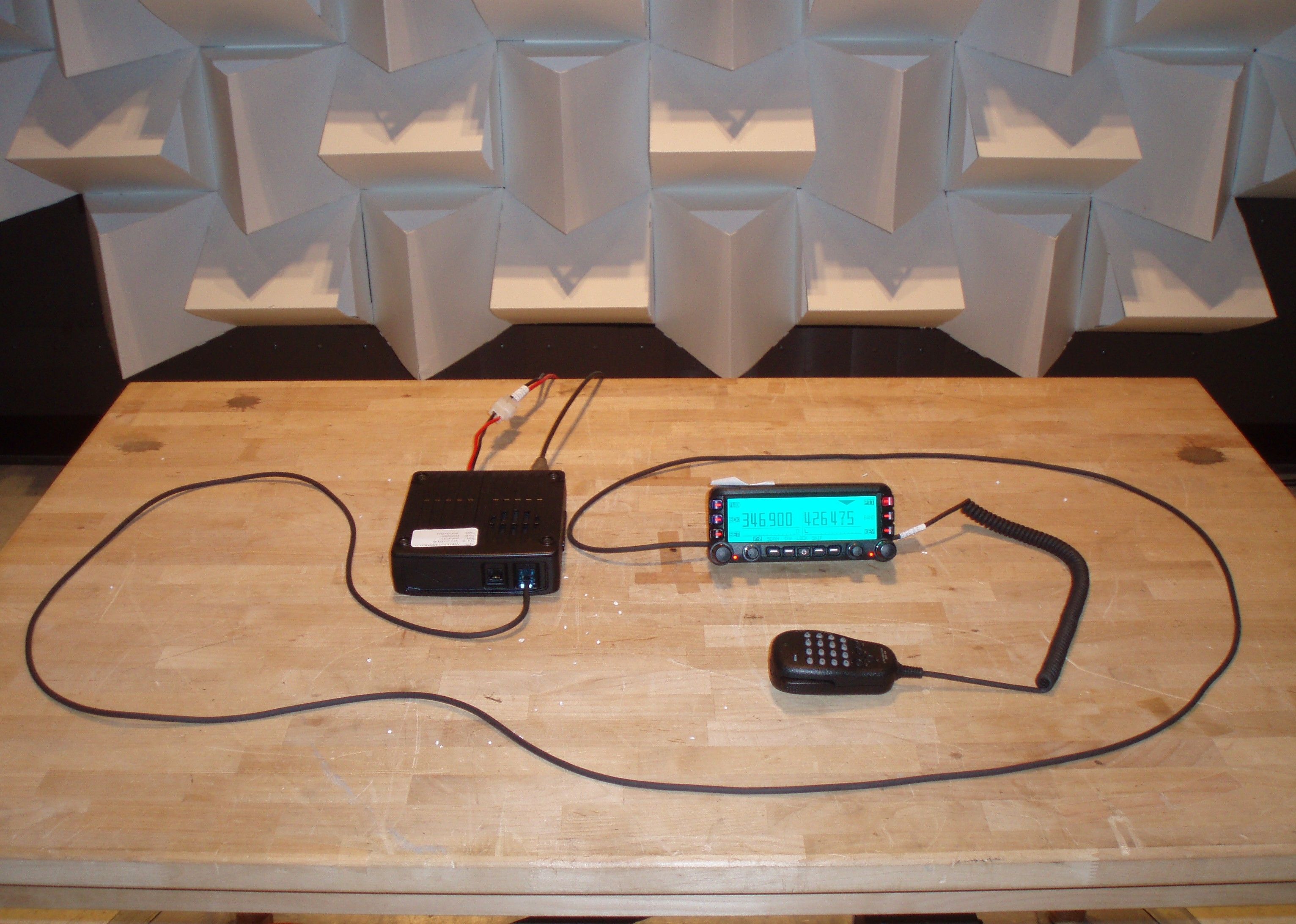
FCC ID:K6620335X40 IC ID:511B-20335X40 Vertex Standard Co., Ltd. Controller and main-body Front view of controller FCC ID:K6620335X40 IC ID:511B-20335X40 Vertex Standard Co., Ltd. Rear view of controller Top view of controller FCC ID:K6620335X40 IC ID:511B-20335X40 Vertex Standard Co., Ltd. Bottom view of controller Left side view of controller FCC ID:K6620335X40 IC ID:511B-20335X40 Vertex Standard Co., Ltd. Right side view of controller Front view of main-body FCC ID:K6620335X40 IC ID:511B-20335X40 Vertex Standard Co., Ltd. Rear view of main-body Top view of main-body FCC ID:K6620335X40 IC ID:511B-20335X40 Vertex Standard Co., Ltd. Bottom view of main-body Right side view of main-body FCC ID:K6620335X40 IC ID:511B-20335X40 Vertex Standard Co., Ltd. Left side view of main-body Microphone FCC ID:K6620335X40 IC ID:511B-20335X40 Vertex Standard Co., Ltd. DC Cable
ID Label/Location Info
FTM-350RFTM-350R LABEL DRAWINGLABEL DRAWING Vertex Standard Co., Ltd.Vertex Standard Co., Ltd. ID / Part 15.19 and CAUTION drawings ID drawing Part 15.19 and CAUTION drawings Label location FTM-350R VERTEX STANDARD CO., LTD. MADE IN JAPAN IC: 511B-20335X40 FCC ID: K6620335X40 4909959000000 SER NO. 00000000 (1:2)
Parts List/Tune Up Info
FCC ID: K6620335X40 IC: 511B-20335X40 Alignment Vertex Standard Co., Ltd. 1 FTM-350R Alignment Introduction and Precautions The FTM-350R has been carefully aligned at the factory for the specified performance across the 144 MHz and 430 MHz amateur bands. Realignment should therefore not be necessary except in the event of a component failure. All component replacement and service should be performed only by an authorized Yaesu representative, or the warranty policy may be voided. The following procedures cover the sometimes critical and tedious adjustments that are not normally required once the transceiver has left the factory. However, if damage occurs and some parts are replaced, realignment may be required. If a sudden problem occurs during normal operation, it is likely due to component failure; realignment should not be done until after the faulty component has been replaced. We recommend that servicing be performed only by authorized Yaesu service technicians who are experienced with the circuitry and fully equipped for repair and alignment. Therefore, if a fault is suspected, contact the dealer from whom the transceiver was purchased for instructions regarding repair. Authorized Yaesu service technicians realign all circuits and make complete performance checks to ensure compliance with factory specifications after replacing any faulty components. Those who do undertake any of the following alignments are cautioned to proceed at their own risk. Problems caused by unauthorized attempts at realignment are not covered by the warranty policy. Also, Yaesu must reserve the right to change circuits and alignment procedures in the interest of improved performance, without notifying owners. Under no circumstances should any alignment be attempted unless the normal function and operation of the transceiver are clearly understood, the cause of the malfunction has been clearly pinpointed and any faulty components replaced, and the need for realignment determined to be absolutely necessary. FCC ID: K6620335X40 IC: 511B-20335X40 Alignment Vertex Standard Co., Ltd. 2 Required Test Equipment The following test equipment (and thorough familiarity with its correct use) is necessary for complete realignment. Correction of problems caused by misalignment resulting from use of improper test equipment is not covered under the warranty policy. While most steps do not require all of the equipment listed, the interactions of some adjustments may require that more complex adjustments be performed afterwards. Do not attempt to perform only a single step unless it is clearly isolated electrically from all other steps. Have all test equipment ready before beginning, and follow all of the steps in a section in the order presented. Regulated DC Power Supply: adjustable from 10 to 17 VDC, 20 A RF Signal Generator with calibrated output level at 500 MHz Frequency Counter: ±0.1 ppm accuracy at 500 MHz AF Signal Generator SINAD Meter Oscilloscope Spectrum Analyzer Deviation Meter (linear detector) AF Milivoltmetr AF Dummy Load: 4 Ω, 5 W DC Voltmeter: high impedance Inline Wattmeter with 5% accuracy at 500 MHz 50-Ohm non-reactive Dummy Load: 100 watts at 500 MHz VHF/UHF Sampling Coupler Alignment Preparation & Precautions A dummy load and inline wattmeter must be connected to the main antenna jack in all procedures that call for transmission, except where specified otherwise. Correct alignment is not possible with an antenna. After completing one step, read the following step to determine whether the same test equipment will be required. If not, remove the test equipment (except dummy load and wattmeter, if connected) before proceeding. Correct alignment requires that the ambient temperature in the repair shop be the same as that of the transceiver and test equipment, and that this temperature be held constant between 20 °C and 30 °C (68 °C to 86 °F). When the transceiver is brought into the shop from hot or cold air it should be allowed some time for thermal equalization with the environment before alignment. If possible, alignments should be made with oscillator FCC ID: K6620335X40 IC: 511B-20335X40 Alignment Vertex Standard Co., Ltd. 3 shields and circuit boards firmly affixed in place. Also, the test equipment must be thoroughly warmed up before beginning. Notes: Signal levels in dB referred to in alignment are based on 0 dBμ = 0.5 μV. All items tune and/or adjust by Auto-Tuning Mode or Manual Tuning Mode. Transmitter Deviation With the wattmeter, dummy load and deviation meter connected to the antenna jack. Inject a 1 kHz audio signal as a level of 50 mV to the microphone-input port. Key the transmitter on 146.05 (and 440.05) MHz. Adjust the frequency deviation is within 4.0 - 4.4 kHz on the deviation meter. CTCSS Deviation With the wattmeter, dummy load and deviation meter connected to the antenna jack. Key the transmitter on 146.05 (and 440.05) MHz. Adjust the frequency deviation is within 0.65-0.75 kHz on the deviation meter. DCS Deviation With the wattmeter, dummy load and deviation meter connected to the antenna jack. Key the transmitter on 146.05 (and 440.05) MHz. Adjust the frequency deviation is within 0.65-0.75 kHz on the deviation meter. FCC ID: K6620335X40 IC: 511B-20335X40 Alignment Vertex Standard Co., Ltd. 4 Transmitter Power With the power meter, dummy load and deviation meter connected to the antenna jack. Key the transmitter on 146.05 MHz. Adjust the output power is within 50 ±0.5 W on the power meter. (HI) Key the transmitter on 146.05 MHz. Adjust the output power is within 20 ±0.5 W on the power meter. (MID) Key the transmitter on 146.05 MHz. Adjust the output power is within 5 ±0.5 W on the power meter. (LOW) Key the transmitter on 440.05 MHz. Adjust the output power is within 50 ±0.5 W on the power meter. (HI) Key the transmitter on 440.05 MHz. Adjust the output power is within 20 ±0.5 W on the power meter. (MID) Key the transmitter o…
Text truncated - open the document above for the full version.
Parts List/Tune Up Info
1 FCC ID: K6620335X40 / IC: 511B-20335X40 FTM-350RSemi-Conductor Parts List Address Parts Code Device NameDescriptionTYP VAL MAIN-UNIT D 1001 G2070676 DiodeHVC131TRF-E D 1002 G2070584 DiodeHSC277TRF-E D 1003 G2070596 DiodeHVC350B-TRF-E D 1004 G2070596 DiodeHVC350B-TRF-E D 1005 G2070596 DiodeHVC350B-TRF-E D 1006 G2070584 DiodeHSC277TRF-E D 1007 G2070676 DiodeHVC131TRF-E D 1008 G2070676 DiodeHVC131TRF-E D 1009 G2070676 DiodeHVC131TRF-E D 1010 G2070584 DiodeHSC277TRF-E D 1011 G2070596 DiodeHVC350B-TRF-E D 1012 G2070596 DiodeHVC350B-TRF-E D 1013 G2070596 DiodeHVC350B-TRF-E D 1014 G2070676 DiodeHVC131TRF-E D 1015 G2070676 DiodeHVC131TRF-E D 1016 G2070676 DiodeHVC131TRF-E D 1017 G2070902 DiodeHVC365 TRF-E D 1018 G2070902 DiodeHVC365 TRF-E D 1019 G2070902 DiodeHVC365 TRF-E D 1020 G2070676 DiodeHVC131TRF-E D 1021 G2070902 DiodeHVC365 TRF-E D 1022 G2070902 DiodeHVC365 TRF-E D 1023 G2070902 DiodeHVC365 TRF-E D 1024 G2070676 DiodeHVC131TRF-E D 1025 G2070676 DiodeHVC131TRF-E D 1026 G2070676 DiodeHVC131TRF-E D 1027 G2070676 DiodeHVC131TRF-E D 1028 G2070174 DiodeDAN222 TL D 1029 G2070588 DiodeHVC355B TRF-E D 1030 G2070588 DiodeHVC355B TRF-E D 1031 G2070676 DiodeHVC131TRF-E D 1032 G2070588 DiodeHVC355B TRF-E D 1033 G2070588 DiodeHVC355B TRF-E D 1034 G2070676 DiodeHVC131TRF-E D 1035 G2070588 DiodeHVC355B TRF-E D 1036 G2070588 DiodeHVC355B TRF-E D 1201 Q9000827 Surge Absorber RHCA-301Q43U D 1202 G2070128 DiodeRLS135 TE-11 D 1203 G2070128 DiodeRLS135 TE-11 D 1204 G2071124 DiodeL709CER D 1205 G2071124 DiodeL709CER D 1206 G2070858 DiodeMA2S72800L D 1207 G2070858 DiodeMA2S72800L D 1208 G2070908 Zener DiodeUDZS TE-17 5.1B D 1209 G2070634 Diode1SS400 TE61 D 1210 G2070584 DiodeHSC277TRF-E D 1211 G2070676 DiodeHVC131TRF-E D 1212 G2070634 Diode1SS400 TE61 D 1213 G2070676 Dio…
Text truncated - open the document above for the full version.
Contact Information
Applicant
Masatoshi Muraishi(Engineering Division)
Test Firm
Timco Engineering, Inc.Bruno Clavier
Technical Specifications
| # | Rule Parts | Frequency Range | Power Output |
|---|---|---|---|
| 13 | 15B | 800 MHz - 999.99 MHz | - |
Other Applications from Yaesu Musen Co., Ltd.
K660E180X10
Dec 01, 2025BLUETOOTH MICROPHONE
Equipment Class
DTS - Digital Transmission System
K6630673Y3D
Aug 01, 2024VHF FM Marine Transceiver
Equipment Class
CXX - Communications Rcvr for use w/ licensed Tx and CBs
K6630653Y3D
Aug 01, 2024VHF FM Marine Transceiver
Equipment Class
CXX - Communications Rcvr for use w/ licensed Tx and CBs
K6630683X30
Jan 10, 2023VHF FM Marine Transceiver
Equipment Class
TNF - Licensed Non-Broadcast Transmitter Held to Face
K6650033X30
Nov 18, 2020Airband Radio Transceiver
Equipment Class
TNF - Licensed Non-Broadcast Transmitter Held to Face