K6620415X20AMATEUR RADIO WITH SCANNING RECEIVER
Yaesu Musen Co., Ltd.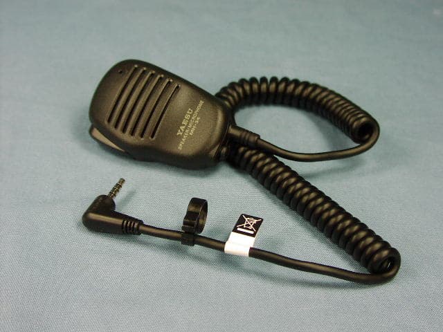
Click to zoom
Application Details
- Equipment Class
- CSR - Scanning Receiver
- Date of Grant
- Apr 01, 2010
- Application Purpose
- Original Equipment
- Date of Application
- Apr 01, 2010
- Equipment Note
- AMATEUR RADIO WITH SCANNING RECEIVER
- Frequency Range
- 800.00000000 - 999.00000000
- Company
- Yaesu Musen Co., Ltd.
- Country
- Japan
Documents & Files
Document Text
Text extracted from the exhibit documents filed with the FCC. Open a document above to read the original.
Attestation Statements
March 09, 2010 Federal Communications Commission Authorization and Evaluation Division, 7435 Oakland Mills Road Columbia, MD 21046 USA Re: VX-8GR (FCC ID: K6620415X20) Gentlemen: The scanner receiver equipment meets the requirements of the FCC Rules, 15.121(a). Compliance is achieved through the following methods: The scanner receiver in this equipment is incapable of tuning, or readily being altered, by the User to operate within the frequency bands allocated to the Domestic Public Cellular Telecommunications Service in Part 22. Blocking of the cellular frequencies is implemented in the firmware of the unit’s main control central processing unit (CPU). Coverage of 824 – 849 MHz and 869 – 894 MHz is completely blocked, since it is done in the microprocessor, and cannot be re-enabled by any user-accessible procedure, including diode, resistor, or jumper changes, nor by connection of any external device such as a personal computer, nor by installation of any “special” enabling semiconductor device. Sincerely, Vertex Standard Co., Ltd. Yukimasa Tomita Executive Managing Officer Engineering Division
External Photos
FCC IC: K6620415X20 / IC: 511B-20415X20 Vertex Standard Co., Ltd. Front view with Antenna Front view without Antenna FCC IC: K6620415X20 / IC: 511B-20415X20 Vertex Standard Co., Ltd. Rear view with Battery Pack and Antenna Rear view without Battery Pack FCC IC: K6620415X20 / IC: 511B-20415X20 Vertex Standard Co., Ltd. Right side view Left side view FCC IC: K6620415X20 / IC: 511B-20415X20 Vertex Standard Co., Ltd. Top view Bottom view FCC IC: K6620415X20 / IC: 511B-20415X20 Vertex Standard Co., Ltd. Battery Pack with Belt Clip Battery Pack FCC IC: K6620415X20 / IC: 511B-20415X20 Vertex Standard Co., Ltd. View of Battery Charger View of Battery Charger FCC IC: K6620415X20 / IC: 511B-20415X20 Vertex Standard Co., Ltd. Microphone Antenna
ID Label/Location Info
VX-8GRVX-8GR LABEL DRAWINGLABEL DRAWING Vertex Standard Co., Ltd.Vertex Standard Co., Ltd. ID Label drawing VX-8GR K6620415X20 511B-20415X20 Label location CAUTION Label drawing 2:1 2:1
Parts List/Tune Up Info
FCC ID: K6620415X20 IC: 511B-20415X20 VX-8GR Alignment Vertex Standard Co.,Ltd. 1 VX-8GR Alignment Introduction The VX-8GR is carefully aligned at the factory for the specified performance across the amateur band. Realignment should therefore not be necessary except in the event of a component failure. Only an authorized Yaesu representative should perform all component replacement and service, or the warranty policy may be void. The following procedures cover the adjustments that are not normally required once the transceiver has left the factory. However, if damage occurs and some parts subsequently are replaced, realignment may be required. If a sudden problem occurs during normal operation, it is likely due to component failure; realignment should not be done until after the faulty component has been replaced. We recommend that servicing be performed only by authorized Yaesu service technicians who are experienced with the circuitry and fully equipped for repair and alignment. If a fault is suspected, contact the dealer from whom the transceiver was purchased for instructions regarding repair. Authorized Yaesu service technicians realign all circuits and make complete performance checks to ensure compliance with factory specifications after replacing any faulty components. Those who do undertake any of the following alignments are cautioned to proceed at their own risk. Problems caused by unauthorized attempts at realignment are not covered by the warranty policy. Also, Yaesu reserves the right to change circuits and alignment procedures in the interest of improved performance, without notifying owners. Under no circumstances should any alignment be attempted unless the normal function and operation of the transceiver are clearly understood, the cause of the malfunction has been clearly pinpointed and any faulty components replaced, and realignment determined to be absolutely necessary. The following test equipment (and familiarity with its use) is necessary for complete realignment. Correction of problems caused by misalignment resulting from use of improper test equipment is not covered under the warranty policy. While most steps do not require all of the equipment listed, the interactions of some adjustments may require that more complex adjustments be performed afterwards. Do not attempt to perform only a single step unless it is clearly isolated electrically from all other steps. Have all test equipment ready before beginning and, follow all of the steps in a section in the order presented. Required Test Equipment • RF Signal Generator with calibrated output level at 1 GHz • Deviation Meter (linear detector) FCC ID: K6620415X20 IC: 511B-20415X20 VX-8GR Alignment Vertex Standard Co.,Ltd. 2 • In-line Wattmeter with 5% accuracy at 500 MHz • 50-ohm, 10-W RF Dummy Load • 8-ohm AF Dummy Load • Regulated DC Power Supply adjustable from 3 to 15 V DC, 3A • Frequency Counter: 0.2-ppm accuracy at 1 GHz • AF Signal Generator • AC Voltmeter • DC Voltmeter: high impedance • UHF Sampling Coupler • SINAD Meter Alignment Preparation & Precautions A 10-W RF load and in-line wattmeter must be connected to the main antenna jack in all procedures that call for transmission, alignment is not possible with an antenna. After completing one step, read the next step to see if the same test equipment is required. If not, remove the test equipment (except dummy load and wattmeter, if connected) before proceeding. Correct alignment requires that the ambient temperature be the same as that of the transceiver and test equipment, and that this temperature be held constant between 68 ~ 86 °F (20 ~ 30°C). When the transceiver is brought into the shop from hot or cold air, it should be allowed some time to come to room temperature before alignment. Whenever possible, alignments should be made with oscillator shields and circuit boards firmly affixed in place. Also, the test equipment must be thoroughly warmed up before beginning. Note: Signal levels in dB referred to in the alignment procedure are based on 0 dBμ=0.5 μV (closed circuit). Test Setup Set up the test equipment as shown below for transceiver alignment, and apply 8.4 V DC power to the transceiver. Refer to the drawings for Alignment Points. Internal System Alignment Routine This uses a programmed routine in the transceiver which simplifies many previously complex discrete component settings and adjustments with digitally-controlled settings via front panel buttons and LCD indications. To enter the alignment routine: Set the transceiver to the 430 MHz band, then turn the transceiver off. Now, press and hold FCC ID: K6620415X20 IC: 511B-20415X20 VX-8GR Alignment Vertex Standard Co.,Ltd. 3 the [HM/RV] key while powering the radio on again. The display will show the first setting. To exit the alignment routine, press the [HM/RV] key. After performing the system alignment in its entirety, individual settings can be returned to and adjusted should the need arise. PLL Reference Frequency (PLL REF) z Rotate the DIAL knob to select the display “PLL REF”. z Press the [V/M] key to enable adjustment of the PLL Reference Frequency. z Press the PTT switch to transmit the transceiver, rotate the DIAL knob so that the Frequency Counter reading is same frequency of the transceiver’s display (±100 Hz). z Press the [V/M] key to save the new setting A Band Adjustment 430 MHz Band RX Sensitivity (TUNE DC) z Rotate the DIAL knob to select the display “TUNE DC”. z Set the RF Signal Generator to the same frequency of the transceiver’s display, then adjust the RF Signal Generator output level to –10 dBμ (with 1 kHz tone @±3.0 kHz tone). z Press the [V/M] key to enable adjustment of the 430 MHz Band RX Sensitivity. z Rotate the DIAL knob for maximum deflection of the SINAD meter. z Press the [V/M] key to save the new setting 430 MHz Band Squelch Hysteresis (HIS SQL) z Rotate the DIAL knob to select the display “HIS SQL”. z Press the [V/M] key to enable adjustment of the 430 MHz…
Text truncated - open the document above for the full version.
Parts List/Tune Up Info
1 FCC ID: K6620415X20 / IC: 511B-20415X20 VX-8GRSemi-Conductor Parts List Address Parts Code Device NameDescriptionTYP VAL RF-UNIT D 1001 G2071066 DiodeRB751G-40T2R D 1002 G2070268 Diode1SS362(TE85R.F) D 1003 G2070268 Diode1SS362(TE85R.F) D 1004 G2071256 DiodeRB070M-30TR D 1005 G2071246 Diode1SS385FV(TPL3.Z) D 1011 G2071090 DiodeM1FM3-6063 D 1012 G2071180 DiodeJDP2S04E(TAPE D 1013 G2070950 DiodeHVD358B KRF-E D 1014 G2070950 DiodeHVD358B KRF-E D 1015 G2071180 DiodeJDP2S04E(TAPE D 1016 G2070950 DiodeHVD358B KRF-E D 1017 G2070848 Diode1SV325(TPH3.F) D 1018 G2070848 Diode1SV325(TPH3.F) D 1019 G2070950 DiodeHVD358B KRF-E D 1020 G2071202 Diode1SV308(TAPE) D 1021 G2071202 Diode1SV308(TAPE) D 1022 G2070848 Diode1SV325(TPH3.F) D 1023 G2070848 Diode1SV325(TPH3.F) D 1026 G2071044 Diode1SV331(TPH3.F) D 1027 G2071044 Diode1SV331(TPH3.F) D 1028 G2070950 DiodeHVD358B KRF-E D 1029 G2071242 DiodeJDV2S07FS(TPL3.F) D 1030 G2071242 DiodeJDV2S07FS(TPL3.F) D 1031 G2070950 DiodeHVD358B KRF-E D 1032 G2071242 DiodeJDV2S07FS(TPL3.F) D 1033 G2070848 Diode1SV325(TPH3.F) D 1034 G2070848 Diode1SV325(TPH3.F) D 1035 G2070848 Diode1SV325(TPH3.F) D 1036 G2070848 Diode1SV325(TPH3.F) D 1037 G2071242 DiodeJDV2S07FS(TPL3.F) D 1043 G2070950 DiodeHVD358B KRF-E D 1044 G2070848 Diode1SV325(TPH3.F) D 1045 G2070848 Diode1SV325(TPH3.F) D 1046 G2070950 DiodeHVD358B KRF-E D 1047 G2070848 Diode1SV325(TPH3.F) D 1048 G2070848 Diode1SV325(TPH3.F) D 1052 G2070934 Diode1SS400G T2R D 1053 G2070934 Diode1SS400G T2R D 1054 G2070934 Diode1SS400G T2R D 1055 G2070934 Diode1SS400G T2R D 1056 G2070934 Diode1SS400G T2R D 1060 G2070936 DiodeDAN222M T2L D 1062 G2070936 DiodeDAN222M T2L D 1063 G2070940 DiodeDA221M T2L D 1064 G2070940 DiodeDA221M T2L D 1070 G2071066 DiodeRB751G-40T2R D 1072 G2070940 DiodeDA221M T2L D 1073 G2070940 DiodeDA221M T2L D 1074 G2070940 DiodeDA221M T2L D 1075 G2070940 DiodeDA221M T2L D 1077 G2071066 DiodeRB751G-40T2R D 1078 G2071066 DiodeRB751G-40T2R D 1079 G2070128 DiodeRLS135 TE-11 Vertex Standard Co.,Ltd. 2 FCC ID: K6620415X20 / IC: 511B-20415X20 VX-8GRSemi-Conductor Parts List Address Parts Code Device NameDescriptionTYP VAL D 1081 G2070638 Diode1SV307(TPH3.F) D 1082 G2070128 DiodeRLS135 TE-11 D 1083 G2070638 Diode1SV307(TPH3.F) D 1086 G2070936 DiodeDAN222M T2L D 1087 G2070880 Diode1SS385(TE85L.F) D 1088 G2070934 Diode1SS400G T2R D 1089 G2070476 Diode1SV271(TPH3.F) D 1090 G2071066 DiodeRB751G-40T2R D 1091 G2070476 Diode1SV271(TPH3.F) D 1094 G2070348 DiodeHN2D01FU(TE85R.F) D 1097 Q9000868 Surge Absorber EZAEG2A50AX D 1156 G2070708 DiodeHVC359 TRF-E D 1157 G2070122 Diode1SS314(TPH3.F) D 1160 G2071062 DiodeJDS2S03S(TPH3.F) D 1161 G2071062 DiodeJDS2S03S(TPH3.F) Q 1001 G3355557 Transistor2SC5555ZD-TR Q 1002 G3355557 Transistor2SC5555ZD-TR Q 1006 G3070303 TransistorEMB3 T2R Q 1008 G3070309 TransistorDTC144EM T2L Q 1009 G3070377 TransistorMT3S36FS(TE85L.F) Q 1010 G3070377 TransistorMT3S36FS(TE85L.F) Q 1013 G3070309 TransistorDTC144EM T2L Q 1014 G3070303 TransistorEMB3 T2R Q 1015 G3355557 Transistor2SC5555ZD-TR Q 1016 G3355557 Transistor2SC5555ZD-TR Q 1017 G1092545 ICMB15A01PFV1-G-BND-EFE1 Q 1018 G3070377 TransistorMT3S36FS(TE85L.F) Q 1019 G3355557 Transistor2SC5555ZD-TR Q 1020 G3355557 Transistor2SC5555ZD-TR Q 1021 G3355557 Transistor2SC5555ZD-TR Q 1022 G3355557 Transistor2SC5555ZD-TR Q 1026 G3353748 Transistor2SC5374-TL Q 1027 G3353748 Transistor2SC5374-TL Q 1028 G3349158O Transistor2SC4915-O(TE85L.F) Q 1031 G3352268E Transistor2SC5226-5-TL Q 1034 G3349158O Transistor2SC4915-O(TE85L.F) Q 1036 G3835417 MOSFET2SK3541 T2L Q 1037 G3349158O Transistor2SC4915-O(TE85L.F) Q 1038 G3835417 MOSFET2SK3541 T2L Q 1040 G3349158O Transistor2SC4915-O(TE85L.F) Q 1041 G3070264 TransistorDTA114TE TL Q 1042 G3070318 FET2SK3475(T2LVX.F) Q 1043 G3070264 TransistorDTA114TE TL Q 1044 G1092545 ICMB15A01PFV1-G-BND-EFE1 Q 1045 G3349158O Transistor2SC4915-O(TE85L.F) Q 1046 G1094382 ICNJM2552V-TE1 Q 1047 G1094382 ICNJM2552V-TE1 Q 1049 G3070309 TransistorDTC144EM T2L Q 1050 G3356588 Transistor2SC5658 T2L Q/R Q 1051 G3356588 Transistor2SC5658 T2L Q/R Q 1052 G3834768 FET2SK3476(TE12L.Q) Q 1055 G3703648P FET2SJ364-P(TX) Q 1060 G3703648P FET2SJ364-P(TX) Q 1064 G3353748 Transistor2SC5374-TL Vertex Standard Co.,Ltd. 3 FCC ID: K6620415X20 / IC: 511B-20415X20 VX-8GRSemi-Conductor Parts List Address Parts Code Device NameDescriptionTYP VAL Q 1065 G3070347 MOSFETRTM002P02(TAPE) Q 1066 G3356588 Transistor2SC5658 T2L Q/R Q 1067 G3070347 MOSFETRTM002P02(TAPE) Q 1073 G3356588 Transistor2SC5658 T2L Q/R Q 1074 G3356588 Transistor2SC5658 T2L Q/R Q 1075 G3070309 TransistorDTC144EM T2L Q 1076 G3353748 Transistor2SC5374-TL Q 1077 G3070223 TransistorCPH6102-TL Q 1078 G3070303 TransistorEMB3 T2R Q 1079 G3070078 TransistorUMW1N TR Q 1080 G3120298 Transistor2SA2029 T2L Q/R Q 1081 G3070303 TransistorEMB3 T2R Q 1082 G3070304 TransistorEMG2 T2R Q 1083 G3070309 TransistorDTC144EM T2L Q 1084 G3356588 Transistor2SC5658 T2L Q/R Q 1085 G3356588 Transistor2SC5658 T2L Q/R Q 1086 G1094552 ICTC74VHC595FK(EL,K) Q 1087 G1094552 ICTC74VHC595FK(EL,K) Q 1093 G3070303 TransistorEMB3 T2R Q 1094 G3120298 Transistor2SA2029 T2L Q/R Q 1095 G3070304 TransistorEMG2 T2R Q 1096 G1093617 ICNJU7007F3-TE1 Q 1097 G1094010 ICLM2904PWR Q 1098 G1093617 ICNJU7007F3-TE1 Q 1099 G1094584 ICXC6371A650DR Q 1100 G3355557 Transistor2SC5555ZD-TR Q 1104 G3835417 MOSFET2SK3541 T2L Q 1106 G3070309 TransistorDTC144EM T2L Q 1107 G3070309 TransistorDTC144EM T2L Q 1108 G3070076 TransistorUMD2N TR Q 1109 G3070076 TransistorUMD2N TR Q 1110 G3070432 MOSFETRZM002P02 Q 1113 G3070309 TransistorDTC144EM T2L Q 1114 G3070309 TransistorDTC144EM T2L Q 1115 G3070264 TransistorDTA114TE TL Q 1116 G3349158O Transistor2SC4915-O(TE85L.F) Q 1117 G3349158O Transistor2SC4915-O(TE85L.F) CNTL-UNIT D 2001 G2070860 LEDCL-165HR/YG-D-T D 2003 G2070860 LEDCL-165HR/YG-D-T D 2005 G2070940 DiodeDA221M T2L D 2006 G2070940 DiodeDA221M T2L D 2008 G2070878 LEDMA10-1104Q7NC-WK D 2009 G2070878 LEDMA10-1104Q7NC-WK D 2010 G2070878 LEDMA10-1104Q7NC-WK D 2011 G2071096 LE…
Text truncated - open the document above for the full version.
Test Report
FCC PART 15 SCANNING RECEIVER Applicant VERTEX STANDARD CO., LTD. Address 4-8-8 NAKAMEGURO, MEGURO-KU TOKYO 153-8644 JAPAN FCC ID: K6620415X20 Model Number VX-8GR Product Description AMATEUR RADIO WITH SCANNING RECEIVER Date Sample Received 3/22/2010 Date Tested 3/30/2010 Tested By Nam Nguyen Approved By Mario de Aranzeta Report Number 634AUT10TestReport.doc Test Results PASS FAIL THE ATTACHED REPORT SHALL NOT BE REPRODUCED EXCEPT IN FULL WITHOUT THE WRITTEN APPROVAL OF TIMCO ENGINEERING, INC. 849 NW State Road 45 Newberry, Fl 32669 USA Phone: 888.472.2424 or 352.472.5500 Fax: 352.472.2030 Email: [email protected] Website: www.timcoengr.com Certificate # 0955-01 APPLICANT: VERTEX STANDARD CO., LTD. FCC ID: K6620415X20 REPORT #: V\VERTEX_STANDARD\634AUT10\634AUT10TestReport.doc Page 2 of 14 TABLE OF CONTENTS GENERAL REMARKS ................................................................................................................. 3 GENERAL INFORMATION .......................................................................................................... 4 TEST EQUIPMENT LIST ............................................................................................................. 5 TEST PROCEDURE .................................................................................................................... 6 RADIATED SPURIOUS EMISSIONS ........................................................................................... 7 POWER LINE CONDUCTED INTERFERENCE .......................................................................... 13 38 dB REJECTION RATIO ........................................................................................................ 14 APPLICANT: VERTEX STANDARD CO., LTD. FCC ID: K6620415X20 REPORT #: V\VERTEX_STANDARD\634AUT10\634AUT10TestReport.doc Page 3 of 14 GENERAL REMARKS The attached report shall not be reproduced except in full without the written permission of Timco Engineering Inc. Summary The device under test does: fulfill the general approval requirements as identified in this test report not fulfill the general approval requirements as identified in this test report Attestations This equipment has been tested in accordance with the standards identified in this test report. To the best of my knowledge and belief, these tests were performed using the measurement procedures described in this report. All instrumentation and accessories used to test products for compliance to the indicated standards are calibrated regularly in accordance with ISO 17025 requirements. Testing Certificate # 0955-01 I attest that the necessary measurements were made, under my supervision, at: Timco Engineering Inc. 849 NW State Road 45 Newberry, Fl 32669 Authorized Signatory Name: Mario de Aranzeta C.E.T. Compliance Engineer/ Lab. Supervisor Date: 3/31/2010 APPLICANT: VERTEX STANDARD CO., LTD. FCC ID: K6620415X20 REPORT #: V\VERTEX_STANDARD\634AUT10\634AUT10TestReport.doc Page 4 of 14 GENERAL INFORMATION The test results relate only to the items tested. DUT Description AMATEUR RADIO WITH SCANNING RECEIVER FCC ID K6620415X20 Model Number VX-8GR DUT Power Source 110–120Vac/50– 60Hz DC Power Battery Operated Exclusively Test Item Prototype Pre-Production Production Modifications to DUT None Test Standards FCC Part 15, Subpart B, ANSI C63.4-2003 APPLICANT: VERTEX STANDARD CO., LTD. FCC ID: K6620415X20 REPORT #: V\VERTEX_STANDARD\634AUT10\634AUT10TestReport.doc Page 5 of 14 TEST EQUIPMENT LIST Device Manufacturer Model Serial Number Cal/Char Date Due Date 3-Meter Semi- Anechoic Chamber Panashield N/A N/A Listed 5/11/07 5/10/10 AC Voltmeter HP 400FL 2213A14499 CAL 3/23/09 3/23/11 Antenna: Dipole Kit Electro- Metrics TDA-30/1-4 153 CHAR 6/10/09 6/10/11 Frequency Counter HP 5385A 3242A07460 CAL 5/26/09 5/26/11 Hygro- Thermometer Extech 445703 0602 CAL 1/30/09 1/30/11 Modulation Analyzer HP 8901A 3435A06868 CAL 5/26/09 5/26/11 Digital Multimeter Fluke FLUKE-77-3 79510405 CAL 5/18/09 5/18/11 Analyzer Tan Tower Preamplifier HP 8449B-H02 3008A00372 CAL 11/21/09 11/21/11 Analyzer Tan Tower Quasi- Peak Adapter HP 85650A 3303A01690 CAL 11/22/09 11/22/11 Analyzer Tan Tower RF Preselector HP 85685A 3221A01400 CAL 11/21/09 11/21/11 Analyzer Tan Tower Spectrum Analyzer HP 8566B Opt 462 3138A07786 3144A20661 CAL 11/24/09 11/24/11 Temperature Chamber Tenney Engineering TTRC 11717-7 CHAR 4/25/08 4/25/10 APPLICANT: VERTEX STANDARD CO., LTD. FCC ID: K6620415X20 REPORT #: V\VERTEX_STANDARD\634AUT10\634AUT10TestReport.doc Page 6 of 14 TEST PROCEDURE General: This report shall NOT be reproduced except in full without the written approval of TIMCO ENGINEERING, INC. Radiation Interference: The test procedure used was ANSI Standard C63.4-2003 using a spectrum analyzer with a pre-selector. The bandwidth of the spectrum analyzer was 100 kHz with an appropriate sweep speed. The analyzer was calibrated in dB above a microvolt at the output of the antenna. The video bandwidth was always greater than or equal to the RBW. Formula Of Conversion Factors: The Field Strength at 3m was established by adding the meter reading of the spectrum analyzer (which is set to read in units of dBμV) to the antenna correction factor supplied by the antenna manufacturer. The antenna correction factors are stated in terms of dB. The gain of the Preselector was accounted for in the Spectrum Analyzer Meter Reading. Example: Freq (MHz) Meter Reading + ACF +CL = FS 33 20 dBμV + 10.36 dB/m +0.40 dB =30.36 dBμV/m @ 3m ANSI C63.4-2003 Section 10.1.7 Measurement Procedures: The unit under test was placed on a table 80 cm high and with dimensions of 1mby 1.5m. The table used for radiated measurements is capable of continuous rotation. When an emission was found, the table was rotated to produce the maximum signal strength. At this point, the antenna was raised and lowered from 1m to 4m. The antenna was placed in both the horizontal and verticals planes. If powerline conducted testing was required for this device, th…
Text truncated - open the document above for the full version.
Contact Information
Applicant
Masatoshi Muraishi(Engineering Division)
Test Firm
Timco Engineering, Inc.Sid Sanders
Technical Specifications
| # | Rule Parts | Frequency Range | Power Output |
|---|---|---|---|
| 7 | 15B | 800 MHz - 999 MHz | - |
Other Applications from Yaesu Musen Co., Ltd.
K660E180X10
Dec 01, 2025BLUETOOTH MICROPHONE
Equipment Class
DTS - Digital Transmission System
K6630673Y3D
Aug 01, 2024VHF FM Marine Transceiver
Equipment Class
CXX - Communications Rcvr for use w/ licensed Tx and CBs
K6630653Y3D
Aug 01, 2024VHF FM Marine Transceiver
Equipment Class
CXX - Communications Rcvr for use w/ licensed Tx and CBs
K6630683X30
Jan 10, 2023VHF FM Marine Transceiver
Equipment Class
TNF - Licensed Non-Broadcast Transmitter Held to Face
K6650033X30
Nov 18, 2020Airband Radio Transceiver
Equipment Class
TNF - Licensed Non-Broadcast Transmitter Held to Face