K6620461X50Scanning Receiver
Yaesu Musen Co., Ltd.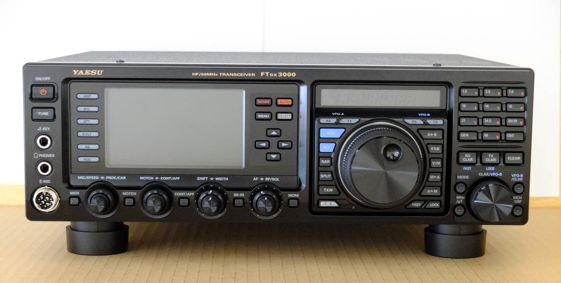
Click to zoom
Application Details
- Equipment Class
- JBP - Part 15 Class B Computing Device Peripheral
- Date of Grant
- Aug 19, 2012
- Application Purpose
- Original Equipment
- Date of Application
- Aug 19, 2012
- Equipment Note
- Scanning Receiver
- Company
- Yaesu Musen Co., Ltd.
- Country
- Japan
Documents & Files
Document Text
Text extracted from the exhibit documents filed with the FCC. Open a document above to read the original.
Users Manual
HF/50 MHz Transceiver FT DX 3000 OperaTing Manual YAESU MUSEN CO., LTD. Tennozu Parkside Building 2-5-8 Higashi-Shinagawa, Shinagawa-ku, Tokyo 140-0002 Japan YAESU USA 6125 Phyllis Drive, Cypress, CA 90630, U.S.A. YAESU UK LTD. Unit 12, Sun Valley Business Park, Winnall Close Winchester, Hampshire, SO23 0LB, U.K. YAESU HK LTD. Unit 1306-1308, 13F., Millennium City 2, 378 Kwun Tong Road, Kwun Tong, Kowloon, Hong Kong About this MAnuAl . . . The FT DX 3000 is a leading-edge transceiver with a number of new and exciting features, some of which may be unfa- miliar to you. In order to gain the most enjoyment and operating efficiency from your FT DX 3000 , we recommend that you read this manual in its entirety, and keep it handy for reference as you explore the many capabilities of your new transceiver. Before using your FT DX 3000 , be sure to read and follow the instructions in the “Before You Begin” section of this man- ual. Page 1F T DX 30 00 OperaTing Manual general DescripTiOn Congratulations on the purchase of your Yaesu amateur transceiver! Whether this is your first rig, or if Yaesu equipment is already the backbone of your station, rest assured your transceiver will provide many hours of op- erating pleasure for years to come. The FT DX 3000 is an elite-class HF transceiver pro- viding exceptional performance both on transmit and receive. The FT DX 3000 is designed for the most competitive operating situations, whether you primarily operate in contest, DX, or digital-mode environments. Built on the foundation of the popular FT DX 3000 trans- ceiver, and carrying the proud tradition of the FT-1000 series, the FT DX 3000 provides up to 100 Watts of pow- er output on SSB, CW, and FM (25 Watts AM carrier). Digital Signal Processing (DSP) is utilized throughout the design, providing leading-edge performance, both transmit and receive. For exceptional protection from strong signal interfer- ence, the optional RF μTuning Kits may be connected via the rear panel. The μTuning Kits provide extraordi- narily sharp selectivity, and protect your receiver from close-in interference on a crowded band. In the front end, you may select one of two RF pream- plifiers, or IPO (Intercept Point Optimization) providing direct feed to the first mixer. Three levels of RF attenua- tion are available in 6-dB steps. The FT DX 3000 receiver utilizes DSP filtering, incor- porating many of the features of the FT DX 9000 , such as, Variable Bandwidth, IF Shift, and Passband Contour tuning. Also provided are Digital Noise Reduction, Digi- tal Auto-Notch Filtering and a manually tuned IF Notch filter. On the transmit side, the Yaesu-exclusive Three-Band Parametric Microphone Equalizer allows precise and flexible adjustment of the waveform created by your voice and microphone. The Amplitude, Center Fre- quency, and Bandwidth are adjusted separately for the low, mid-range, and high-frequency audio spectra. The transmitted bandwidth may also be adjusted. Advanced features include: Direct Keyboard Frequency Entry and Band Change, Speech Processor, IF Monitor for Voice modes, CW Pitch control, CW Spot switch, Full CW QSK, adjustable IF Noise Blanker, and all- mode Squelch. Three TX/RX antenna ports are provided on the rear panel. Two key jacks are provided (one on the front and one on the rear panel). The key jacks may be configured independently for paddle input, connec- tion to a straight key, or computer-driven keying inter- face. The CW Message Memory is provided. Frequency setup is straightforward on the FT DX 3000 . Enter frequency directly for both VFO-A and VFO-B. Separate keys are provided for band selection. Each band key provides three separate VFO settings for three different parts of each band. You can establish three in- dependent VFO settings of frequency, mode, and filter for each band. In addition, 99 memories are provided to store: Frequen- cy, Mode, IF filter selection, Clarifier offset, and Scan- skip status. What’s more, five quick-recall (“QMB”) memories can instantly store operational settings at the push of a button. The built-in antenna tuner includes 100 memories that automatically store antenna matching settings for rapid automatic recall later. Interfacing for digital modes is extremely simple with the FT DX 3000 , thanks to the dedicated RTTY/PKT connection jack on the rear panel. Optimization of the filter passband, DSP settings, carrier insertion point, and display offset for digital modes, is possible via the Menu programming system. Advanced technology is only part of the FT DX 3000 story. Yaesu stands behind our products with a world- wide network of dealers and service centers. We greatly appreciate your investment in the FT DX 3000 , and we look forward to helping you get the most out of your new transceiver. Please feel free to contact your nearest dealer, or one of Yaesu’s national headquarters offices, for technical advice, interfacing assistance, or accessory recommendation. Watch Yaesu U.S.A.’s Home Page for late-breaking information about Standard Horizon and Yaesu products: http://www.yaesu.com. Please read this manual thoroughly, to gain maximum understanding of the full capability of the FT DX 3000 . We thank you again for your purchase! Page 2F T DX 30 00 OperaTing Manual Table OF cOnTenTs General Description .....................................................1 Accessories & Options .................................................4 Supplied Accessories ................................................4 Available Options .....................................................5 Before You Begin ..........................................................6 Extending the Front Feet ..........................................6 Adjusting the Main Tuning Dial Torque ..................6 Resetting the Microprocessor ...................................7 Resetting Memories (Only) ................................7 Menu Resetting ...................................................7 Full Reset…
Text truncated - open the document above for the full version.
Users Manual
Page 14F T DX 30 00 OperaTing Manual insT allaTiOn anD inTercOnnecTiOns interFAcing to other lineAr AMpliFierS note The TX GND OUT pin (pin 2) of the LINEAR jack is a transistor “open collector” circuit. It is capable of handling positive relay coil voltages up to +60VDC at 200 mA or +30 VDC at 1 A. If you plan to use multiple linear amplifiers for different bands, you must provide external band switching of the “Linear Tx” relay control line from the “TX GND OUT” line at the LINEAR jack. The specified range for ALC voltage to be used with the FT DX 3000 is 0 to -4 Volts DC. Amplifier systems utilizing different ALC voltages will not work correctly with the FT DX 3000 , and their ALC lines must not be connected if this is the case. iMportAnt note! Do not exceed the maximum voltage or current rat- ings for the “TX GND OUT” pin (pin 2) of the LIN- EAR jack. This line is not compatible with negative DC voltages, or AC voltages of any magnitude. Most amplifier control relay systems require only low DC voltage/current switching capability (typi- cally, +12V DC at 25 ~ 75 mA), and the switching transistor in the FT DX 3000 will easily accommodate such amplifiers. Wire Color Orange Yellow Green Red White Blue Violet Brown Black Gray Light Blue LINEA Jack ( Pin Number ) 1 2 3 4 5 6 7 8 9 10 Case Function +13.8 V TX GND GND BAND DATA A BAND DATA B BAND DATA C BAND DATA D TX INH EXT ALC IN TX REQ IN Shield Linear Amplifier Connection Cable ( T9207451 ) Color Code Information Note When the FC-40 is connected to the FT DX 3000 , TX GND (pin 2) of the TUNER jack and the LINEAR jack (pin 2) are common circuits. Therefore, the maximum voltage at TX GND (pin 2) of the LINEAR jack must not exceed +5V. Page 15F T DX 30 00 OperaTing Manual plug/cOnnecTOr pinOuT DiagraMs Page 16F T DX 30 00 OperaTing Manual [ POWER ] Switch Press and hold in this switch for one second to turn the transceiver on. Similarly, press and hold in this switch for one second to turn the transceiver off. [ TUNE ] Switch This is the on/off switch for the FT DX 3000 ’s Auto- matic Antenna Tuner. Pressing this button momentarily places the antenna tun er in lin e bet ween the tra nsmitter fina l amp lifier and the antenna jack (The “ ” icon will ap- pear in the display). Reception is not affected. Pressing and holding in this button for two seconds, whi le rec eiving in an ama teur ban d, act ivates the tra nsmitter for a few sec onds whi le the aut omatic antenna tuner rematches the antenna system imped- ance for minimum SWR. The resulting setting is au- tomatically stored in one of the antenna tuner’s 100 memories, for instant automatic recall later when the receiver is tuned near the same frequency. Pressing this button momentarily, while the Tuner is engaged, will take the Automatic Antenna tuner out of the transmit line. Note: When the Automatic Antenna Tuner is tuning itself, a signal is being transmitted. Therefore, be certain that an antenna or dummy load is connected to the selected antenna jack before pressing and holding in the [ TUNE ] button to start antenna tuning. KEY Jack This 1/4-inch, 3-contact jack accepts a CW key or keyer paddles (for the built-in electronic keyer), or output from an external electronic keyer. Pinout is shown on page 15. Key up voltage is +3.3 V DC, and key down current is 0.3 mA. This jack may be configured for keyer, “Bug”, “straight key”, or computer keying interface operation via Menu item “ 018 KEYER F KEYER TYPE ” (see page ???). There is another jack with the same name on the rear panel, and it may be configured independently for Internal Keyer or pseudo-straight-key operation. Note: You cannot use a 2-contact plug in this jack (to do so produces a constant “key down” condition). FrOnT panel COnTrOls & swiTChes Page 17F T DX 30 00 OperaTing Manual FrOnT panel COnTrOls & swiTChes PHONES Jack A 1/4-inch, 3-contact jack accepts either monaural or stereo headphones with 2- or 3-contact plugs. When a plug is inserted, the loudspeaker is disabled. Note: When wearing headphones, we recommend that you turn the AF Gain levels down to their lowest settings before turning power on, to minimize the impact on your hearing caused by audio “pops” during switch- on. Microphone Connector This 8-pin jack accepts input from a microphone uti- lizing a traditional YAESU HF transceiver pinout. [ ANT ] Switch Pressing this switch selects the ANT 1 , ANT 2 or the ANT 3 connector on the rear panel, and allows convenient antenna switching at the press of button. The selected antenna jack is indicated on the Block Diagram Display shown in the Transceiver Display. [ IPO ] ( INtercept poINt optImIzatIoN ) Switch This button may be used to set the optimum front end characteristics of the receiver circuit for a very strong signal environment. Available selections are AMP 1 (low distortion amplifier), AMP 2 (2-stage low-distortion RF amplifier), or IPO (bypasses the front end RF amplifier), and the selected receiver RF amplifier appears in the IPO column of the Block Diagram Display on the display. [ ATT ] Switch This button selects the degree of attenuation, if any, to be applied to the receiver input. Available selections are –6 dB, –12 dB, –18 dB, or OFF. The attenuation level appears in the ATT col- umn of the Block Diagram Display on the display. advIce: The Attenuator may be used in conjunction with the [ IPO ] button to provide two stages of signal reduc- tion when an extremely strong signal is being re- ceived. [ R.FLT ] ( roofINg fIlter ) Switch This button selects the bandwidth of the receiver first IF Roofing Filter. Available selections are 3 kHz, 6 kHz, 15 kHz, or Auto. The selected bandwidth ap- pears in the R.FLT column of the Block Diagram Display on the display. advIce: Because the roofing filter is in the first IF, the pro- tection it provides against interference is quite sig- nificant. Whe n set to AUT O, SSB ban dwidth is 6 kHz, CW is 3 kHz, FM and RTTY are 15 kHz. On a crowded SSB band, howe…
Text truncated - open the document above for the full version.
Users Manual
Page 29F T DX 30 00 OperaTing Manual rear panel ANT 1/2/3 Jacks Connect your main antenna(s) here, using a type-M (PL-259) connector and coaxial feed lines. The in- ternal antenna tuner affects only the antenna(s) con- nected here, and only during transmission. Warning! The 100V RF voltage (@100 W/50 ) is applied to the TX RF section of the transciver while trans- mitting. Do not touch the TX RF section abso- lutely while transmitting. DC IN Jack This is the DC power supply connection for the transceiver. Use the supplied DC cable to connect di- rectly to a DC power supply, which must be capable of supplying at least 23 A @13.8 VDC. GND Use this terminal to connect the transceiver to a good earth ground, for safety and optimum performance. Use a large diameter, short braided cable for making ground connections, and please refer to page 9 for other notes about proper grounding. To prevent the damage from a thunder, at- mospheric electricity, electrical shock etc., please take a good earth ground. μ-TUNE Jacks These jacks are used to connect the optional RF μTuning Kit, signal in and signal out. +13.8 V Jack This RCA output jack provides regulated, separately fused 13.8 VDC at up to 200 mA, to power an ex- ternal device such as a packet TNC. Make sure your device does not require more current (if it does, use a separate power source). PTT Jack This RCA input jack may be used to provide manual transmitter activation using a footswitch or other switching device. Its function is identical to the [ MOX ] button on the front panel. The same line is available at the RTTY/PKT jack for TNC control. Open-circuit voltage is +5 VDC, and closed-circuit current is 1 mA. EXT ALC Jack This RCA input jack accepts negative-going exter- nal ALC (Automatic Level Control) voltage from a linear amplifier, to prevent over-excitation by the transceiver. Acceptable input voltage range is 0 to –4 VDC. IF OUT Jack This RCA input jack outputs the 9 MHz IF signal of the received signal when Menu item “109 RGEN IF OUT” is set to “ ENABLED ”. This signal does not pass through the roofing filter. TX GND Jack This RCA jack’s center pin is closed to ground while the transceiver’s transmitter is engaged. RX OUT Jack This RCA input jack provide output of the receiver signal lines from the Antenna jack. LINEAR Jack This 15-pin output jack provides band selection data, which may be used for control of optional accesso- ries such as the VL-1000 Solid-state Linear Ampli- fier. Page 30F T DX 30 00 OperaTing Manual rear panel ROTATOR Jack This covered 6-pin MINI-DIN Jack accepts a cable to connect to a YAESU G-800DXA / -1000DXA/ -2800DXA (for USA/EXP market) or G-800DXC / -1000DXC/-2800DXC (for European market) An- tenna Rotator (listed models are current as of early 2012). You may control the antenna azimuth rotation (and rotation speed) using the Function buttons on the front panel. TUNER Jack This 8-pin output jack is used for connection to the FC-40 External Automatic Antenna Tuner. RTTY/PKT Jack This 6-pin input/output jack accepts AFSK input from a Terminal Node Controller (TNC); it also provides fixed level (100-mV @600 Ohms) receiver audio output, and FSK keying line. LINE Jack T.B.D. REM ( REMOTE ) Jack By plugging in the optional FH-2 Remote Control Keypad to this gold-plated jack, direct access to the FT DX 3000 CPU is provided for control functions such as contest memory keying, plus frequency and function control. EXT SPKR Jack This 3.5-mm, 2-contact, gold-plated jack provides variable audio output for an external loudspeaker. The audio output impedance at this jack is 4 - 8 Ohms, and the level varies according to the setting of the front panel [ AF GAIN ] knob. Inserting a plug into this jack disables the internal loudspeaker. KEY Jack This 1/4-inch 3-contact jack accepts a CW key or keyer paddle. A two-contact plug cannot be used in this jack. Key-up voltage is +3.3 V DC, and key- down current is 0.3 mA. This jack may be config- ured for keyer, “Bug”, “straight key”, or computer keying interface operation via Menu item “ 039 A1A R-TYPE ”. μ-TUNE Jack This covered 10-pin mini-DIN jack is used for con- trol of the optional RF μTuning Kit. CAT Jack This 9-pin serial DB-9 jack allows external computer control of the FT DX 3000 . Connect a serial cable here and to the RS-232C COM port on your personal computer (no external interface is required). USB Jack T.B.D. PGM-SW Switch This slide switch is used for updating the transceiv- er’s firmware. The update software and instructions are available for download from the YAESU website (http://www.yaesu.com/). Page 31FT DX 3000 OperaTing Manual Before turning on main power, please verify the following items once more. Have you made all ground connections securely? See page ?? for details. Do you have your antenna(s) connected to the rear-panel Antenna jack(s)? See page ?? for details. Is your microphone (and/or key or paddle) connected? See page ?? for details. If using a linear amplifier, have all interconnections been successfully completed? See page ?? for details. Please rotate the [ AF GAIN ] control to the fully counter-clockwise position, to avoid a loud blast of audio when the transceiver turns on. See page ?? for details. Basic OperaTiOn: receiving On aMa Teur BanDs Page 32FT DX 3000 OperaTing Manual Here is the typical start-up procedure for normal operation: 1. Turn on the external DC power supply. 2. Press and hold in the front-panel [ POWER ] switch until the transceiver turns on. After about five seconds (ten seconds if the optional μ-Tuning Kit is connected), the transceiver is ready for full operation. 3. The transceiver will start up on 7.000.00 MHz LSB, and normal operation may begin. Note: To turn power off, press and hold in the front panel [ POWER ] switch for two seconds. 4. Rotate the [ AF GAIN ] knob to set a comfortable audio level on in- coming signals or noise. Clockwise rotation of the [ AF GAIN ] knob increases the volume level. Note: W…
Text truncated - open the document above for the full version.
Users Manual
Page 34FT DX 3000 OperaTing Manual opeRA tioN oN 60-MeteR ( 5 MHz ) bANd ( u.s. ANd u.K. veRsioN oNly ) The recently-released 60-meter band is covered, in the FT DX 3000 , by fixed memory channels. These channels are set to USB, and they appear between the “last” PMS channel (“ P9U ”) and the first “regular” memory channel (Channel 1): 1. Press the [ V/M ] button once to enter the “Memory” mode; the “ MCH ” icon will appear in the display and a memory channel number will appear on the display. Advice: If you can not enter the “Memory” mode, check to see if the transceiver is in VFO-B mode (the green [( VFO-B ) RX ] Indicator/Switch is illuminated). If so, press the [( VFO-A ) RX ] Indicator/Switch to return operation to VFO-A. Now, press the [ V/M ] button to enter the “Memory” mode. 2. Press the [ MCH ] button located on the bottom right of the [ CLAR/VFO-B ] knob. The LED imbedded in the button will glow orange to signify that rotation of the [ CLAR/VFO-B ] knob will allow selection of the memory channel. 3. Memory channels (“ 5M-01 ” through “ 5M-10 ”) are pre-programmed, at the factory, with the permitted frequencies in the 5 MHz band, and the USB mode is automatically selected on these channels. 4. To exit from 60-meter operation and return to the VFO mode, just press the [ V/M ] button. Note: The frequencies and operating mode for 5 MHz band operation are fixed, and may not be changed. Basic OperaTiOn: receiving On aMa Teur BanDs [ CLAR/VFO-B ] Knob [ VFO-B ( RX )] Button [ MCH ] Button [ V/M ] Button [ VFO-A ( RX )] Button Main Tuning Dial Knob cHANNel NuMbeR 5M-01 5M-02 5M-03 5M-04 5M-05 5M-06 5M-07 5M-08 5M-09 5M-10 FReQueNcy 5.332000 MHz 5.348000 MHz 5.358500 MHz 5.373000 MHz 5.405000 MHz 5.332000 MHz 5.348000 MHz 5.358500 MHz 5.373000 MHz 5.405000 MHz Page 35FT DX 3000 OperaTing Manual Basic OperaTiOn: receiving On aMa Teur BanDs clAR ( clARiFieR ) opeRA tioN The [ RX CLAR ] , [ TX CLAR ] , [ CLEAR ] buttons and [ CLAR/VFO-B ] knob are used to offset the receive frequency, the transmit frequency, or both, from their settings on the VFO-A frequency. Four small numbers on the Multi-Display Window show the current Clarifier offset. The Clarifier controls on the FT DX 3000 are designed to allow you to preset an offset (up to ±9.999 kHz) without actually retuning, and then to activate it via the Clarifier’s [ RX CLAR ] and [ TX CLAR ] buttons. This feature is ideal for following a drifting station, or for setting small frequency offsets sometimes utilized in DX “Split” work. Here is the technique for utilizing the Clarifier: 1. Press the [ RX CLAR ] button. In the Multi-Display Window, the “ RX ” notation will appear, and the programmed offset will be applied to the receive fre- quency. 2. Rotation of the [ CLAR/VFO-B ] knob will allow you to modify your initial offset on the fly. Offsets of up to ±9.99 kHz may be set using the Clarifier. To cancel Clarifier operation, press the [ RX CLAR ] but- ton. The “ RX ” notation will disappear from the display. Advice: Turning the Clarifier off simply cancels the applica- tion of the programmed offset from the receive and/ or the transmit frequencies. To clear the Clarifier offset, and reset it to “zero,” press the [ CLEAR ] but- ton. The programmed offset is displayed in the small multi-channel window of the frequency display. You may also activate the clarifier on the VFO-B fre- quency. In this case, the offset frequency is set using the Main Tuning Dial knob, instead of the [ CLAR/ VFO-B ] knob. The Clarifier operation (including the offset frequen- cy) will be memorized independently on each VFO stack of VFO-A and VFO-B. [ CLAR/VFO-B ] Knob [ RX CLAR ] Button [ TX CLAR ] Button [ CLEAR ] Button TXCLAR Alternately, You may apply the Clarifier offset to the transmit frequency, without changing the receive frequency (typically, for “split” DX pile- ups). [ CLAR/VFO-B ] Knob [ p / q ] Button The Tuning Offset Indicator provides a graphical representation of the Clarifier offset. In the factory default setting On CW, the Tuning Offset Indicator is used for CW Cen- ter Tuning, instead of Clarifier Offset. If you wish to change this so that the Clarifier Offset is also displayed on CW, use the following procedure: [ Plus ( + ) Offset ] [ Zero Offset ] [ Minus (–) Offset ] [ SELECT ] button 1. Press and hold in the [ MENU ] button for one second to enter the Menu mode. 2. Rotate the [ CLAR/VFO-B ] knob or p / q button to select Menu item “ 011 DISPLAY BAR DIS- PLAY SELECT ”. 3. Press the [ SELECT ] button then rotate the [ CLAR/VFO-B ] knob or p / q button to select “ CLAR (Clarifier)” (replacing the default “ CW TUNE (CW TUNING)” selection). 4. Pre ss the [ SELECT ] button, then press the [ MENU ] button to save the new setting and exit to normal operation. Multi-Display Window [ MENU ] button Page 36FT DX 3000 OperaTing Manual Basic OperaTiOn: receiving On aMa Teur BanDs LOCK You may lock the setting of the Main Tuning Dial knob (for VFO-A frequency tuning) and the [ CLAR/VFO-B ] knob (for VFO-B frequency tuning), to prevent accidental frequency change. Main Tuning Dial knob Lock To lock the Main Tuning Dial knob, press the [( VFO-A ) RX ] Indicator/Switch to illuminate the imbedded green LED, then press the [ LOCK ] button that is located to the right of the Main Tuning Dial knob. To unlock the Dial setting, and restore normal tuning, press the [ LOCK ] button once more. [ CLAR/VFO-B ] knob Lock To lock the [ CLAR/VFO-B ] knob, press the [ VFO-B / CLAR ] button that is located to the right of the [ CLAR/ VFO-B ] knob. Indicator/Switch to illuminate the imbed- ded orange LED, then press the [ TX CLAR (LOCK) ] button that is located to the top of the [ CLAR/VFO-B ] knob. To unlock the [ CLAR/VFO-B ] knob, and restore normal tuning, press the [ TX CLAR (LOCK) ] button once more. Advice: The lock feature will be memorized independently on each Main Tuning Dial knob and the [ CLAR/VFO-B ] knob. DIMMER The illumination level of the display m…
Text truncated - open the document above for the full version.
Users Manual
Page 40FT DX 3000 OperaTing Manual RotAtoR coNtRol FuNctioNs When using a YAESU model G-800DXA , G-1000DXA , G-2800DXA Antenna Rotator (not supplied), it is possible to control it from the front panel of the FT DX 3000 . 1. Press and hold in the [ ENT ] button (one of the [ BAND ] key switches) for one second. The Fre- quency Display area will change over to the “Rotator Control” configuration. 2. Press either the [ 3.5 ( 2 )] button or the [ 7 ( 3 )] button to rotate the antenna. Pressing the [ 3.5 ( 2 )] button will cause rotation to the left (counter-clockwise) by two degree steps, while pressing the [ 7 ( 3 )] button will cause rotation to the right (clockwise) by two degree steps. 3. Press the [ 14 ( 5 )] button or the [ 18 ( 6 )] button to con- trol the speed of rotation. Pressing the [ 14 ( 5 )] button will cause slower rotation, while pressing the [ 18 ( 6 )] button will speed up rotation. Usually, you will be using the “100%” speed setting. When you are through exercising rotator control, press the [ ENT ] button momentarily. The Frequency Display will return to the main display field. iMpoRtANt Note Set the starting point to match your rotator control indicator needle via the Menu item “ 014 DISPLAY ROTATOR START UP ”. The default setting is zero (north). If your control- ler starting point is south, the Menu item “ 014 DISPLAY ROTATOR START UP ” must be set to “ 180 ”. If not set properly the FT DX 3000 display will not show the correct direction. When the rotator control indicator needle does not indicate the precise antenna direc- tion, calibrate the indicator needle precisely to the antenna direction via the Menu item “ 015 DISPLAY ROTATOR OFFSET ADJ ”. cOnvenience FeaTures [ 3.5 ( 2 )] , [ 7 ( 3 )] Button [ 14 ( 5 )] , [ 18 ( 6 )] Button [ ENT ] Button Counter-clockwise Rotation Clockwise Rotation Speed Down Speed Up Remove the rubber cap first, and then connect the plug. Page 41FT DX 3000 OperaTing Manual MoRe FReQueNcy NAvigA tioN tecHNiQues cOnvenience FeaTures [ DWN ] Button [ FST ] Button [ UP ] Button Keyboard Frequency Entry You may enter operating frequencies directly into the current VFO, using the front panel [ BAND ] key buttons. Example: Enter 14.250.00 MHz 1. Press the [ ENT ] but- ton to engage the direct frequency entry process. Now, beginning with the first digit of the frequency (the leftmost digit), we will enter the required digits of the frequency. 2. Press, in order, the digits of the operating frequency, using the [ BAND ] buttons (the frequency entry digit or decimal point is printed on the right side of the buttons). In this example, enter [ 1.8 ( 1 )] [ 10 ( 4 )] [ GEN ( . )] [ 3.5 ( 2 )] [ 14 ( 5 )] [ 50 ( 0 )] [ 50 ( 0 )] [ 50 ( 0 )] [ 50 ( 0 )] The decimal point after the “MHz” portion of the frequency must be entered, but no decimal point is required after the “kHz” portion. 3. Press the [ ENT ] button once more. A short “beep” will confirm that the frequency entry was successful, and the new operating frequency will appear on the display. Advice: If you attempt to enter a frequency outside the oper- ating range of 30 kHz ~ 56 MHz, the microprocessor will ignore the attempt, and you will be returned to your previous operating frequency. If this happens, please try again, taking care not to repeat the error in the frequency entry process. Using the [ CLAR/VFO-B ] knob You may change the cur- rent VFO frequency in 1 MHz steps. Press the [ MHz ] button located at the bot- tom and left of the [ CLAR/ VFO-B ] knob. The 1 MHz steps will be applied to the current VFO frequency. The imbedded LED in the [ MHz ] button will glow orange in the latter case. When tuning in 1 MHz steps, clockwise rotation of the [ CLAR/VFO-B ] knob will increase the frequency, while counter-clockwise rotation will decrease the frequency. Using the [ UP ] / [ DWN ] buttons of the supplied MH-31 B8 Hand Microphone The [ UP ] / [ DWN ] buttons on the supplied MH-31 B8 Hand Microphone may also be used to manually scan the frequency upward or downward. The microphone’s [ UP ] / [ DWN ] buttons utilize the tuning steps of the Main Tuning Dial knob. When the microphone’s [ FST ] button is pressed, the tuning rate increases by a factor of ten, in a manner similar to the transceiver front panel [ FST ] button. Advice: You may independently set the tuning steps of the [ UP ] / [ DWN ] buttons in the AM and FM modes. To set new tuning steps, use Menu items “ 154 TUNING AM CH STEP ” and “ 155 TUNING FM CH STEP ”. Page 42FT DX 3000 OperaTing Manual ReceiveR opeRA tioN ( FRoNt eNd blocK diAgRAM ) The FT DX 3000 includes a wide range of special features to suppress the many types of interference that may be en- countered on the HF bands. However, real world interference conditions are constantly changing, so optimum setting of the controls is somewhat of an art, requiring familiarity with the types of interference and the subtle effects of some of the controls. Therefore, the following information is provided as a general guideline for typical situations, and a starting point for your own experimentation. The FT DX 3000 ’s interference-fighting circuitry begins in its “RF” stages, and continues throughout the entire receiver section. FT DX 3000 allows configuration of the features described below. R. FLT ( IF Roofing Filters ) Three Roofing filters, of 15 kHz, 6 kHz, and 3 kHz bandwidths, are provided in the 69 MHz First IF, right after the first mixer. These filters are automatically se- lected to provide narrow-band selectivity to protect the following IF and DSP stages. The automatically selected filter, may be manually changed by the operator, if de- sired, for special operating circumstances. CONTOUR Filter The DSP Contour filter has the unique ability to pro- vide either a null or a peak in tunable segments of the receiver passband. You may suppress interference and excessive frequency components on an incoming signal, or you may peak those tunable frequency segme…
Text truncated - open the document above for the full version.
Contact Information
Applicant
Masatoshi Muraishi(Engineering Division)
Technical Contact
PCTEST Engineering Lab., Inc.Randy Ortanez
[email protected]410-290-6652
6660-B Dobbin Road · Columbia, Maryland · United States
Test Firm
Intertek Japan K.K.(Kashima Laboratory)Junichi Okada
Technical Specifications
| # | Rule Parts | Frequency Range | Power Output |
|---|---|---|---|
| 1 | 15B | - | - |
Other Applications from Yaesu Musen Co., Ltd.
K660E180X10
Dec 01, 2025BLUETOOTH MICROPHONE
Equipment Class
DTS - Digital Transmission System
K6630673Y3D
Aug 01, 2024VHF FM Marine Transceiver
Equipment Class
CXX - Communications Rcvr for use w/ licensed Tx and CBs
K6630653Y3D
Aug 01, 2024VHF FM Marine Transceiver
Equipment Class
CXX - Communications Rcvr for use w/ licensed Tx and CBs
K6630683X30
Jan 10, 2023VHF FM Marine Transceiver
Equipment Class
TNF - Licensed Non-Broadcast Transmitter Held to Face
K6650033X30
Nov 18, 2020Airband Radio Transceiver
Equipment Class
TNF - Licensed Non-Broadcast Transmitter Held to Face