K6620485X40Amateur Radio with scanning receiver
Yaesu Musen Co., Ltd.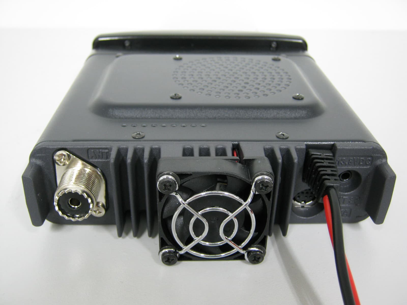
Click to zoom
Application Details
- Equipment Class
- CSR - Scanning Receiver
- Date of Grant
- Apr 07, 2015
- Application Purpose
- Original Equipment
- Date of Application
- Apr 07, 2015
- Equipment Note
- Amateur Radio with scanning receiver
- Frequency Range
- 800.00000000 - 999.00000000
- Company
- Yaesu Musen Co., Ltd.
- Country
- Japan
Documents & Files
Document Text
Text extracted from the exhibit documents filed with the FCC. Open a document above to read the original.
Users Manual
C4FM FDMA 144/430MHz DUAL BAND TRANSCEIVER FTM-100DR Operating Manual Before Using Installation and Connection Basic Operations Using the Memory Scanning Using the GPS Function Using the APRS Function Using the GM Function Convenient Function Functions to be used when Necessary Customize Menu Settings and User Preferences Appendix 2 Before Using Introduction Features of this radio 144/430 MHz dual band mobile radio equipped with standard C4FM digital communication modem Clear audio and data communication is achieved using the digital modem functions Wide band receive in the 108 MHz to 999 MHz range (wireless business, public service and air band) Transmission power FTM-100DRStandard modelTransmission power 50W The dot matrix LCD is mounted on the controller 500 memory channels in the Band A (band at the top of the display) and 500 channels in the Band B (band at the bottom of the display) The frequency and settings memories can be saved, using a micro-SD card. The data in the micro-SD card can easily be copied to other radios Diverse range of scanning functions (VFO scan, memory scan etc.) Built-in GPS receiver unit, location and movement information can be displayed and GPS data can be output to connected devices Incorporated APRS ® functions. Position, movement data and messages can be communicated to other stations, digipeaters and the Internet. *Refer to the separate “APRS Operating Manual” GM (Group Monitor) function where in a group of frequently communicating members can be registered, and then position information and messages can be exchanged *Refer to the separate “GM Operating Manual” Supports Yaesu WIRES-X Internet linking, providing communication with remote partners using the Internet *Refer to the separate “WIRES-X Operating Manual” Bluetooth adaptor unit BU-2 (sold separately) permits hands-free operation Voice guide unit FVS-2 (sold separately) provides frequency voice announcement, and recording of received audio * The APRS, GM and WIRES-X Operating Manuals are not included with the product. Please download them from the Yaesu website. 3 Before Using Introduction Important precautions for mobile radio operation The use of protective tape or covering is recommended to protect the wiring and the power cord inside the vehicle. When installing the unit inside a vehicle, locate the radio, antenna, co-axial cable, etc. at least 20 cm away from the following control equipment. ● Engine-relate d: Fuel injection equipment and engine control ● Transmission-related: Transmission and 4WD electronic control unit ● Others: ECS/EPS/ABS/ETACS/Fully automatic air-conditioner/ Auto-heater control unit/G sensor Install the antenna and co-axial cable away from the control unit and wiring harness. Place all cables so they do not entangle and impede the driver or passengers. Never place any equipment in a location where it may pose a danger to the passengers, where it may interfere with driving, or obstruct the driver field of view. Do not install any apparatus in such a way that it may interfere with the proper operation of the air bags. After installing the radio, check that the brake lamp, head lamp, turning indicator lights, wiper, etc. are working normally with the radio power switched on. Keep full attention on driving, do not operate the radio controls or look at the radio display while driving. Stop the vehicle at a safe location, before operating the radio controls or looking at the display. Do not drive the car in such a way that external sounds required for safe driving cannot be heard. Most areas and districts prohibit the use of earphones and headphones while driving. When using the radio transmitter, if it appears to have abnormal effects on the control equipment of the vehicle, stop the engine, turn off the power supply , and disconnect the power cord. Resolve the problem before continuing to operate the radio equipment. When using the radio in an electric or hybrid car, the receiver may experience high RF interference and noise from the inverters that are built into the electric vehicle. 4 Before Using Introduction How to read this manual In this manual, controller operations are expressed as follows: Press ............................................Indicates that the key or switch is to be pressed quickly. Press for 1 second or longer .........Indicates that the key or switch is to be pressed for one second or longer. Select [MODE] ...................................Indicates that the items are to be highlighted on the touch panel screen. The following symbols are also used in this manual: Caution ...Explains information to avoid incorrect operation. Tip ...Explains operating hints and helpful advice. Also note: the actual product may differ from the drawings shown in this manual. 5 Before Using Safety Precautions (make sure to read these) Make sure to read this manual in order to use this radio safely and correctly. Note beforehand that the company shall not be liable for any damages suffered by the customer or third parties in using this product, or for any failures and faults that occur during the use or misuse of this product, unless otherwise provided for under the law. Type and meaning of the marks DANGER This symbol indicates the possibility of death or serious injury being inflicted on the user and the surrounding people when these instructions are ignored and the product is handled wrongly. WARNING This symbol indicates the possibility of death or serious injury being inflicted on the user and the surrounding people when these instructions are ignored and the product is handled wrongly. CAUTION This symbol indicates the possibility of physical impediments occurring or impediments being inflicted on the user and the surrounding people when these instructions are ignored and the product is handled wrongly. Type and meaning of symbols Prohibited actions that must not be carried out in order to use this radio safely. For ex…
Text truncated - open the document above for the full version.
Users Manual
17 Before Using Connecting the Radio Connecting the controller to the main body Caution Make sure the power supply is switched OFF before connecting the cable between the controller and the main body. 1 Plug the connector of the controller cable into the [CONTROL] jack at the front of the main body until a click sound is heard Main body Controller cable 2 Plug the other connector of the controller cable into the [CONTROL] jack at the back of the controller until a click sound is heard Controller cable Controller Connecting the microphone 1 Plug the microphone connector into the [MIC] jack at the front of the main body until a click sound is heard Tips • To remove the microphone, pull the connector out while pressing the latch. • Using the optional microphone extension kit “MEK- 2”, a microphone with a 8-pin connector can be used. A microphone extension cable (about 3 m long) is also included in MEK-2. Use it to install the microphone in locations which cannot be reached by the attached microphone cable. LOCK P3 P2 P 1 7 1 4 8 2 0 5 9 B A C D 3 6 P4 LAMP DTMF MICROPHONE MH-48 ABC JKL TUV GHI PQRS DEF MNO WXYZ MIC Connector Microphone Connecting the antenna 1 Attach the antenna co-axial cable to the [ANT] terminal at the back of the main body and tighten the connector 同軸ケーブル端子 本体(後面) Main body (rear side) Co-axial cable connector 18 Before Using Connecting the Radio Connecting the external power supply equipment When using this radio as a fixed station, use an external 12 V DC power source. Cautions zUse an external power source capable of supplying DC 13.8 V, a current capacity of 20 A or more (FTM-100DR). zMake sure to switch OFF the power of the external power source before connecting. 1 Connect the red wire (+) of the provided DC power supply cable to the positive (+) terminal of the external power source, and the black wire (-) to the negative (-) terminal of the external power source 2 Connect the DC power supply cable to the connector of the power cord of the main body Press the plug into the connector until a click sound is heard. Power cord (DC (direct current) 13.8 V) Rear side of main body Black Red AC line outlet DC power supply cable (accessory) Fuse holder Direct current 13.8 V DC power supply 19 Before Using Setting Up the micro-SD Card The following operations can be carried out by using a micro-SD card in this radio. • Backing up the information and settings of the radio • Saving the information in the memory channels • Saving the settings in the set-up mode • Saving the GPS log data • Saving data that has been downloaded using the GM function and WIRES-X function • Exchanging the saved data among multiple radios Micro-SD cards that can be used 2 GB, 4 GB, 8 GB, 16 GB and 32 GB micro-SDHC cards can be used in this radio. Cautions zThe micro-SD or micro-SDHC cards are not provided with the product. zNot all micro-SD and micro-SDHC cards sold commercially are guaranteed to work with this product. Things to note when using micro-SD cards • Do not bend the micro-SD card or place heavy objects on top of it. • Do not touch the terminal face of the micro-SD card with your bare hands. • Micro-SD cards that are initialized in other devices may not record normally when used in this device. Re-initialize the micro-SD card in this radio when using a card that has been initialized in another device. (Refer to Page xx on how to initialize the memory card) • Do not pull the micro-SD card out, or switch the power to the radio OFF when reading or writing data to the card. • Do not insert anything other than a micro-SD card into the micro-SD card slot of the radio. • Do not pull out or insert the micro-SD card with unreasonable force. • When a single micro-SD card is used for a long period of time, writing and deletion of data may become disabled. Use a new micro-SD card when data can no longer be written or erased. • Note that Yaesu shall not be liable for any damages suffered as a result of data loss or corruption in use of the micro-SD card. 20 Before Using Setting Up the micro-SD Card Installing the micro-SD card 1 Press for 2 seconds or longer to switch off the power to the main body 2 Insert the micro-SD card into the micro-SD card slot, with the terminal face on top, until a click sound is heard Cautions z Insert the micro-SD card in the correct direction. z Do not touch the terminal of the micro-SD card with your hands. Terminal face microSD card slot microSD card After the power is switched on, the “” icon will be displayed at the top right of the display. Tip It may take a while for the icon to appear depending on the card capacity. Removing the micro-SD card 1 Press for 2 seconds or longer to switch off the power to the main body 2 Push in on the microSD card A click sound will be heard and the micro-SD card will be pushed outward. 3 Pull the micro-SD card from the micro-SD card slot 21 Before Using Setting Up the micro-SD Card Initializing the micro-SD card When using a new micro-SD card, initialize the micro-SD card according to the following procedure. Caution Upon initialization, all the data recorded in the micro-SD card will be erased. Check the contents of the micro-SD card before initialization. 1 Press for one second or longer The set-up menu will be displayed. 2 Turn the DIAL to select [11 SD], then press The menu list will be displayed. 3 Turn the DIAL to select [4 FORMAT], then press The format confirmation screen will be displayed. 4 Turn the DIAL to select [OK?], then press The micro-SD card will be initialized. Tip To cancel initialization, turn the DIAL to select [Cancel], then press . “Completed” will be displayed when initialization is completed and the screen will then return to the menu list. 22 Before Using Receiving Turning the power on 1 Press for 2 seconds or longer The power will be switched on, and the display will appear on the screen. Tips • When switching the power on for the first time after purchasing, or after resetting, a screen requesting the cal…
Text truncated - open the document above for the full version.
Attestation Statements
February 26, 2015 Federal Communications Commission Authorization and Evaluation Division, 7435 Oakland Mills Road Columbia, MD 21046 USA Re: FTM-100DR (FCC ID: K6620485X40) Gentlemen: The scanner receiver equipment meets the requirements of the FCC Rules, 15.121 (a). Compliance is achieved through the following methods: The scanner receiver in this equipment is incapable of tuning, or readily being altered, by the User to operate within the frequency bands allocated to the Domestic Public Cellular Telecommunications Service in Part 22. Blocking of the cellular frequencies is implemented in the firmware of the unit’s main control central processing unit (CPU). Coverage of 824 - 849 MHz and 869 - 894 MHz is completely blocked, since it is done in the microprocessor, and cannot be re-enabled by any user-accessible procedure, including diode, resistor, or jumper changes, nor by connection of any external device such as a personal computer, nor by installation of any “special” enabling semiconductor device. The scanning receiver is designed so that the tuning, control and filtering circuitry is inaccessible. Sincerely, YAESU MUSEN CO., LTD. Kouji Taguchi Engineering Division / Quality Assurance
Attestation Statements
February 26, 2015 Federal Communications Commission Authorization and Evaluation Division, 7435 Oakland Mills Road Columbia, MD 21046, USA Re: FTM-100DR (FCC ID: K6620485X40) Gentlemen: A. Part 15.19 & 15.21 Compliance Statement Drawing: B. Part 15.19 & 15.21 Compliance Statement Drawing Location: IN OPERATION MANUAL (location on inside back cover) Sincerely, YAESU MUSEN CO., LTD. Kouji Taguchi Engineering Division / Quality Assurance 1. Changes or modifications to this device not expressly approved YAESU MUSEN could void the user’s authorization to operate this device. 2. This device complies with part 15 of the FCC rules. Operation is subject to the following two conditions; (1) This device may not cause harmful interference, and (2) this device must accept any interference including interference that may cause undesired operation. 3. The scanning receiver in this equipment is incapable of tuning, or readily being altered, by the user to operate within the frequency bands allocated to the Domestic public Cellular Telecommunications Service in the Part 22.
Cover Letter(s)
February 26, 2015 Federal Communications Commission EQUIPMENT APPROVAL SERVICES P. O. Box 358315 Pittsburgh, PA 15251-5315 Attention: Authorization and Evaluation Division Reference: FTM-100DR (FCC ID: K6620485X40) Pursuant to Sections 0.457 (d) (1) (ii) and 0.459 of the Commission’s Rules, the Applicant hereby requires confidential treatment of some of the information accompanying this Application, as listed below: Confidential ・ Block Diagram ・ Schematics ・ Operation Description (Circuit Description) ・ Parts List ・ Internal Photos Short-Term Confidential ・ Operating Manual ・ External Photos These materials contain trade secrets and proprietary information not customarily released to the public. The public disclosure of these matters might be harmful to the Applicant and provide unjustified benefits to its competitors. The Applicant understands that pursuant to Rule 0.457 (d) ( 1) (ii), disclosure of the Application and all accompanying documentation will not be made before the date of Grant for this Application. Sincerely, YAESU MUSEN CO., LTD. Kouji Taguchi Engineering Division / Quality Assurance
ID Label/Location Info
FTM-100DR ID DRAWING YAESU MUSEN CO., LTD. ID and CAUTION drawings CAUTION drawings Label location ID drawing Model: Title: Model:FTM-100DR MADE IN JAPAN YAESU MUSEN CO., LTD. IC:511B-20485X40 FCC ID:K6620485X40 5E000000 788026000000 2:1 1:1
Test Report
FCC PART 15 SCANNING RECEIVER Applicant YAESU MUSEN CO., LTD. Address TENNOZU PARKSIDE BUILDING 2-5-8 HIGASHI-SHINAGAWA, SHINAGAWA-KU, TOKYO 140-0002 JAPAN FCC ID: K6620485X40 Model Number FTM-100DR Product Description AMATEUR RADIO W/ SCANNING RECEIVER Date Sample Received 3/10/2015 Date Tested 3/25/2015 Tested By Sid Sanders Approved By Cory Leverett Test Results PASS FAIL Report Number Version Number Description Issue Date 478AUT15TestReport.docx Rev.1 Initial Issue 3/27/2015 THE ATTACHED REPORT SHALL NOT BE REPRODUCED EXCEPT IN FULL WITHOUT THE WRITTEN APPROVAL OF TIMCO ENGINEERING, INC. 849 NW State Road 45 Newberry, Fl 32669 USA Phone: 888.472.2424 or 352.472.5500 Fax: 352.472.2030 Email: [email protected] Website: www.timcoengr.com APPLICANT: YAESU MUSEN CO., LTD. FCC ID: K6620485X40 REPORT #: Y\YAESU\478AUT15\478AUT15TestReport.docx Page 2 of 10 TABLE OF CONTENTS GENERAL REMARKS .............................................................................................................. 3 REPORT SUMMARY PAGE ....................................................................................................... 4 GENERAL INFORMATION ....................................................................................................... 5 TEST PROCEDURE ................................................................................................................. 6 RADIATED SPURIOUS EMISSIONS ........................................................................................ 7 POWER LINE CONDUCTED INTERFERENCE ............................................................................ 8 38 dB REJECTION RATIO ....................................................................................................... 9 TEST EQUIPMENT LIST ........................................................................................................ 10 APPLICANT: YAESU MUSEN CO., LTD. FCC ID: K6620485X40 REPORT #: Y\YAESU\478AUT15\478AUT15TestReport.docx Page 3 of 10 GENERAL REMARKS The attached report shall not be reproduced except in full without the written permission of Timco Engineering Inc. Summary The device under test does: fulfill the general approval requirements as identified in this test report not fulfill the general approval requirements as identified in this test report Attestations This equipment has been tested in accordance with the standards identified in this test report. To the best of my knowledge and belief, these tests were performed using the measurement procedures described in this report. All instrumentation and accessories used to test products for compliance to the indicated standards are calibrated regularly in accordance with ISO 17025: 2005 requirements. I attest that the necessary measurements were made, under my supervision, at: Timco Engineering Inc. 849 NW State Road 45 Newberry, Fl 32669 Authorized Signatory Name: Compliance Engineer Date: 3/27/2015 APPLICANT: YAESU MUSEN CO., LTD. FCC ID: K6620485X40 REPORT #: Y\YAESU\478AUT15\478AUT15TestReport.docx Page 4 of 10 REPORT SUMMARY PAGE REPORT Disclaimer The test results only relate to the item tested. Standards Applied Rule(s) CFR 47 FCC Pt 15.109, Pt 15.107, ANSI C63.4: 2003 Related Report NA ENVIRONMENT Test Facility Timco Engineering, Inc. 849 NW State Road 45 Newberry, FL 32669 USA. Test Condition in the laboratory Temperature: 24-26ºC Relative humidity: 50-65% Barometric Pressure: SETUP Test Setup Diagram/ Description The EUT was placed on the turntable per setup per ANSI C63.4: 2003. A test set up photo is provided for clarification. Deviation from the standard/procedure No deviation Revision History of EUT No modification RESULTS 15.109 Radiated Emissions PASS 15.107 Powerline Conducted Emissions NA 15.121(b) 38 dB Rejection Ratio PASS TABLE OF CONTENTS APPLICANT: YAESU MUSEN CO., LTD. FCC ID: K6620485X40 REPORT #: Y\YAESU\478AUT15\478AUT15TestReport.docx Page 5 of 10 GENERAL INFORMATION The test results relate only to the items tested. EUT Description AMATEUR RADIO W/ SCANNING RECEIVER FCC ID K6620485X40 Model Number FTM-100DR EUT Power Source 110–120Vac/50– 60Hz DC Power Battery Operated Exclusively Test Item Prototype Pre-Production Production Modifications to EUT None Test Standards FCC Part 15, Subpart B, ANSI C63.4-2003 APPLICANT: YAESU MUSEN CO., LTD. FCC ID: K6620485X40 REPORT #: Y\YAESU\478AUT15\478AUT15TestReport.docx Page 6 of 10 TEST PROCEDURE General: This report shall NOT be reproduced except in full without the written approval of TIMCO ENGINEERING, INC. Radiation Interference: The test procedure used was ANSI C63.4-2003 using a spectrum analyzer with a pre-selector. The bandwidth of the spectrum analyzer was 100 kHz with an appropriate sweep speed. The analyzer was calibrated in dB above a microvolt at the output of the antenna. The video bandwidth was always greater than or equal to the RBW. Formula of Conversion Factors: The field strength at 3 m was established by adding the meter reading of the spectrum analyzer (which is set to read in units of dBμV) to the antenna correction factor supplied by the antenna manufacturer. The antenna correction factors are stated in terms of dB. The gain of the Preselector was accounted for in the spectrum analyzer Meter Reading. Example: Freq (MHz) Meter Reading + ACF +CL = FS 33 20 dBμV + 10.36 dB/m +0.40 dB =30.76 dBμV/m @ 3m ANSI C63.4-2003 Section 10.1.7 Measurement Procedures: The unit under test was placed on a table 80 cm high and with dimensions of 1 by 1.5 meters. The table used for radiated measurements is capable of continuous rotation. When an emission was found, the table was rotated to produce the maximum signal strength. At this point, the antenna was raised and lowered from 1 to 4 meters. The antenna was placed in both the horizontal and verticals planes. If power line conducted testing was required for this device, the situation was similar for the conducted measurement except that the table did not rotate. The EUT was setup a…
Text truncated - open the document above for the full version.
Test Setup Photos
APPLICANT: YAESU MUSEN CO., LTD. FCC ID: K6620485X40 IC: 511B-20485X40 TEST SET UP PHOTO
Contact Information
Applicant
Masatoshi Muraishi(Engineering Division)
Technical Contact
Timco Engineering, Inc.Sid Sanders
[email protected]888-472-2424
849 NW State Road 45 · Newberry, Florida · United States
Non-Technical Contact
Timco Engineering, Inc.Sharon Hoffman
[email protected]888-472-2424
Test Firm
Timco Engineering, Inc.Bruno Clavier
Technical Specifications
| # | Rule Parts | Frequency Range | Power Output |
|---|---|---|---|
| 7 | 15B | 800 MHz - 999 MHz | - |
Other Applications from Yaesu Musen Co., Ltd.
K660E180X10
Dec 01, 2025BLUETOOTH MICROPHONE
Equipment Class
DTS - Digital Transmission System
K6630673Y3D
Aug 01, 2024VHF FM Marine Transceiver
Equipment Class
CXX - Communications Rcvr for use w/ licensed Tx and CBs
K6630653Y3D
Aug 01, 2024VHF FM Marine Transceiver
Equipment Class
CXX - Communications Rcvr for use w/ licensed Tx and CBs
K6630683X30
Jan 10, 2023VHF FM Marine Transceiver
Equipment Class
TNF - Licensed Non-Broadcast Transmitter Held to Face
K6650033X30
Nov 18, 2020Airband Radio Transceiver
Equipment Class
TNF - Licensed Non-Broadcast Transmitter Held to Face