K6620575X50HF / VHF / UHF All Mode Transceiver
Yaesu Musen Co., Ltd.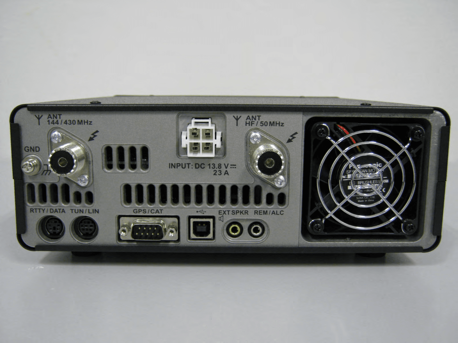
Click to zoom
Application Details
- Equipment Class
- CSR - Scanning Receiver
- Date of Grant
- Nov 10, 2014
- Application Purpose
- Original Equipment
- Date of Application
- Nov 10, 2014
- Equipment Note
- HF / VHF / UHF All Mode Transceiver
- Frequency Range
- 420.00000000 - 470.00000000
- Company
- Yaesu Musen Co., Ltd.
- Country
- Japan
Documents & Files
Document Text
Text extracted from the exhibit documents filed with the FCC. Open a document above to read the original.
Users Manual
HF/VHF/UHF All Mode TrAnsceiVer FT-991 operATing MAnUAl YAESU MUSEN CO., LTD. Tennozu Parkside Building 2-5-8 Higashi-Shinagawa, Shinagawa-ku, Tokyo 140-0002 Japan YAESU USA 6125 Phyllis Drive, Cypress, CA 90630, U.S.A. YAESU UK Unit 12, Sun Valley Business Park, Winnall Close Winchester, Hampshire, SO23 0LB, U.K. Page 1 F T-991 OPERATING MANUAL Table of ConTenTs Table of Contents .........................................................1 Accessories & Options .................................................3 Supplied Accessories ................................................3 Available Options .....................................................4 Adjusting the Clock ..................................................5 Resetting the Microprocessor ...................................5 Installation and Interconnections ...............................6 Antenna Considerations ...........................................6 About Coaxial Cable ................................................6 Grounding .................................................................7 Connection of Antenna and Power Cables ...............8 Connection of Microphone and Headphone .............9 Key, Keyer, and Computer-Driven Keying Interconnections .....................................................10 VL-1000 Linear Amplifier Interconnections ..........11 Interfacing to Other Linear Amplifiers ...................12 Front Panel Controls & Switches .............................13 Display Indications..................................................... 18 Rear Panel ...................................................................21 MH-31A8J Microphone Switches .............................23 Optional FH-2 Switches .............................................24 Basic Operation: Receiving on Amateur Bands ......25 Operation on 60-Meter (5 MHz) Band (U.S. version only) .......................................................................28 CLAR ( Clarifier ) Operation ...................................29 LOCK .....................................................................30 DIMMER ...............................................................30 VFO COLOR .........................................................30 Band Stack Operation .............................................31 C.S ( Custom Switch ) ..............................................31 Convenience Featur es ................................................31 SCOPE ...................................................................32 More Frequency Navigation Techniques ...............33 Receiver Operation ( Front End Block Diagram ) ... 34 AT T ( AttenuAtor ) .................................................. 35 Interference Rejection ...............................................35 IPO ( Intercept Point Optimization ) ........................36 IF Noise Blanker ( NB ) Operation ..........................37 CONTOUR Control Operation ..............................38 IF SHIFT Operation ( SSB/CW/RTTY/PKT Modes ) ....................................................................39 WIDTH ( IF DSP Bandwidth ) Tuning ( SSB/CW/ RTTY/DATA Modes ) .............................................40 NARROW ( NAR ) One-Touch IF Filter Selection .................................................................41 IF NOTCH Filter Operation ( SSB/CW/R TTY/ DATA/AM Modes ) .................................................42 Digital NOTCH Filter ( DNF ) Operation ................43 Digital Noise Reduction ( DNR ) Operation ............43 Tools for Comfortable and Effective Reception ......44 RF Gain ..................................................................44 Audio Peak Filter ...................................................45 AGC ( Automatic Gain Control ) .............................46 Adjustable Receiver Audio Filter ...........................47 SSB/AM Mode Transmission ....................................48 A TU Operation .......................................................50 Using the Automatic Antenna Tuner ........................50 About ATU Operation ............................................51 PArAmetric microphone equAlizer ( SSB/Am/Fm mode ) ...................................................................... 52 Enhancing Transmit Signal Quality .........................52 Using the Speech Processor ( SSB Mode ) ..............54 Adjusting the SSB Transmitted Bandwidth (SSB Mode) .....................................................................55 V oice Memory ( SSB/AM/FM modes: Requires optional DVS-6 and FH-2 ) ................................56 Transmitter Convenience Features ..........................56 VOX (SSB/AM/FM Modes: Automatic TX/RX Switching using Voice Control) .............................58 MONIT OR ( SSB/AM/FM modes ) .........................59 Split-Frequency Operation .....................................60 Setup for Straight Key ( and Straight Key emulation ) Operation ................................................................61 CW Mode Operation .................................................61 Using the Built-in Electronic Keyer .......................62 CW Spotting ( Zero-Beating ) ..................................65 CW Convenience Featur es ........................................65 CW Delay Time Setting .........................................66 Contest Memory Keyer (Using the Optional FH-2 Remote Control Keypad) .......................................67 Basic Operation ......................................................72 Page 2 F T-991 OPERATING MANUAL Table of ConTenTs FM Mode Operation ..................................................72 Repeater Operation .................................................73 Tone Squelch Operation .........................................74 Memory Operation ....................................................75 Convenient Memory functions ...............................75 QMB ( Quick Memory Bank ) .................................75 Standard Mem…
Text truncated - open the document above for the full version.
Users Manual
Page 42FT-991 OPERATING MANUAL inTerferenCe reJeCTion iF notch Filter operAtion ( SSb/cw/rtty/dAtA/AM ModeS ) The IF NOTCH filter is a highly effective system that allows you to slice out an interfering beat note or other carrier signal from inside the receiver passband. 1. Press the F(M-LIST) button, then touch [ NOTCH ] on the LCD to activate the Notch filter. The DSP graphic display will illuminate and the current “null” position of the NOTCH filter will appear in the NOTCH indicator on the display. The MULTI knob functions as the Notch adjustment knob. 2. Rotate the MULTI knob to adjust the “null” position of the Notch filter. 3. To cancel the NOTCH filter, touch [ NOTCH ] on the LCD. The graphic disappears from the NOTCH indicator on the display, confirming that the NOTCH filter is no longer in operation. Advice: Alternate touches of [ NOTCH ] , will switch the NOTCH filter between on and off. Advice: The bandwidth of the NOTCH filter (either narrow or wide) may be adjusted using Menu item “ 114 IF NOTCH WIDTH ”. The factory default setting is “WIDE”. The performance of the IF NOTCH filter is illus- trated in Figure “ A ”, where the effect of rotation of the MULTI knob is depicted. In Figure “ B ” you can see the notching effect of the IF NOTCH filter as you rotate the MULTI knob to eliminate the interfering heterodyne. A B Desired SignalDesired Signal QRM (Heterodyne) QRM (Heterodyne) IF BANDWIDTHIF BANDWIDTH MULTI F(M-LIST) Button Page 43FT-991 OPERATING MANUAL digitAl notch Filter ( dnF ) operAtion The Digital NOTCH Filter (DNF) is an effective beat-canceling filter that can null out a number of interfering beat notes inside the receiver passband. Because this is an Auto-Notch feature, there is no adjustment knob associated with this fil- ter. Advice: If a very strong interfering carrier is encountered, we recommend you first use the IF NOTCH filter, as it is the most ef- fective notching tool in the receiver section. 1. Press the F(M-LIST) button, then touch [ DNF ] on the LCD. The “ DNF ” will appear in the display. To disable the Digital NOTCH Filter, just repeat the above procedure, touching [ DNF ] on the LCD to choose “ OFF ”. The “ DNF ” will turn off, confirming that the Digital NOTCH Filter is not active. digitAl noiSe reduction ( dnr ) operAtion The Digital Noise Reduction (DNR) system is designed to reduce the level of random noise found on the HF and 50 MHz bands, and it is especially effective during SSB operation. By setting the Menu item “ 110 DNR LEVEL ”, any of 15 different noise-reduction algorithms can be selected; each of these algorithms was created for dealing with a different noise profile. You will want to experiment with the DNR system to find the best setting corresponding to the noise cur- rently being experienced. 1. Press the F(M-LIST) button, then touch [ DNR ] on the LCD. The “ DNR ” will appear in the display. To disable the DNR system, just repeat the above proce- dure, touching [ DNR ] on the LCD to choose “ OFF ”. The “ DNR ” will turn off, confirming that the DNR system is not active. inTerferenCe reJeCTion F(M-LIST) Button F(M-LIST) Button Page 44FT-991 OPERATING MANUAL Tools for CoMforTable and effeCTive reCepTion rF gAin The RF Gain control provides manual adjustment of the gain levels for the receiver RF and IF stages, to account for noise and signal strength conditions at the moment. 1. The RF GAIN knob should, initially, be rotated to the fully clockwise position. This is the point of maximum sensitivity. 2. Counter-clockwise rotation of the RF GAIN knob will gradually reduce the system gain. Advice: As the RF GAIN knob is rotated counterclockwise to reduce the gain, the S-meter reading will rise. This indicates that the AGC voltage being applied to the receiver is increasing (this causes a reduction in re- ceiver gain). Rotating the RF GAIN knob control to the fully counter-clockwise position will essentially disable the receiver, as the gain will be greatly reduced. In this case, the S-meter will appear to be “pegged” against the right edge of the analog S-meter scale. quick point: Reception frequently can be optimized by rotating the RF GAIN knob slightly counter-clockwise to the point where the “stationary” meter indication is set just about the same as the incoming noise level. This will reduce the RF gain to find a level of improved signal to noise ratio. The RF Gain control, along with the IPO and the At- tenuator features, all affect the system receiver gain in different ways. The IPO generally should be the first feature engaged when dealing with a high noise level, or a crowded, high-level signal environment. Also, the IPO generally should be the first feature engaged, if the frequency is low enough to allow the preamplifier to be bypassed. Thereafter, the RF Gain and Attenuator features may be employed to provide precise, delicate adjustment of the receiver gain to fully optimize performance. RF GAIN Knob Page 45FT-991 OPERATING MANUAL Tools for CoMforTable and effeCTive reCepTion Audio peAk Filter 1. Press the F(M-LIST) button, then touch [ APF ] on the LCD. The “ APF ” indicator will appear in the DSP display. Advice: When APF is engaged, the peak position of the APF is depicted graphically in the NOTCH indicator on the display. 2. Touch [ AFP ] on the LCD again to disable the APF. Advice: The APF may only be activated while the transceiver is in CW mode. F(M-LIST) Button Page 46FT-991 OPERATING MANUAL Agc ( AutoMAtic gAin control ) The AGC system is designed to help compensate for fading and other propagation effects. The AGC characteristics can be individually set for each operating mode. The basic objective of AGC is to maintain a constant audio output level once a certain minimum threshold of signal strength is achieved. Press the F(M-LIST) button, then touch [ AGC ] on the LCD repeatedly to select the desired receiver-recovery time constant. You will observe the AGC status notation in the AGC column of the Key …
Text truncated - open the document above for the full version.
Attestation Statements
16 October 2014 Federal Communications Commission Authorization and Evaluation Division, 7435 Oakland Mills Road Columbia, MD 21046 USA Re: FT-991 (FCC ID: K6620575X50) Gentlemen: The scanner receiver equipment meets the requirements of the FCC Rules, 15.121(a). Compliance is achieved through the following methods: The scanner receiver in this equipment is incapable of tuning, or readily being altered, by the User to operate within the frequency bands allocated to the Domestic Public Cellular Te l ecommunications Service in Part 22. Blocking of the cellular frequencies is implemented in the firmware of the unit’s main control central processing unit (CPU). Coverage of 824 - 849 MHz and 869 - 894 MHz is completely blocked, since it is done in the microprocessor, and cannot be re-enabled by any user-accessible procedure, including diode, resistor, or jumper changes, nor by connection of any external device such as a personal computer, nor by installation of any “special” enabling semiconductor device. The scanning receiver is designed so that the tuning, control and filtering circuitry is inaccessible. Sincerely, YAESU MUSEN CO., LTD. Kouji Taguchi Engineering Division / Quality Assurance
Cover Letter(s)
Authority to Act as Agent 30 September 2014 American Certification Body, Inc. 6731 Whittier Avenue Suite C110 McLean, VA 22101 To Whom It May Concern: SGS RF Technologies Inc. is authorized to act on our behalf, until otherwise notified, for applications to American Certification Body, Inc. (ACB). We certify that we are not subject to denial of federal benefits, that includes FCC benefits, pursuant to Section 5301 of the Anti-Drug Abuse Act of 1988, 21 U.S.C. 862. Further, no party, as defined in 47 CFR 1.2002 (b), to the application is subject to denial of federal benefits, that includes FCC benefits. Thank you, Agency Agreement Expiration Date: 12 month By: Kouji Taguchi Title: Engineering Division/ Quality Assurance On behalf of: YAESU MUSEN CO., LTD. Telephone: +81-3-6711-4121
Cover Letter(s)
Request for Confidentiality 30 September 2014 Subject: Confidentiality Request for FCC ID: K6620575X50 Pursuant to FCC 47 CRF 0.457(d) and 0.459 and IC RSP-100, Section 10, the applicant requests that a part of the subject FCC application be held confidential. Type of Confidentiality Requested Exhibit Short Term Permanent Block Diagrams Short Term Permanent Internal Photos Short Term Permanent Operation Description (Circuit Description) Short Term Permanent Parts List & Placement/BOM Short Term Permanent Schematics YAESU MUSEN CO., LTD. has spent substantial effort in developing this product and it is one of the first of its kind in industry. Having the subject information easily available to "competition" would negate the advantage they have achieved by developing this product. Not protecting the details of the design will result in financial hardship. Permanent Confidentiality: The applicant requests the exhibits listed above as permanently confidential be permanently withheld from public review due to materials that contain trade secrets and proprietary information not customarily released to the public. Short-Term Confidentiality: The applicant requests the exhibits selected above as short term confidential be withheld from public view for a period of 180 days from the date of the Grant of Equipment Authorization and prior to marketing. This is to avoid premature release of sensitive information prior to marketing or release of the product to the public. Applicant is also aware that they are responsible to notify ACB in the event information regarding the product or the product is made available to the public. ACB will then release the documents listed above for public disclosure pursuant to FCC Public Notice DA 04-1705. NOTE for Industry Canada Applications: The applicant understands that until such time that IC distinguishes between Short Term and Permanent Confidentiality, either type of marked exhibit above will simply be marked Confidential when submitted to IC. Sincerely, By: Kouji Taguchi Engineering Division / Quality Assurance
ID Label/Location Info
FT-991 ID DRAWING YAESU MUSEN CO., LTD. ID and CAUTION drawings CAUTION drawings Label location ID drawing Model:FT-991 FCC ID: K6620575X50 IC: 511B-20575X50 YAESU MUSEN CO., LTD. MADE IN JAPAN Model:FT-991 FCC ID: K6620575X50 IC: 511B-20575X50 YAESU MUSEN CO., LTD. MADE IN JAPAN
Test Report
Issue Date: 23 Oct. 2014 Report No.: ERY1410P23R3 Model: FT-991 SGS RF Technologies Inc. Page 1 of 22 472, Nippa-cho, Kohoku-ku, Yokohama, 223-0057, Japan Telephone: +81+(0)45- 534-0645, FAX: +81+(0)45- 534-0646, Web: http://www.rft.jp TEST REPORT For HF/VHF/UHF All Mode Transceiver In conformity with FCC CFR 47 Part15 Subpart B Model : FT-991 FCC ID : K6620575X50 Test Item : HF/VHF/UHF All Mode Transceiver Report No. : ERY1410P23R3 Issue Date : 23 Oct. 2014 Prepared for YAESU MUSEN CO., LTD. Tennozu Parkside Building 2-5-8 Higashi-Shinagawa, Shinagawa-ku, Tokyo 140-0002 JAPAN Prepared by SGS RF Technologies Inc. 472, Nippa-cho, Kohoku-ku, Yokohama, 223-0057, Japan Telephone: +81+(0)45- 534-0645 FAX: +81+(0)45- 534-0646 Issue Date: 23 Oct. 2014 Report No.: ERY1410P23R3 Model: FT-991 SGS RF Technologies Inc. Page 2 of 22 472, Nippa-cho, Kohoku-ku, Yokohama, 223-0057, Japan Telephone: +81+(0)45- 534-0645, FAX: +81+(0)45- 534-0646, Web: http://www.rft.jp This document is issued by the Company subject to its General Conditions of Service printed overleaf, available on request or accessible at www.sgs.com/terms_and_conditions.htm and, for electronic format documents, subject to Terms and Conditions for Electronic Documents at www.sgs.com/terms_e-document.htm. Attention is drawn to the limitation of liability, indemnification and jurisdiction issues defined therein. Any holder of this document is advised that information contained hereon reflects the Company’s findings at the time of its intervention only and within the limits of Client’s instructions, if any. The Company’s sole responsibility is to its Client and this document does not exonerate parties to a transaction from exercising all their rights and obligations under the transaction documents. This document cannot be reproduced except in full, without prior written approval of the Company. Any unauthorized alteration, forgery or falsification of the content or appearance of this document is unlawful and offenders may be prosecuted to the fullest extent of the law. SGS RF Technologies Inc. is managed to ISO17025 and has the necessary knowledge and test facilities for testing according to the referenced standards. The test results in this report apply only to the sample tested. Issue Date: 23 Oct. 2014 Report No.: ERY1410P23R3 Model: FT-991 SGS RF Technologies Inc. Page 3 of 22 472, Nippa-cho, Kohoku-ku, Yokohama, 223-0057, Japan Telephone: +81+(0)45- 534-0645, FAX: +81+(0)45- 534-0646, Web: http://www.rft.jp Table of contents 1 General information ...................................................................................................................... 4 1.1 Product description ................................................................................................................................................ 4 1.2 Test(s) performed/ Summary of test result ............................................................................................................ 4 1.3 Test facility ............................................................................................................................................................ 5 1.4 Measurement uncertainty ....................................................................................................................................... 5 1.5 Summary of test results .......................................................................................................................................... 6 1.6 Setup of equipment under test (EUT) .................................................................................................................... 6 1.6.1 Test configuration of EUT ............................................................................................................................. 6 1.6.2 Operating condition: ...................................................................................................................................... 6 1.6.3 Setup diagram of tested system ...................................................................................................................... 7 1.7 Equipment modifications ....................................................................................................................................... 7 1.8 Deviation from the standard .................................................................................................................................. 7 2 Test procedure and test data ........................................................................................................ 8 2.1 Radiated emissions ................................................................................................................................................ 8 2.2 Conducted emissions for receiver ........................................................................................................................ 15 2.3 AC power line conducted emissions .................................................................................................................... 17 3 Test setup photographs ............................................................................................................... 21 3.1 Radiated emissions .............................................................................................................................................. 21 3.2 AC power line conducted emissions .................................................................................................................... 21 4 List of utilized test equipment / calibration .............................................................................. 22 History Report No. Date Revisions Issued By ERY1409P22R1 22 Sep. 2014 Initial Issue T.Kato ERY1410P23R3 23 Oct. 2014 Add the chart for radiated emission test (above 1GHz) in 118MHz operating condition. (Sec 2.1) T.Kato Change the comment in test data (Sec 2.2) T.Kato Issue Date: 23 Oct. 2014 Report…
Text truncated - open the document above for the full version.
Test Setup Photos
Issue Date: 23 Oct. 2014 Report No.: ERY1410P23R3 Model: FT-991 SGS RF Technologies Inc. Page 21 of 22 472, Nippa-cho, Kohoku-ku, Yokohama, 223-0057, Japan Telephone: +81+(0)45- 534-0645, FAX: +81+(0)45- 534-0646, Web: http://www.rft.jp 3 Test setup photographs 3.1 Radiated emissions 3.2 AC power line conducted emissions
Contact Information
Applicant
Masatoshi Muraishi(Engineering Division)
Technical Contact
SGS RF Technologies Inc.Kazuyuki Onishi
[email protected]81-45-534-0645
472, Nippa-cho, Kohoku-ku · Yokohama · Japan
Test Firm
SGS Japan Inc. Kitayamata LabTakayuki Okawara
Technical Specifications
| # | Rule Parts | Frequency Range | Power Output |
|---|---|---|---|
| 3 | 15B | 420 MHz - 470 MHz | - |
Other Applications from Yaesu Musen Co., Ltd.
K660E180X10
Dec 01, 2025BLUETOOTH MICROPHONE
Equipment Class
DTS - Digital Transmission System
K6630673Y3D
Aug 01, 2024VHF FM Marine Transceiver
Equipment Class
CXX - Communications Rcvr for use w/ licensed Tx and CBs
K6630653Y3D
Aug 01, 2024VHF FM Marine Transceiver
Equipment Class
CXX - Communications Rcvr for use w/ licensed Tx and CBs
K6630683X30
Jan 10, 2023VHF FM Marine Transceiver
Equipment Class
TNF - Licensed Non-Broadcast Transmitter Held to Face
K6650033X30
Nov 18, 2020Airband Radio Transceiver
Equipment Class
TNF - Licensed Non-Broadcast Transmitter Held to Face