K6620605X20Analog Scanning Receiver
Yaesu Musen Co., Ltd.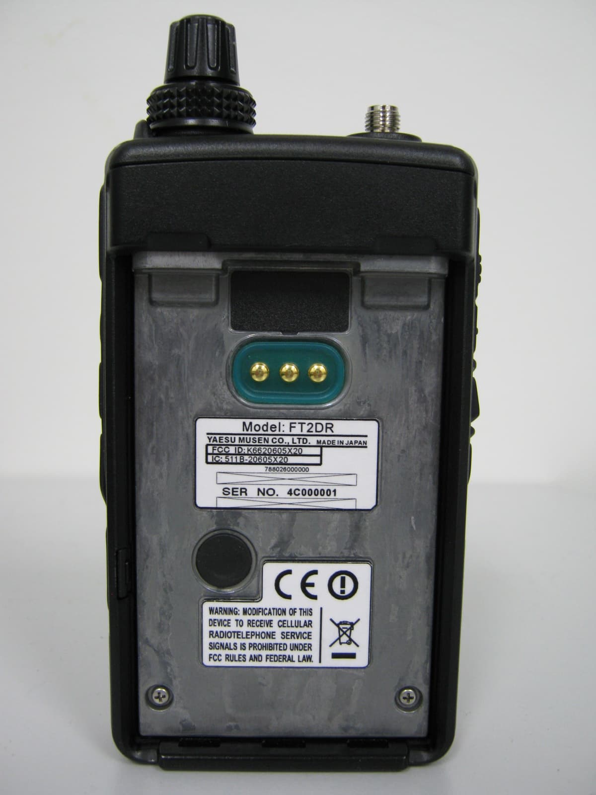
Click to zoom
Application Details
- Equipment Class
- CSR - Scanning Receiver
- Date of Grant
- Mar 05, 2015
- Application Purpose
- Original Equipment
- Date of Application
- Mar 05, 2015
- Equipment Note
- Analog Scanning Receiver
- Frequency Range
- 800.00000000 - 999.00000000
- Company
- Yaesu Musen Co., Ltd.
- Country
- Japan
Documents & Files
Document Text
Text extracted from the exhibit documents filed with the FCC. Open a document above to read the original.
Users Manual
C4FM FDMA 144/430MHz DIGITAL/ANALOG TRANSCEIVER FT2DR Operating Manual Before Using the Transceiver Preparation Basic Operation Using the Memory Appendix 2 Before Using the Transceiver Before Using the Transceiver Introduction Features of the FT2DR m Digital communication (C4FM (Quaternary FSK), FDMA system) ������������������������������xx m Equipped with AMS (Automatic Mode Select) Function ����������������������������������������������xx Automatically selects between 4 modes of transmission according to the signal being received� m External power supply connection ������������������������������������������������������������������������������xx m Simultaneous reception on two different bands, or within the same band (V+V/U+U) ���������������������������������������������������������������������������xx m Independent switching keys for A-band and B-band and TX/BUSY display ���������������xx m Wide-band reception over the range of 500 kHz to 999�900 MHz ������������������������������xx m Waterproof design conforming to IPX5 equivalent, which protects the transceiver from rain and splashes ������������������������������������������������������������������������������������������������xx m Individual side keys �����������������������������������������������������������������������������������������������������xx m 160×160 dot 8-gradation grayscale large LCD screen and touch panel ���������������������xx m WIRES-X connection support ����������������������������������See WIRES-X instruction manual* m Equipped with GM function ����������������������������������See GM function instruction manual* m Large-capacity 1588ch, with twenty-four 100ch memory banks ���������������������������������xx m Display memory tags comprised of up to 20 one-byte characters ������������������������������xx m Convenient reception of preset receiver memory channels ����������������������������������������xx By selecting preset frequencies, you can receive shortwave broadcast, and international VHF radio stations with ease� m A wide variety of scan functions ����������������������������������������������������������������������������������xx m Built-in GPS unit allowing display of your current location and heading information ������������������������������������������������������������������������������������������������������������������xx m Ready for APRS® communication using the world standard 1200/ 9600bps AX25 modem (B band only) ����������������������������������������������������See APRS instruction manual* m High-resolution band scope function to display ± 50 channels �����������������������������������xx m Equipped with the smart navigation function ��������������������������������������������������������������xx m A variety of individual selective calling functions; such as tone squelch (CTCSS) and DCS functions ������������������������������������������������������������������������������������������������������xx m Vibrator to alert you of signal reception, in addition to the audible bell �����������������������xx m New pager function for calling only specific stations ���������������������������������������������������xx m Illumination by white LED for easy viewing of the LCD outdoors ��������������������������������xx m Battery save function to prolong the operating time of the battery ������������������������������xx m Data terminal for communication with external equipment or firmware update ����������xx m Compatible with microSD memory cards ��������������������������������������������������������������������xx m Snapshot function (an optional camera microphone MH-85A11U is required) ����������xx * WIRES-X, GM function and APRS instruction manuals are not included in the product package� They are available and may be downloaded from the Yaesu�com website� 3 Before Using the Transceiver Introduction Using the Touch Screen yCaution when Using the Touch Screen You can perform various function operations simply by gently touching the LCD touch screen � mApplying a LCD protective film to the touch screen may impact the ability of the touch screen to function properly � mRefrain from attempting to manipulate the touch screen with your fingernails or a hard- pointed object such as a pen� Be careful not to apply excessive force when touching the touch screen� Doing so may scratch or damage your touch screen� m The touch screen does not recognize common smartphone operations such as swiping, pinching in, and pinching out� yTouch Screen Upkeep mFor cleaning dust and smudges off your touch screen, turn off the power of your device, and then wipe he touch screen with a dry soft cloth � If the touch screen is very dirty, wet a soft cloth thoroughly, wring out excess water and then wipe the touch screen� mWhen wiping the touch screen, be careful not to apply excessive force or scratch the surface with your fingernails � Screen scratches impair your view of the screen� How to Read This Manual Common explanatory expressions used in this manual are as follows: Press �������������������������������������������������Indicates to simply press a key or switch� Press and hold for over 1 second ������ Indicates to press a key or switch for over 1 second � Touch [F MW] ���������������������������������������������Indicates to simply touch the touch screen� Touch [F MW] for over 1 second ��������������� Indicates touch the touch screen for over 1 second � Select [MODE] �������������������������������������������Indicates to highlights an item� The following symbols are also used in this manual� Caution ���Explains caution to observe during operation� Tip ���Explains operating suggestions or useful tips� 4 Before Using the Transceiver Safety Precautions (Be Sure to Read) Be sure to read the safety precautions to use this product safely. We are not liable for failures and other problems caused due to misuse or use of this product by you or a third party as well as the damages caused through use of this product by you or a thi…
Text truncated - open the document above for the full version.
Users Manual
11 Before Using the Transceiver Names and Functions of Controls Touch Screen Display メモリー書き込み中!A1 ① ② ③ ④ ⑦⑪ ⑫ ⑬ ⑤ ⑥ ④ ⑤ ⑥ ⑧ ⑭ ⑬ ⑭ ⑨⑩ ⑮ ⑩ ① This is the A-band display area� ② This is the B-band display area � ③ Displays touch keys� ④ Displays mode� In VFO mode, “VFO” is displayed� In Memory mode, “MR” and the channel number are displayed� ⑤ Gauge displays the sound volume level� ⑥ Displays the icon of the transmission output, the S meter and the PO meter � S meter: Displays the radio wave strength in 9 steps� PO meter: Displays the transmission power level in 4 steps � H I: High power (5W) L 3: LOW 3 power (2�5W) L 2: LOW 2 power (1W) L 1: LOW 1 power (0�1W) ⑦ Displays the time � ⑧ Displays a shift direction during repeater operation ( see page xx)� -: Minus shift +: Plus shift @: Split operation ⑨ lights up when the Mute function is active ( see page xx)� ⑩ Displays the frequency� ⑪ Displays icon types � : Lights up when the APO function is active ( see page xx)� : Lights up when the DTMF function is enabled ( see page xx)� : Lights up when GPS is acquired ( see page xx)� : Lights up when a microSD memory card is inserted ( see page xx)� : Lights up when using a microSD memory card ( see page xx)� ⑫ The battery condition is displayed in 8 steps� : Full battery power : Battery is depleted� Charge battery� : (When blinking) Charge battery immediately� ⑬ Displays squelch type ( see page xx) TN: Lights up when the tone encoder function is enabled� TSQ: Lights up when the tone squelch function is enabled� DCS: Lights up when the DCS function is enabled� RTN: Lights up when the reverse tone function is enabled� JR: Lights up when the JR idle signal squelch function is enabled� PR: Lights up when the idle signal squelch function is enabled� PAG: Lights up when the pager is enabled� Displays the APRS baud rate ( APRS function Instruction manual)� ⑭ Displays operation mode� FM: FM (Analog) mode : Auto mode (automatic switching among Analog AM, Analog FM, and Digital) *The display of the “FM” portion differs according to the selected mode � DN: Wide digital mode (digital mode using C4FM modulation) VW: Wide digital mode (high-quality digital communication) ⑮ b appears when the bell function is active ( see page xx)� 12 Before Using the Transceiver Names and Functions of Controls yDual Band Screen A-band and B-band are displayed in a top-down fashion � メモリー書き込み中!A1 • Touching [F MW] displays the function menu screen� • Touching [TX DN] enables for the communication mode to be fixed on the transmission side� • Touching [MODE] switches between Analog and Digital� yBand Scope Screen When the band scope operation is enabled, the display is as follows� Reference You can change the number of band scope channels by selecting [DISPLAY] → [4 BAND SCOPE] in Set mode� You can select 17 channels, 35 channels or 71 channels� yFunction Menu Screen Touching [F MW] displays the function menu screen � MENU DISPLAY 2'!A7723TOP画面プリセットレシーバー!A1 TOP画面AF-DUAL表示'!A1Band Scope'!A1 FUNCTION!A389APRS Message list1'!A1APRS Station list1'!A1 13 Before Using the Transceiver Names and Functions of Controls yBACKTRACK Screen Pressing the key displays the BACKTRACK screen� • The compass setting is displayed to the upper left of the compass icon � “H-UP” is displayed when the direction in which you are heading is set to always facing up, whereas “N-UP” is displayed when North is set to always facing up � In the Set mode option [DISPLAY] → [3 COMPASS], you can change the compass setting� • Upon retrieval of the registered position information, the distance from the current position displays to the upper right of the compass icon � • Touching [YR] displays the position of the received friend station displays on the compass icon (only when the signal carries the position information)� • Touching [MY] displays your heading direction on the compass icon� • Touching [MEMORY] switches to the mode for registering the current position information� • Touching [★] displays the position information registered with the “★” tag� When touching while flashing, the position information displayed on the compass icon is stored in the memory with a “★” tag� • Touching [L1] displays the position information registered with the “L1” tag� When touching while flashing, the position information displayed on the compass icon is stored in the memory with an “L1” tag � • Touching [L2] displays the position information registered with the “L2” tag� When touching while flashing, the position information displayed on the compass icon is stored in the memory with an “L2” tag � 14 Before Using the Transceiver Names and Functions of Controls Entering Letters The keyboard screen appears for inputting letters such as your call sign or a memory channel tag � yNumber & Symbol Input Screen • Touch [ABC] to display the alphabet input screen� • Touching [123] switches the key to [#&%] and displays the symbol input screen� Touching each time switches between the number input screen and the symbol input screen � • Touch [ ] [] to move the cursor to left/right in the text input area� yAlphabet Input Screen • Touching [ABC] each time switches between upper case letters and lower case letters � 15 Preparation Preparation Attaching the Supplied Accessories Installing the Antenna 1 Align the bottom side of the antenna with the antenna terminal on the transceiver� Caution Be sure to hold the thick base of the antenna when installing it 2 Turn the antenna clockwise until it is secured� Cautions yDo not hold the upper part of the antenna when installing or removing it� To do so, the wire inside the antenna may break� yDo not transmit without installing the antenna� The transmitter circuit can be damaged� yWhen using an antenna other than the supplied one or any other external antenna, ensure that its SWR is adjusted to 1�5 or lower� Attaching the Accessory Belt Clip/Protective Cap Attaching the Protective Cap If you do not use the belt clip, attach the protective cap to the belt c…
Text truncated - open the document above for the full version.
Users Manual
21 Preparation Preparing the Battery Pack/External Power Supply Connecting an External Power Supply for Use in Vehicle The optional external power supply adapter with a cigarette lighter plug (SDD-13) allows the transceiver to be used in a vehicle� 1 Turn off the transceiver� 2 Insert the plug of the external power supply adapter with a cigarette lighter plug (SDD-13) in the EXT DC IN jack of the transceiver � 3 Insert the cigarette lighter plug of the external power supply adapter in the cigarette lighter socket of the vehicle� Cautions yThe SDD-13 is compatible with a 12 V DC cigarette lighter socket� Do not connect the SDD-13 to the 24 V DC cigarette lighter socket� yUse the transceiver at the minimum required transmission power level to prevent overheating� yDo not continue transmission for a prolonged period of time� The transceiver may overheat, resulting in malfunction or burns� yIf you operate the transceiver for 7 hours or longer, it is recommended that you remove the battery pack and install the optional battery case (FBA-39)� yRecharging the fully-charged battery pack repeatedly can shorten its service life� Be extremely careful not to do so when you operate the transceiver when using an external power supply� yWhile charging the battery pack, protect the transceiver from water� yCharge the battery pack in a place where the ambient temperature is +5 °C to +35 °C (+41 °F to +95 °F). yIf the terminal or electrode of the battery pack is dirty, the transceiver can malfunction due to poor contact, resulting in overheating or rupture� If the terminal or electrode gets dirty, clean it using a dry cloth or cotton swab� Tips • The battery pack can be charged within approximately 8 hours using the external power supply (approximately 8 hours to charge the optional battery pack FNB-102LI)� If the battery pack is charged with the transceiver turned on, the charging time increases slightly� • When the battery pack has been fully charged, charging stops automatically� • The external power supply can be used with the battery case installed� • If you connect the transceiver to the external power supply with the transceiver turned off, “CONNECTED TO EXTERNAL POWER” appears on the LCD, and about 20 seconds later “BATTERY NOT INST ALLED” appears� To cigarette lighter socket of vehicle EXT DC IN jack External power supply adapter with a cigarette lighter plug SDD-13(optional) T�B�D� 22 Preparation Preparing the Battery Pack/External Power Supply Connecting to an External Power Supply Using a Power Cable The optional power cable (E-DC-6) allows the transceiver to be connected to an external power supply � 1 Turn off the transceiver� 2 Connect the optional external power supply cable (E-DC-6) to an external power supply � Remarks • Connect the red/black wire or white/red wire to the positive (+) terminal of the external power supply and the black wire to the negative (−) terminal. • Set the voltage of the external power supply to 12 to 14 V� 3 Insert the plug of the external power supply in the EXT DC IN jack of the transceiver� Cautions yWhen you use the transceiver with the external power supply cable (E-DC-6) connected to an external power supply, pay attention to the following: • The power supply voltage must be between 12 V and 14 V� If the voltage exceeds 14 V, the high voltage protection function is activated to disable high-power transmission� L3 (2�5 W) is selected automatically to reduce the transmission power� If the voltage exceeds 16 V, malfunctions such as damage to the electric circuits of the transceiver may result � Take extra care� • Connect the red/black wire or white/black wire of the external power supply cable (E-DC-6) to the positive (+) terminal of the external power supply and the black wire to the negative (−) terminal. • Use an external power supply having sufficient current capacity (3 A or more)� • If the transceiver is used with supplied antenna connected, the external power supply can malfunction, resulting in a failure � If you use an external power supply, remove the supplied antenna and connect an external antenna� Place the external power supply sufficiently away from the transceiver� yUse the transceiver at the minimum required transmission power level to prevent overheating� yDo not continue transmission for a prolonged period� The transceiver may overheat, resulting in malfunction or burn� yIf you operate the transceiver for 7 hours or longer, it is recommended that you remove the battery pack and install the optional battery case (FBA-39)� yRecharging the fully-charged battery pack repeatedly can shorten its service life� Be extremely careful not to do so when you operate the transceiver using an external power supply� yWhile charging the battery pack, protect the transceiver from water� yCharge the battery pack in a place where the ambient temperature is +5 °C to +35 °C (+41 °F to +95 °F). yIf the terminal or electrode of the battery case is dirty, the transceiver may malfunction due to poor contact, resulting in overheating or rupture� If the terminal or electrode gets dirty, clean it using a dry cloth or cotton swab� Connect the external antenna. External power supply External power supply cable E-DC-6 (optional) T�B�D� 23 Preparation Preparing the Battery Pack/External Power Supply Tips • The battery pack can be charged within approximately 8 hours using the external power supply (approximately 8 hours to charge the optional battery pack FNB-102LI) � If the battery pack is charged with the transceiver turned on, the charging time increases slightly� • The external power supply can be used with the battery case installed� If you connect the transceiver to the external power supply with it turned off, “CONNECTED TO EXTERNAL POWER” appears on the LCD, and about 20 seconds later, “BATTERY NOT INST ALLED” appears� 24 Preparation Using a microSD Memory Card Using a microSD memory card with the transceiver allows the following functions� • Backing up information …
Text truncated - open the document above for the full version.
Users Manual
31 Basic Operation Performing Communication Tips • On A-band, you can transmit and receive using the 144 MHz and 430 MHz Amateur radio bands� • On B-band, you can transmit and receive using the 144 MHz and 430 MHz Amateur radio bands� In addition, the frequencies on the chart below can be received on A-band and B-band� Chart of A-band and B-band reception frequencies A-bandB-band 1.8MHz - 30MHz (SW band) 30MHz - 76MHz (50 MHz band) 108MHz - 137MHz (AIR band) 137MHz - 174MHz (144 MHz band) 174MHz - 222MHz 222MHz - 420MHz (INFO band (1)) 420MHz - 470MHz (430 MHz band) 470MHz - 770MHz 770MHz - 999MHz (INFO band (2)) 108MHz - 137MHz (AIR band) 137MHz - 174MHz (144 MHz band) 174MHz - 222MHz 222MHz - 420MHz (INFO band (1)) 420MHz - 470MHz (430 MHz band) 470MHz - 580MHz — — — — — — 76MHz - 108MHz (FM BC Band) — — 0.5MHz - 1.8MHz (AM BC Band) — — • A-band and B-band can be received at the same time� You can receive Amateur radio frequency while listening to the AIR band, or receive two Amateur radio frequencies on the same frequency band at the same time (V+V/U+U: Dual frequency reception on the same band)� 32 Basic Operation Performing Communication Selecting a Frequency Band You can select a frequency band to use for the A-band and B-band separately� The frequency band can be selected by following the steps below � 1 Press to select A-band� メモリー書き込み中!A1 2 Touch to select your desired frequency band� MENU DISPLAY 2'!A7723TOP画面プリセットレシーバー!A1 TOP画面AF-DUAL表示'!A1Band Scope'!A1 FUNCTION!A389APRS Message list1'!A1APRS Station list1'!A1 Available frequency bands differ depending on the band� The following frequency bands can be used for A-band and B-band� yFrequency band on A-band Short Wave Band50 MHz bandFM BC BandAIR band144 MHz band 174MHz to 222MHz Information radio band (1) 430 MHz band 470MHz to 770MHz Information radio band (2) AM BC Band yFrequency band on B-band AIR band144MHz band174MHz to 222MHz Information radio band (1) 430MHz band 470MHz to 580MHz Caution Digital communication can be performed only on the A-band� Digital communication cannot be performed on the B-band� T�B�D� T�B�D� 33 Basic Operation Performing Communication Tips • The frequency settings from the factory are: A-band: 145�000 MHz B-band: 433�000 MHz • In the default, Auto mode is set so that the transceiver can be automatically switched to the optimal reception mode for the frequency bands� Press and hold for over 1 second to switch the transceiver to Set mode, then touch, [TX/RX] → [1 MODE] → [3 RX MODE] to change mode ( see page xx)� • For the relations between frequency bands and reception frequencies, see the table on page xx� • You can also recall the home channel of each frequency band by touching [F MW] followed by [HOME] ( see page xx)� Tuning in to a Frequency Tune in to your desired frequency using either of the following methods: yRotating the DIAL to tune in to your desired frequency 1 Press the key to switch the transceiver to VFO mode� 2 Rotate the DIAL to tune in to your desired frequency� Rotate clockwise: The frequency increases� Rotate counterclockwise: The frequency decreases � Tip By touching [F MW] and rotating the DIAL, you can tune in to the desired frequency in steps of 1 MHz� yEntering your desired frequency directly using the numeric keys 1 Press the key to switch the transceiver to VFO mode� 2 Touch the frequency displayed on the LCD� The numeric keypad appears� メモリー書き込み中!A1 34 Basic Operation Performing Communication 3 Enter the frequency using the numeric keys� Example: To input 145�520 MHz [1] → [4] → [5] → [5] → [2] → [ENT] Example: To input 430�000 MHz [4] → [3] → [ENT] Tips • In factory settings, Auto Step mode is set such that the transceiver is automatically switched to the optimal frequency steps for the reception frequency� You can also change frequency steps manually rotating the DIAL ( see page xx)� • If you enter a wrong digit when entering a frequency using numeric keys, you can cancel it by pressing � • In factory settings, turning the DIAL further beyond the selected frequency band causes the transceiver to switch to another frequency band� To prevent this from happening, press and hold for over 1 second to switch to Set mode, then touch [CONFIG] → [21 VFO MODE], and select “BAND” for repeatedly showing frequencies on the same frequency band� Selecting Communication Mode yUsing AMS This transceiver is equipped with AMS (Automatic Mode Select) which automatically selects between 4 modes of transmission to fit the signal being received � Because the transmission is automatically adjusted to that of the other station, not only C4FM digital signals, but analog signals are also recognized automatically � To utilize the AMS function, repeatedly touch [MODE] on the LCD until “ ” appears� After receiving the signal, “DN” of “ ” will be changed according to the received signal � メモリー書き込み中!A1 Example of when AMS is displayed yFixing the Communication Mode To fix the communication mode for operation, touch [MODE] on the LCD to switch the communication mode � Touching [MODE] on the LCD each time toggles the communication mode as follows� 35 Basic Operation Performing Communication [ (AMS)] → [DN (V/D mode)] → [VW (FR mode)] → [FM (analog)] Operation modeIconDescription of Modes AMS (Automatic Mode Select) Transmission mode is automatically selected from 4 types according to the signal received� (“DN” part differs depending on the received signal�) The AMS function operation can be changed with the Set mode setting ( see page xx)� V/D Mode (Voice/Data simultaneous transmission mode) DNCalls are less prone to interruptions due to detection and correction of voice signals during digital voice signal transmission � This is the standard mode for C4FM FDMA Digital� Voice FR Mode (Voice Full Rate Mode) VWHigh speed data communication using entire 12�5 kHz band� Enables high-quality voice communication� Data FR Mode (High Speed Data Communication Mode) DWDigital voice data transmission using the en…
Text truncated - open the document above for the full version.
Attestation Statements
March 4, 2015 Federal Communications Commission Authorization and Evaluation Division, 7435 Oakland Mills Road Columbia, MD 21046, USA Re: FT2DR (FCC ID: K6620605X20) Gentlemen: The FT2DR FCC ID: K6620605X20 final device to be certified will be restricted to transmit only within the amateur bands 144 - 148 MHz and 420 - 450 MHz. Sincerely, YAESU MUSEN CO., LTD. Kouji Taguchi Engineering Division / Quality Assurance
Attestation Statements
January 19, 2015 Federal Communications Commission Authorization and Evaluation Division, 7435 Oakland Mills Road Columbia, MD 21046, USA Re: FT2DR (FCC ID: K6620605X20) Gentlemen: A. Part 15.19 & 15.21 Compliance Statement Drawing: B. Part 15.19 & 15.21 Compliance Statement Drawing Location: IN OPERATION MANUAL (location on inside back cover) Sincerely, YAESU MUSEN CO., LTD. Kouji Taguchi Engineering Division / Quality Assurance 1. Changes or modifications to this device not expressly approved YAESU MUSEN could void the user’s authorization to operate this device. 2. This device complies with part 15 of the FCC rules. Operation is subject to the following two conditions; (1) This device may not cause harmful interference, and (2) this device must accept any interference including interference that may cause undesired operation. 3. The scanning receiver in this equipment is incapable of tuning, or readily being altered, by the user to operate within the frequency bands allocated to the Domestic public Cellular Telecommunications Service in the Part 22.
Attestation Statements
January 19, 2015 Federal Communications Commission Authorization and Evaluation Division, 7435 Oakland Mills Road Columbia, MD 21046 USA Re: FT2DR (FCC ID: K6620605X20) Gentlemen: The scanner receiver equipment meets the requirements of the FCC Rules, 15.121 (a). Compliance is achieved through the following methods: The scanner receiver in this equipment is incapable of tuning, or readily being altered, by the User to operate within the frequency bands allocated to the Domestic Public Cellular Telecommunications Service in Part 22. Blocking of the cellular frequencies is implemented in the firmware of the unit’s main control central processing unit (CPU). Coverage of 824 - 849 MHz and 869 - 894 MHz is completely blocked, since it is done in the microprocessor, and cannot be re-enabled by any user-accessible procedure, including diode, resistor, or jumper changes, nor by connection of any external device such as a personal computer, nor by installation of any “special” enabling semiconductor device. The scanning receiver is designed so that the tuning, control and filtering circuitry is inaccessible. Sincerely, YAESU MUSEN CO., LTD. Kouji Taguchi Engineering Division / Quality Assurance
Cover Letter(s)
January 19, 2015 Federal Communications Commission EQUIPMENT APPROVAL SERVICES P. O. Box 358315 Pittsburgh, PA 15251-5315 Attention: Authorization and Evaluation Division Reference: FT2DR (FCC ID: K6620605X20) Pursuant to Sections 0.457 (d) (1) (ii) and 0.459 of the Commission’s Rules, the Applicant hereby requires confidential treatment of some of the information accompanying this Application, as listed below: Confidential ・ Block Diagram ・ Schematics ・ Operation Description (Circuit Description) ・ Parts List ・ Internal Photos Short-Term Confidential ・ Operating Manual ・ External Photos These materials contain trade secrets and proprietary information not customarily released to the public. The public disclosure of these matters might be harmful to the Applicant and provide unjustified benefits to its competitors. The Applicant understands that pursuant to Rule 0.457 (d) (1) (ii), disclosure of the Application and all accompanying documentation will not be made before the date of Grant for this Application. Sincerely, YAESU MUSEN CO., LTD. Kouji Taguchi Engineering Division / Quality Assurance
ID Label/Location Info
FT2DR ID DRAWING YAESU MUSEN CO., LTD. ID and CAUTION drawings CAUTION drawings Label location ID drawing Model: Title: Model: FT2DR K6620605X20 511B-20605X20 YAESU MUSEN CO., LTD. MADE IN JAPAN 788026000000 Model: FT2DR K6620605X20 511B-20605X20 YAESU MUSEN CO., LTD. MADE IN JAPAN 788026000000 2:1 1:1 1:1 2:1
Test Report
FCC PART 15 SCANNING RECEIVER Applicant YAESU MUSEN CO., LTD. Address TENNOZU PARKSIDE BUILDING 2-5-8 HIGASHI-SHINAGAWA, SHINAGAWA-KU, TOKYO 140-0002 JAPAN FCC ID: K6620605X20 Model Number FT2DR Product Description ANALOGUE SCANNING RECEIVER Date Sample Received 1/29/2015 Date Tested 2/18/2015 Tested By CHRISTIAN PAWLAK Approved By SID SANDERS Test Results PASS FAIL Report Number Version Number Description Issue Date 233AUT15TestReport.docx Rev.1 Initial Issue 3/5/2015 THE ATTACHED REPORT SHALL NOT BE REPRODUCED EXCEPT IN FULL WITHOUT THE WRITTEN APPROVAL OF TIMCO ENGINEERING, INC. 849 NW State Road 45 Newberry, Fl 32669 USA Phone: 888.472.2424 or 352.472.5500 Fax: 352.472.2030 Email: [email protected] Website: www.timcoengr.com APPLICANT: YAESU MUSEN CO., LTD. FCC ID: K6620605X20 REPORT #: Y\YAESU\233AUT15\233AUT15TestReport.docx Page 2 of 22 TABLE OF CONTENTS GENERAL REMARKS .................................................................................................... 3 REPORT SUMMARY PAGE ............................................................................................. 4 GENERAL INFORMATION ............................................................................................. 5 TEST PROCEDURE ...................................................................................................... 6 RADIATED SPURIOUS EMISSIONS ................................................................................ 7 Test Data: Plots Low End of Band ......................................................................... 8 30–200 MHz PLOT ............................................................................................... 8 Test Data: Plots Low End of Band ......................................................................... 9 200-1000 MHz PLOT .................................................................................…
Text truncated - open the document above for the full version.
Contact Information
Applicant
Masatoshi Muraishi(Engineering Division)
Technical Contact
Timco Engineering, Inc.Christian Pawlak
[email protected]888-472-2424
849 NW State Road 45 · Newberry, Florida · United States
Non-Technical Contact
Timco Engineering, Inc.Sharon Hoffman
[email protected]888-472-2424
Test Firm
Timco Engineering, Inc.Bruno Clavier
Technical Specifications
| # | Rule Parts | Frequency Range | Power Output |
|---|---|---|---|
| 12 | 15B | 800 MHz - 999 MHz | - |
Other Applications from Yaesu Musen Co., Ltd.
K660E180X10
Dec 01, 2025BLUETOOTH MICROPHONE
Equipment Class
DTS - Digital Transmission System
K6630673Y3D
Aug 01, 2024VHF FM Marine Transceiver
Equipment Class
CXX - Communications Rcvr for use w/ licensed Tx and CBs
K6630653Y3D
Aug 01, 2024VHF FM Marine Transceiver
Equipment Class
CXX - Communications Rcvr for use w/ licensed Tx and CBs
K6630683X30
Jan 10, 2023VHF FM Marine Transceiver
Equipment Class
TNF - Licensed Non-Broadcast Transmitter Held to Face
K6650033X30
Nov 18, 2020Airband Radio Transceiver
Equipment Class
TNF - Licensed Non-Broadcast Transmitter Held to Face