K6620761X50Scanning Receiver
Yaesu Musen Co., Ltd.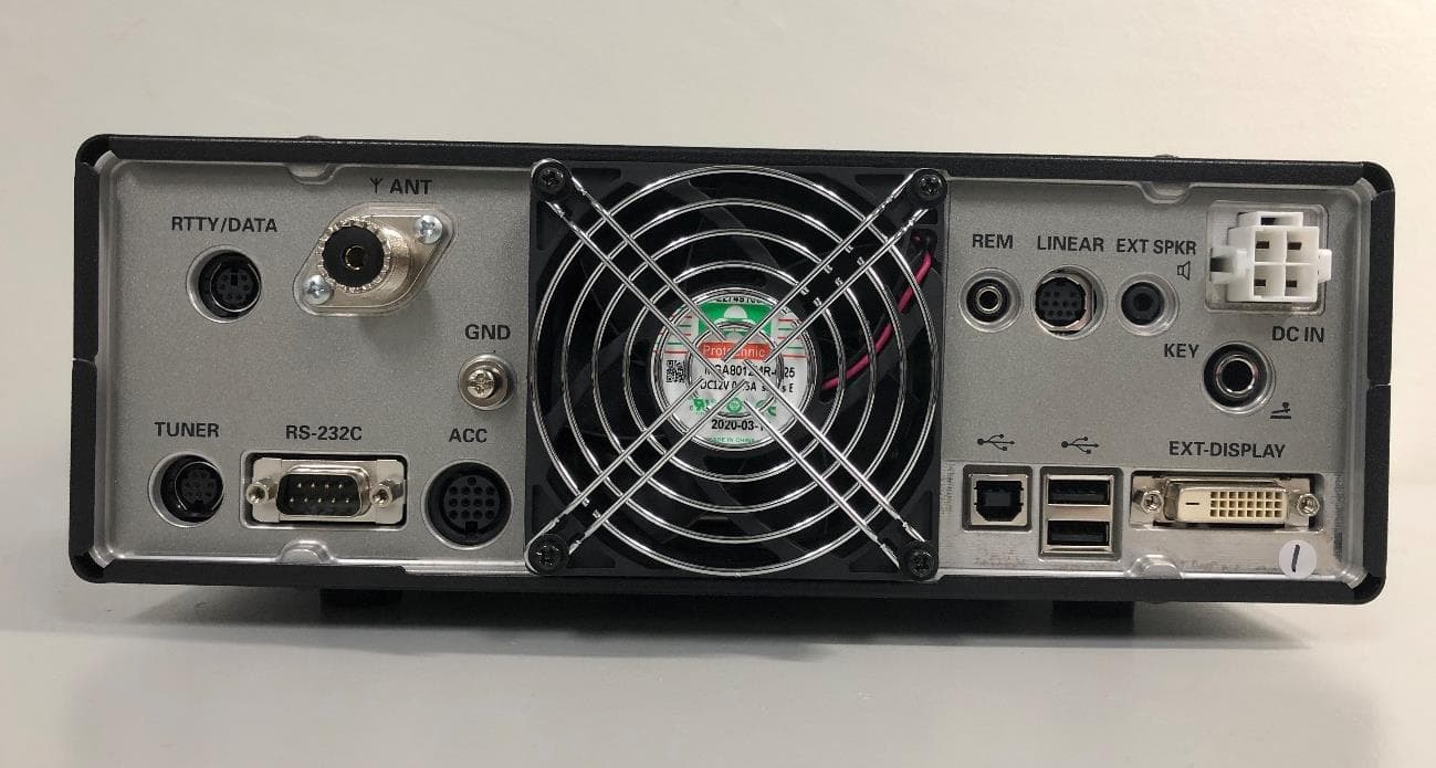
Click to zoom
Application Details
- Equipment Class
- CSR - Scanning Receiver
- Date of Grant
- Nov 03, 2020
- Application Purpose
- Original Equipment
- Date of Application
- Oct 29, 2020
- Equipment Note
- Scanning Receiver
- Frequency Range
- 0.03000000 - 75.00000000
- Company
- Yaesu Musen Co., Ltd.
- Country
- Japan
Documents & Files
Document Text
Text extracted from the exhibit documents filed with the FCC. Open a document above to read the original.
Users Manual
Operation Manual Table of Contents Accessories & options ....................................1 Supplied Accessories ........................................1 Available options ...............................................1 ....................2 Antenna Considerations ....................................2 Connection of Antenna and Power Cables ........2 Connection of Microphone, Headphone, Key, Keyer and FH-2 .................................................3 Front panel controls & Switches .....................4 Display indications ........................................10 Rear Panel....................................................11 Basic Operation ............................................13 Turning the Transceiver ..................................13 ON and OFF ....................................................13 ...................................................13 Audio Volume Level .........................................13 Operating Band Selection ...............................13 Operating Mode Select ....................................13 Setting the Operating Frequency ....................14 .......................................15 RF Power output control ..................................15 DIAL knob Lock ...............................................15 Receiver Accessories ...................................16 ..............................16 RF Gain ...........................................................16 AGC ( ..........................16 CW Decode .....................................................17 Audio Peak Filter .............................................17 ............................17 .......................................17 Interference Rejection ..................................18 ...................18 Contour Control Operation ..............................18 IF SHIFT Operation .........................................19 WIDTH Tuning .................................................19 ..............................................19 IF NOTCH Filter Operation ..............................19 DNR Operation ................................................20 .........................................20 Operation .........................................................20 Transmitter Operation ...................................21 Transmission ...................................................21 Changing the ..................................................21 transmission meter ..........................................21 .....................................21 Speech Processor ...........................................21 Monitor ............................................................21 VOX .................................................................22 Split-Frequency Operation ..............................22 CW Mode Operation .....................................23 Setup for Straight Key Operation ....................23 Using the Built-in Electronic Keyer ..................24 FM Mode Operation......................................25 Repeater Operation .........................................25 Tone Squelch Operation ..................................25 SCOPE .........................................................26 Scope function setting .....................................26 Memory Operation ........................................28 Memory Storage ..............................................28 Memory Channel Recall ..................................28 Erasing Memory Channel Date .......................29 ............................29 Setting Menu ................................................30 Using Menu .....................................................30 Resetting the Microprocessor .......................35 .................................................36 General ............................................................36 Transmitter ......................................................36 Receiver ..........................................................37 1 Accessories & options Supplied Accessories SSM-75E DC Power Cord 1/4-inch 3-contact Plug Operation Manual Available options Reference Microphone M-1 Dual Element Microphone M-100 Ultra-High-Fidelity Desktop Microphone MD-200A8X Desktop Microphone MD-100A8X Lightweight Stereo Headphone YH-77STA External Automatic Antenna Tuner FC-40 Remote Control Keypad FH-2 2 Installation and interconnections Antenna Considerations The FTDX10 is designed for 50 Ohm resistive impedance at the amateur operating frequencies. chosen operation and bands. Construct the antenna and coaxial cable, or use a suitable antenna tuner, to maintain the impedance pre- sented to the FTDX10 antenna connector for an SWR of 1.5 or less. Careful preparation of the antenna and/or tuner will permit maximum performance and protect the transceiver from damage. High voltages may be present on the antenna; install it so it will not be easily touched when in operation. Connection of Antenna and Power Cables Please follow the outline in the illustration regarding the proper connection of antenna coaxial cables, as well as the DC power cable. RED Antenna FUSE: 25A DC power cord (supplied) To prevent damage from lightning, atmospheric electricity, electrical shock etc., please provide a good earth ground. Use a short, thick, braided cable to connect your station equipment to the buried ground rod (or alternative earth ground system). 3 Connection of Microphone, Headphone, Key, Keyer and FH-2 DOWN UP +5V MIC GND MIC PTT GND FAST FH-2 4 Front panel controls & Switches ON/OFF Switch Press and hold in this switch for one second to turn the transceiver on. Similarly, press and hold in this TUNE Antenna Tuner. the antenna tuner. Press the [TUNE] key for about 1 second to start “automatic tuning”. Since the transceiver transmits automati- cally during automatic tuning, make sure to connect an antenna or dummy load before tuning up. When the antenna or dummy load does not match the impedance, “HI-SWR” w…
Text truncated - open the document above for the full version.
Users Manual
19 IF SHIFT Operation higher or lower, without changing the pitch of the incoming signal, and thus reduces or eliminates interference. Because the tuned carrier frequen- cy is not varied, there is no need to re-tune the operating frequency to eliminate the interference. The total passband tuning range for the IF SHIFT system is ±1.2 kHz. Rotate the [SHIFT] knob to the left or right to re- duce the interference. The display will show the shift value of the IF SHIFT for 2 seconds whenever the [SHIFT] knob is turned. Press and hold the SHIFT knob to reset the IF SHIFT setting to “0 Hz”. SHIFT knob WIDTH Tuning The IF WIDTH tuning system allows you to vary the width of the DSP IF passband, to reduce or eliminate interference. Moreover, the bandwidth may actually be expand- ed from its default setting, should you wish to en- on the band is low. Rotate the [WIDTH] knob counter-clockwise to narrow the bandwidth and reduce interference. To increase the bandwidth, rotate the knob clockwise. The display will show the bandwidth of the IF SHIFT, while tuning the [WIDTH] knob. Press and hold the [SHIFT] knob to restore the WIDTH setting to factory default. WIDTH knob ATT (Attenuator) When extremely strong local signals or high noise degrades reception, you can use the [ATT] button to insert 6, 12, or 18dB of RF attenuation in front 1. Touch [ATT]. 2. Touch desired attenuation level, per the chart below. OFF 6dB The incoming signal power is reduced 12dB The incoming signal power is reduced 18dB The incoming signal power is reduced If the noise level is high or the received signal is extremely strong, the incoming signal level can be suppressed with the IPO/ATT settings. If the S-meter fluctuates S-3 or more in the noise level, or the received signal is extremely strong and it causes a high Smeter indication Since IPO does not only attenuate the incoming signal, but also improves the cross modulation characteristic, try to activate the the ATT. In this way, you can attenuate the IF NOTCH Filter Operation that allows cutting out an interfering beat note or other carrier signal from inside the receiver pass- band. 1. Rotate the [NOTCH] knob to adjust the “null” Press and hold the [NOTCH] key to restore the IF NOTCH setting to the factory default. [NOTCH] key. NOTCH key 20 DNR Operation - signed to reduce the level of random noise found on the HF and 50 MHz bands, and it is especially 1. Press the [DNR] key. 2. Press and hold the [DNR] key, then rotate the [FUNC] knob to set the noise reduction algo- rithms. 3. To exit from DNR operation, press the [DNR] key. DNR key Noise Blanker (NB) Operation The FTDX10 includes an effective IF Noise Blanker, which can significantly reduce noise caused by automotive ignition systems. 1. Press the [NB] key. 2. Press and hold the [NB] key, then rotate the [FUNC] knob to set the noise blanker level. 3. To end Noise Blanker operation, press the [NB] key once more. NB key other types of interference. Adjusting the Noise Attenuation 1. Press the [FUNC] knob. 2. - 3. Rotate the [FUNC] knob to set the noise at- 4. Press the [FUNC] knob to save the new set- ting. 21 Transmission 1. Press the microphone PTT switch to begin transmitting. The “TX” indicator will light up in the LED indicators Release the PTT switch to return to receive mode. When transmitting in the AM mode, set a maximum 2. Then touch the meter area on the display to select the “ALC” meter. 3. Close the PTT switch, and speak into the mi- crophone in a normal voice level. In the SSB mode Adjust the MIC gain so that the ALC meter stays within the ALC zone of the meter on voice peaks. In the AM mode When transmitting in the AM mode, adjust the MIC gain so that the ALC meter does not de- Changing the transmission meter Touch the meter area and the meter selection screen will be displayed, so touch the desired meter. POIndicates the average power output level. COMPIndicates the speech compression level. ALCIndicates the relative ALC voltage. VDD ID current. SWRIndicates the Standing Wave Ratio. TOT (Time Out Timer) - mitter after continuously transmitting for the pro- grammed time. 1. Press the [FUNC] knob. 2. - 3. Rotate the [FUNC] knob to select the TOT 4. Press the [FUNC] knob to save the new set- ting. Transmitter Operation Speech Processor The FTDX10 Speech Processor is designed to increase “talk power” by increasing the average power output (via a sophisticated compression 1. Press the [FUNC] knob. 2. Touch [PROC]. Speech Processor feature is activated. 3. Then touch the meter area on the display to select the “COMP” meter. 4. Press the PTT switch on the microphone, and speak into the microphone in a normal voice level. To adjust the Compression level: 1. Press the [FUNC] knob. 2. Touch [PROC LEVEL]. 3. Rotate the [FUNC] knob to adjust the Compression level. 5. To exit from the Speech Processor, press the [FUNC] knob, then touch [PROC]. Monitor Use the Monitor feature to listen to the quality of your transmitted signal. 1. Press the [FUNC] knob. 2. Touch [MONI]. Monitor feature is activated. To adjust the Monitor level: 1. Press the [FUNC] knob. 2. Touch [MONI LEVEL]. 3. Rotate the [FUNC] knob to adjust the audio level. 3. To exit from MONITOR operation, press the [FUNC] knob, then touch [MONI]. 22 VOX - gage the transmitter automatically when you speak into the microphone. 1. Press the [VOX/MOX] key. VOX feature is activated. VOX/MOX key 2. Without pressing the PTT switch, speak into the microphone in a normal voice level. When you start speaking, the transmitter should be activated automatically. When you finish speaking, the transceiver should return to the receive mode (after a To cancel VOX and return to PTT operation, press the [VOX] key once more. Adjusts the VOX GAIN 1. Press the [FUNC] knob. 2. Touch [VOX GAIN]. 3. While speaking into the microphone, rotate the [FUNC] knob to the point where the trans- mitter is quickly activated by your voice, with- out background noise causing the transmitter to activ…
Text truncated - open the document above for the full version.
Attestation Statements
Tel:81-(0)3-6711-4121 ・ Fax:81-(0)3-6711-4278 YAESUMUSENCO.,LTD. TennozuParksideBuilding 2-5-8Higashi-Shinagawa,Shinagawa-ku,Tokyo140-0002Japan 2 Nov 2020 Federal Communications Commission Authorization and Evaluation Division, 7435 Oakland Mills Road Columbia, MD 21046 USA Re: FTDX10 FCC ID: K6620761X50 Gentlemen: The scanner receiver equipment meets the requirements of the FCC Rules, 15.121(a) and (b). Compliance is achieved through the following methods: The scanner receiver in this equipment is incapable of tuning, or readily being altered, by the User to operate within the frequency bands allocated to the Domestic Public Cellular Telecommunications Service in Part 22. Blocking of the cellular frequencies is implemented in the firmware of the unit’s main control central processing unit (CPU). Coverage of 824 - 849 MHz and 869 - 894 MHz is completely blocked, since it is done in the microprocessor, and cannot be re-enabled by any user-accessible procedure, including diode, resistor, or jumper changes, nor by connection of any external device such as a personal computer, nor by installation of any “special” enabling semiconductor device. The scanning receiver is designed so that the tuning, control and filtering circuitry is inaccessible. The scanning receiver is reject any signals from the Cellular Radiotelephone Service frequency bands that are 38 dB or lower based upon a 12 dB SINAD measurement. Sincerely, YAESU MUSEN CO., LTD. Tetsuya Masubuchi Engineering Division / Quality Assurance
Cover Letter(s)
Tel: 81-(0)3-6711-4121・Fax: 81-(0)3-6711-4278 YAESU MUSEN CO., LTD. Tennozu Parkside Building 2-5-8 Higashi-Shinagawa, Shinagawa-ku, Tokyo 140-0002 Japan Date: 5 October 2020 TO: Federal Communication Commission Equipment Authorization Branch 7435 Oakland Mills Road Columbia, MID 21046 Regarding: FTDX10 FCC ID: K6620761X50 To whom it may concern: We, the undersigned, hereby authorize SGS Japan Inc. to act on our behalf in all manners relating to application for equipment authorization with respect to the FCC ID above, including signing of all documents relating to these matters. Any and all acts carried out by the agent on our behalf shall have the same effect as acts of our own. We, the undersigned, hereby certify that we are not subject to a denial of federal benefits, that includes FCC benefits, pursuant to Section 5301 of the Anti-Drug Abuse Act of 1988, 21 U.S.C. 853(a). Where our agent signs the application for certification on our behalf, I acknowledge that all responsibility for complying with the terms and conditions for Certification, as specified by SGS North America, Inc., still resides with YAESU MUSEN CO., LTD. This authorization is valid until further written notice from the applicant. Name (Printed): Tetsuya Masubuchi Title: Engineering Division / Quality Assurance Signature: On behalf of Company: YAESU MUSEN CO., LTD. Telephone: +81-3-6711-4121
Cover Letter(s)
Tel:81-(0)3-6711-4121 ・ Fax:81-(0)3-6711-4278 YAESUMUSENCO.,LTD. TennozuParksideBuilding 2-5-8Higashi-Shinagawa,Shinagawa-ku,Tokyo140-0002Japan To: SGS North America Inc. 620 Old Peachtree Road SUITE 100 Suwanee, Georgia United States From: YAESU MUSEN CO., LTD. 2-5-8 Higashi-Shinagawa, Shinagawa-ku, Tennozu Parkside Building, Tokyo 140-0002 JAPAN Regarding: Confidentiality Request regarding application for FCC ID K6620761X50 LONG TERM CONFIDENTIALITY Pursuant to 47 CFR Section 0.459 and 0.457 of the commission’s rules, the applicant hereby request confidential treatment of the documents listed below, associated with the certification application referenced above. Schematic(s) Block Diagrams Operational Descriptions Parts List / BOM Internal Photos The documents above contain proprietary information not released to the public. Public disclosure of this information may prove harmful to the business of the applicant. SHORT TERM CONFIDENTIALITY Additionally, the applicant requests the following documents be held confidential until the device is marketed or 45 days from the grant date, whichever is less. If the device is marketed within 45 days of the Grant Date, the applicant will notify the TCB per FCC KDB 726920 D01 Confidentiality Request Procedures. External Photos Test Setup Photos User manual(s) Sincerely, Tetsuya Masubuchi Engineering Division / Quality Assurance YAESU MUSEN CO., LTD.
Cover Letter(s)
Applicant Declaration Applicant Declaration Rev:0.0 SGS North America Inc. 620 Old Peachtree Road SUITE 100 Suwanee, Georgia 30024 United States Applicant Legal Business Name YAESU MUSEN CO., LTD. Address Tennozu Parkside Building 2-5-8 Higashi-Shinagawa-ku, Tokyo 140-0002 Japan Grantee Code K66 FCC ID 20761X50 Authorized Contact Name Tetsuya Masubuchi Contact Email [email protected] Contact Phone 81-(0)3-6711-4121 I, the undersigned, certify that I am an authorized signatory for the Applicant and therefore declare; a) in accordance with 47CFR2.911(d), all of the statements herein and the exhibits attached hereto are true and correct to the best of my knowledge and belief. b) in accepting a Grant of Equipment Authorization issued by a TCB, under the authority of the FCC, as a result of the representations made in this application, the Applicant is responsible for: (1) labeling the equipment with the exact FCC ID as specified in this application, (2) compliance statement labeling pursuant to the applicable rules, (3) compliance of the equipment with the applicable technical rules, c) if the Applicant is not the actual manufacturer of the equipment, appropriate arrangements have been made with the manufacturer to ensure that production units of this equipment will continue to comply with the FCC’s technical requirements. d) in accordance with 47 CFR 2.909 and KDB394321, the Applicant has read, understood and agrees to accept that they are the responsible party and agree to abide by their responsibilities as specified under 47 CFR 2.909 and KDB394321. e) in accordance with ISO17065, FCC KDB641163, FCC KDB610077, KDB394321 and RSP-100, the Applicant has read, understood, accepts and agrees to abide by the post market surveillance requirements. (1) the Applicant understands, accepts and agrees that a sample may be requested for surveillance testing. (2) the Applicant shall make provisions to always have a production sample available upon request by SGS, FCC and/or ISED. (3) the Applicant shall, upon request by SGS, at the Applicant’s expense, provide a production sample of the requested product to SGS, FCC and/or ISED as instructed. The sample shall include all support devices, cables, software, accessories or other hardware or software required for evaluation, review, certification and audit surveillance of products certified by SGS. f) neither the Applicant nor any party to the application is subject to a denial of Federal benefits, that includes FCC benefits, pursuant to Section 5301 of the Anti-Drug Abuse Act of 1988, 21 U.S.C. §862 because of a conviction for possession or distribution of a controlled substance. See 47CFR 1.2002(b) for the definition of a “party” for these purposes. g) the Applicant has read, understood, accepts and agrees to abide by the SGS North America, Inc.(TCB) terms and conditions. Link to CFRs: https://www.fcc.gov/wireless/bureau-divisions/technologies-systems-and-innovation-division/rules-regulations-title-47 Link to KDBs: https://apps.fcc.gov/oetcf/kdb/index.cfm Link to RSP-100: https://www.ic.gc.ca/eic/site/smt-gst.nsf/eng/sf01130.html Applicant Signature: Date: 5 Oct 2020 Print Name: Tetsuya Masubuchi Title: Engineering Division / Quality Assurance *NOTE: This declaration cannot be signed by an Agent, it shall be signed by an authorized person listed in the FCC database
External Photos
FTDX10 1 / 14 FTDX10 2 / 14 FTDX10 3 / 14
ID Label/Location Info
FTDX10 LABEL location RA1470800チューイラベル (IC) RA1520100チューイラベル (FCC) RA1470800 チューイラベル (IC) RA1520100 チューイラベル (FCC) FTDX10 社名ラベル
ID Label/Location Info
2020.09.15. AH076H004(USA)
Test Report
3-5-23, Kitayamata, Tsuzuki-ku, Yokohama 224-0021, Japan t + 81 ( 0 ) 45 550 3520 f + 81 ( 0 ) 45 592 7506URL: www.sgsgroup.jp SGS Japan Inc. This document is issued by the Company subject to its General Conditions of Service accessible at http://www.sgs.com/en/Terms-and-Conditions.aspx. Attention is drawn to the limitation of liability, indemnification and jurisdiction issues defined therein. Any holder of this document is advised that information contained hereon reflects the Company's findings at the time of its intervention only and within the limits of Client’s instructions, if any. The Company’s sole responsibility is to its Client and this document does not exonerate parties to a transaction from exercising all their rights and obligations under the transaction documents. This document cannot be reproduced except in full, without prior written approval of the Company. Any unauthorized alteration, forgery or falsification of the content or appearance of this document is unlawful and offenders may be prosecuted to the fullest extent of the law. この試験報告書は裏面に記載された、もしくはhttp://www.sgs.comで入手が可能なサービスに関する一般的条件に則して発行されます。そちらに明記されている弊社の負うべき債務・補償の範囲及び司法管轄の項 目をご注意ください。他に特に明記のない限り、この試験報告書に記載された結果は、試験したサンプルのみに属します。この書面全体の複製以外には、弊社からの事前の許可を得ること無く複製することを禁じま す。この試験報告書を無断で変更、偽造、改ざんすることは違法であり、違反者に対しては法的手段を講じることとなります。 IssueDate: 26Oct.2020 Report No.: WE200818BC1-12 Model: FTDX10 Page 1of 30 TEST REPORT For HF/50MHzTRANSCEIVER In conformity with FCC CFR 47 Part15 Subpart B (CSR) Model:FTDX10 FCC ID: K6620761X50 Test Item: HF/50MHzTRANSCEIVER Report No.: WE200818BC1-12 Issue Date: 26Oct. 2020 Preparedfor YAESU MUSEN CO., LTD. Tennozu Parkside Building 2-5-8 Higashi-Shinagawa, Shinagawa-ku, Tokyo 140-0002 JAPAN Preparedby SGS JapanInc. 3-5-23, Kiyatamata, Tsuzuki-ku, Yokohama, 224-0021, Japan Telephone: +81+(0)45-550-3520 FAX: +81+(0)45-592-7506 3-5-23, Kitayamata, Tsuzuki-ku, Yokohama 224-0021, Japan t + 81 ( 0 ) 45 550 3520 f + 81 ( 0 ) 45 592 7506URL: www.sgsgroup.jp SGS Japan Inc. This document is issued by the Company subject to its General Conditions of Service accessible at http://www.sgs.com/en/Terms-and-Conditions.aspx. Attention is drawn to the limitation of liability, indemnification and jurisdiction issues defined therein. Any holder of this document is advised that information contained hereon reflects the Company's findings at the time of its intervention only and within the limits of Client’s instructions, if any. The Company’s sole responsibility is to its Client and this document does not exonerate parties to a transaction from exercising all their rights and obligations under the transaction documents. This document cannot be reproduced except in full, without prior written approval of the Company. Any unauthorized alteration, forgery or falsification of the content or appearance of this document is unlawful and offenders may be prosecuted to the fullest extent of the law. この試験報告書は裏面に記載された、もしくはhttp://www.sgs.comで入手が可能なサービスに関する一般的条件に則して発行されます。そちらに明記されている弊社の負うべき債務・補償の範囲及び司法管轄の項 目をご注意ください。他に特に明記のない限り、この試験報告書に記載された結果は、試験したサンプルのみに属します。この書面全体の複製以外には、弊社からの事前の許可を得ること無く複製することを禁じま す。この試験報告書を無断で変更、偽造、改ざんすることは違法であり、違反者に対しては法的手段を講じることとなります。 IssueDate: 26Oct.2020 Report No.: WE200818BC1-12 Model: FTDX10 Page 2of 30 Table of contents 1General information.................................................................................................................3 1.1Product description.........................................................................................................................................3 1.2Test(s) performed/ Summary of test result.......................................................................................................4 1.3Test facility.....................................................................................................................................................5 1.4Measurement uncertainty................................................................................................................................5 1.5Summary of test results...................................................................................................................................6 1.6Setup of equipment under test (EUT)...............................................................................................................6 1.6.1Test configuration of EUT.......................................................................................................................6 1.6.2Operating condition:................................................................................................................................7 1.6.3Setup diagram of tested system................................................................................................................8 1.7Equipment modifications.................................................................................................................................9 1.8Deviation from the standard............................................................................................................................9 2Test procedure and test data..................................................................................................10 2.1Radiated emissions........................................................................................................................................10 2.2Conducted emissionsfor receiver..................................................................................................................18 2.3AC powerline conducted emissions..............................................................................................................24 3Test setup photographs..........................................................................................................28 3.1Radiated emissions...................................................................................................................................…
Text truncated - open the document above for the full version.
Test Setup Photos
3-5-23, Kitayamata, Tsuzuki-ku, Yokohama 224-0021, Japan t + 81 ( 0 ) 45 550 3520 f + 81 ( 0 ) 45 592 7506URL: www.sgsgroup.jp SGS Japan Inc. This document is issued by the Company subject to its General Conditions of Service accessible at http://www.sgs.com/en/Terms-and-Conditions.aspx. Attention is drawn to the limitation of liability, indemnification and jurisdiction issues defined therein. Any holder of this document is advised that information contained hereon reflects the Company's findings at the time of its intervention only and within the limits of Client’s instructions, if any. The Company’s sole responsibility is to its Client and this document does not exonerate parties to a transaction from exercising all their rights and obligations under the transaction documents. This document cannot be reproduced except in full, without prior written approval of the Company. Any unauthorized alteration, forgery or falsification of the content or appearance of this document is unlawful and offenders may be prosecuted to the fullest extent of the law. この試験報告書は裏面に記載された、もしくはhttp://www.sgs.comで入手が可能なサービスに関する一般的条件に則して発行されます。そちらに明記されている弊社の負うべき債務・補償の範囲及び司法管轄の項 目をご注意ください。他に特に明記のない限り、この試験報告書に記載された結果は、試験したサンプルのみに属します。この書面全体の複製以外には、弊社からの事前の許可を得ること無く複製することを禁じま す。この試験報告書を無断で変更、偽造、改ざんすることは違法であり、違反者に対しては法的手段を講じることとなります。 IssueDate: 26Oct.2020 Report No.: WE200818BC1-12 Model: FTDX10 Page 28of 30 3Test setup photographs 3.1Radiatedemissions 3-5-23, Kitayamata, Tsuzuki-ku, Yokohama 224-0021, Japan t + 81 ( 0 ) 45 550 3520 f + 81 ( 0 ) 45 592 7506URL: www.sgsgroup.jp SGS Japan Inc. This document is issued by the Company subject to its General Conditions of Service accessible at http://www.sgs.com/en/Terms-and-Conditions.aspx. Attention is drawn to the limitation of liability, indemnification and jurisdiction issues defined therein. Any holder of this document is advised that information contained hereon reflects the Company's findings at the time of its intervention only and within the limits of Client’s instructions, if any. The Company’s sole responsibility is to its Client and this document does not exonerate parties to a transaction from exercising all their rights and obligations under the transaction documents. This document cannot be reproduced except in full, without prior written approval of the Company. Any unauthorized alteration, forgery or falsification of the content or appearance of this document is unlawful and offenders may be prosecuted to the fullest extent of the law. この試験報告書は裏面に記載された、もしくはhttp://www.sgs.comで入手が可能なサービスに関する一般的条件に則して発行されます。そちらに明記されている弊社の負うべき債務・補償の範囲及び司法管轄の項 目をご注意ください。他に特に明記のない限り、この試験報告書に記載された結果は、試験したサンプルのみに属します。この書面全体の複製以外には、弊社からの事前の許可を得ること無く複製することを禁じま す。この試験報告書を無断で変更、偽造、改ざんすることは違法であり、違反者に対しては法的手段を講じることとなります。 IssueDate: 26Oct.2020 Report No.: WE200818BC1-12 Model: FTDX10 Page 29of 30 3.2AC powerline conducted emissions
Contact Information
Applicant
Masatoshi Muraishi(Engineering Division)
Technical Contact
Non-Technical Contact
SGS Japan IncSaki Shimoyama
[email protected]81-45-592-3520
Test Firm
SGS Japan Inc. Kitayamata LabTakayuki Okawara
Technical Specifications
| # | Rule Parts | Frequency Range | Power Output |
|---|---|---|---|
| 1 | 15B | 0.03 MHz - 75 MHz | - |
Other Applications from Yaesu Musen Co., Ltd.
K660E180X10
Dec 01, 2025BLUETOOTH MICROPHONE
Equipment Class
DTS - Digital Transmission System
K6630673Y3D
Aug 01, 2024VHF FM Marine Transceiver
Equipment Class
CXX - Communications Rcvr for use w/ licensed Tx and CBs
K6630653Y3D
Aug 01, 2024VHF FM Marine Transceiver
Equipment Class
CXX - Communications Rcvr for use w/ licensed Tx and CBs
K6630683X30
Jan 10, 2023VHF FM Marine Transceiver
Equipment Class
TNF - Licensed Non-Broadcast Transmitter Held to Face
K6650033X30
Nov 18, 2020Airband Radio Transceiver
Equipment Class
TNF - Licensed Non-Broadcast Transmitter Held to Face