K6630043X3025 Watts VHF/ FM Marine Transceiver
Yaesu Musen Co., Ltd.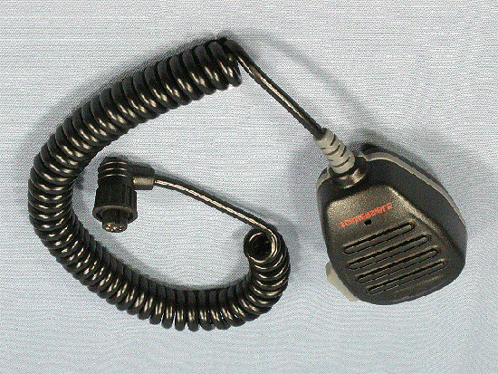
Click to zoom
Application Details
- Equipment Class
- GVH - Part 80 VHF Transmitter (GMDSS)
- Date of Grant
- Oct 16, 2003
- Application Purpose
- Original Equipment
- Date of Application
- Oct 16, 2003
- Equipment Note
- 25 Watts VHF/ FM Marine Transceiver
- Frequency Range
- 156.00000000 - 163.27500000
- Company
- Yaesu Musen Co., Ltd.
- Country
- Japan
Documents & Files
Document Text
Text extracted from the exhibit documents filed with the FCC. Open a document above to read the original.
Users Manual
Page 1GX2360S QUANTUM GX2360S 25 Watt VHF/FM Marine Transceiver Owner's Manual lHuge alphanumeric LCD, knobs and keys lLarge 2.8 inch internal loudspeaker producing louder audio l30 W Loud Hailer with listen back and 4 fog horns, Bells & Whistles lRemovable ClearVoice speaker microphone with 16/9 key and channel selection lDisplay shows channel names, and repeats GPS information ] lCapable of connecting 2 optional RAM+ second station remote micro- phones lDSC distress call automatically broadcasts lat/long and vessel ID ] lDSC position request function and NMEA data input/output to connect to GPS Plotter ] lVersatile user-programmable Scanning, Priority Scan and Dual Watch lNOAA Weather channels and Alert lOne-button access to Channel 16 and 9 lOne-button access to user selectable preset channels lAccess to all US, Canadian and International channels ]with GPS attached GX2360SPage 2 TABLE OF CONTENTS SAFETY/WARNING INFORMATION.............................................................................4 FCC RADIO LICENSE INFORMATION.........................................................................5 FCC NOTICE...................................................................................................................6 GETTING STARTED.......................................................................................................7 ABOUT VHF RADIO................................................................................................7 SELECTING AN ANTENNA....................................................................................7 COAXIAL CABLE......................................................................................................8 1GENERAL INFORMATION.......................................................................................9 1.1INTRODUCTION...............................................................................................9 1.2FCC / INDUSTRY CANADA INFORMATION.................................................9 2PACKING LIST........................................................................................................10 3OPTIONS.................................................................................................................10 4INSTALLATION.......................................................................................................11 4.1LOCATION.......................................................................................................11 4.2ELECTRICAL CONNECTIONS.....................................................................11 4.3ACCESSORY CABLE....................................................................................12 4.4CONNECTION OF GPS WITH NMEA OUTPUT......................................13 4.5CHECKING GPS CONNECTIONS..............................................................14 4.6CHANGING THE GPS TIME.......................................................................14 4.7CHANGING COG TO TRUE OR MAGNETIC..........................................15 4.8OPTIONAL MMB-84 FLUSH MOUNT INSTALLATION..............................16 4.9OPTIONAL CMP25 RAM+ MIC INSTALLATION.......................................17 5CONTROLS AND INDICATORS............................................................................18 5.1CONTROLS AND CONNECTIONS..............................................................18 6BASIC OPERATION................................................................................................23 6.1RECEPTION....................................................................................................23 6.2TRANSMISSION.............................................................................................23 6.3TRANSMIT TIME-OUT TIMER (TOT)...........................................................23 6.4SIMPLEX/DUPLEX CHANNEL USE............................................................24 6.5USA, CANADA, AND INTERNATIONAL MODE..........................................24 6.6NOAA WEATHER CHANNELS....................................................................24 6.7NOAA WEATHER ALERT.............................................................................25 6.8NOAA WEATHER ALERT TESTING...........................................................25 6.9EMERGENCY (CHANNEL 16 USE)............................................................25 6.10CALLING ANOTHER VESSEL (CHANNEL 16 OR 9)..............................26 6.11MAKING TELEPHONE CALLS..................................................................27 6.12OPERATING ON CHANNELS 13 AND 67.............................................27 6.13PROHIBITED COMMUNICATIONS............................................................27 6.14DUAL WATCH (TO CH16)...........................................................................27 6.15MEMORY SCANNING (M-SCAN)...............................................................28 6.16PRIORITY SCANNING (P-SCAN)..............................................................28 6.17CHANNEL A/B INSTANT CALL.................................................................29 6.18PA/FOG OPERATION..................................................................................29 6.19KEYPAD LOCKING......................................................................................30 6.20NAVIGATION INDICATION..........................................................................31 6.21INTERCOM OPERATION............................................................................31 6.22VOICE SCRAMBLER..................................................................................32 6.23RESETTING THE TRANSCEIVER’S MICROPROCESSOR..................32 Page 3GX2360S 7DIGITAL SELECTIVE CALLING............................................................................33 7.1GENERAL........................................................................................................33 7.2DSC SCAN................................................…
Text truncated - open the document above for the full version.
External Photos
FCC ID: K6630043X30 IC ID: 511B-30043X30 Vertex Standard Co., Ltd. Front of EUT Rear of EUT FCC ID: K6630043X30 IC ID: 511B-30043X30 Vertex Standard Co., Ltd. Left Side of EUT Right Side of EUT FCC ID: K6630043X30 IC ID: 511B-30043X30 Vertex Standard Co., Ltd. Top of EUT Bottom of EUT FCC ID: K6630043X30 IC ID: 511B-30043X30 Vertex Standard Co., Ltd. Microphone and Cable Front of Microphone FCC ID: K6630043X30 IC ID: 511B-30043X30 Vertex Standard Co., Ltd. Rear of Microphone DC Cable
ID Label/Location Info
GX2360SGX2360S LABEL DRAWINGLABEL DRAWING Vertex Standard Co., Ltd.Vertex Standard Co., Ltd. (1:1) (1:2) ID / Part 15.19 and CAUTION drawings ID drawing Part 15.19 and CAUTION drawings Label location GX2360S VERTEX STANDARD CO., LTD. MADE IN JAPAN CANADA: 511B-30043X30 FCC ID: K6630043X30 4909959000000 SER NO. 00000000 GX2360S VERTEX STANDARD CO., LTD. MADE IN JAPAN CANADA: 511B-30043X30 FCC ID: K6630043X30 4909959000000 SER NO. 00000000 This device complies with part 15 of the FCC Rules. Operation is subject to the condition that this device does not cause harmful interference. Device restricted to occupational use to satisfy FCC RF exposure compliance. See owner’s manual for specific operating requirement. CAUTION This device complies with part 15 of the FCC Rules. Operation is subject to the condition that this device does not cause harmful interference. Device restricted to occupational use to satisfy FCC RF exposure compliance. See owner’s manual for specific operating requirement. CAUTION
Internal Photos
FCC ID: K6630043X30 IC ID: 511B-30043X30 Vertex Standard Co., Ltd. Top of EUT without Case Bottom of EUT without Case (with Shield Cases) FCC ID: K6630043X30 IC ID: 511B-30043X30 Vertex Standard Co., Ltd. Bottom of EUT without Case (without Shield Cases) Inside of Panel with PWB (1) FCC ID: K6630043X30 IC ID: 511B-30043X30 Vertex Standard Co., Ltd. Inside of Panel with PWB (2) Side-A of MAIN-UNIT with Shield Case FCC ID: K6630043X30 IC ID: 511B-30043X30 Vertex Standard Co., Ltd. Side-A of MAIN-UNIT without Shield Case Side-B of MAIN-UNIT FCC ID: K6630043X30 IC ID: 511B-30043X30 Vertex Standard Co., Ltd. Side-A of CNTL-UNIT with LCD Side-A of CNTL-UNIT without LCD FCC ID: K6630043X30 IC ID: 511B-30043X30 Vertex Standard Co., Ltd. Side-B of CNTL-UNIT Front of LCD FCC ID: K6630043X30 IC ID: 511B-30043X30 Vertex Standard Co., Ltd. Rear of LCD Side-A of PA-UNT FCC ID: K6630043X30 IC ID: 511B-30043X30 Vertex Standard Co., Ltd. Side-B of PA-UNIT Top of Chassis FCC ID: K6630043X30 IC ID: 511B-30043X30 Vertex Standard Co., Ltd. Bottom of Chassis Inside of Panel without PWB FCC ID: K6630043X30 IC ID: 511B-30043X30 Vertex Standard Co., Ltd. Inside of Microphone (1) Inside of Microphone (2)
Operational Description
FCC ID: K6630043X30 IC ID: 511B-30043X30 Circuit Description Vertex Standard Co., Ltd. 1 GX2360S Circuit Description Reception and transmission are switched by “RX-CNTL” and “TX-CNTL” lines from the CNTL Unit. The receiver uses double-conversion superheterodyne circuitry, with a 21.4 MHz 1st IF and 450 kHz 2nd IF. The 1st local is produced by a PLL synthesizer, yielding the 21.4 MHz 1st IF. The 2nd local uses a 21.850 MHz crystal oscillator, yielding the 450 kHz 2nd IF. The 2nd mixer and other circuits use a custom IC to convert and amplify the 2nd IF and detect FM to obtain demodulated signals. During transmit, the PLL synthesizer oscillates at the desired frequency directly, for amplification to obtain RF power output. During transmit, voice modulation is applied to this synthesizer. Transceiver functions, such as TX/RX control, PLL synthesizer settings, and channel programming, are controlled using the MPU. Receiver Incoming RF signals from the antenna connector are delivered to the RF Unit, and pass through a low-pass filter (LPF) consisting of coils and capacitors, and antenna switching diodes D1003 and D1004 for delivery to the receiver front end. Signals within the frequency range of the transceiver are then passed through a band- pass filter consisting of T1001 and T1002 before RF amplification by Q1016. The amplified RF is then band-pass filtered again by T1003, T1004, and T1005, to ensure pure in-band input to 1st mixer Q1024. Buffered output from the VCO is amplified by Q1022 and band-pass filtered by L1013, L1015, C1125, C1131, and C1134, to provide a pure 1st local signal between 134.65 and 140.625 MHz for delivery to the 1st mixer. The 21.4 MHz 1st mixer product then passes through dual monolithic crystal filter XF1001 (±6.5 kHz BW), and is amplified by Q1031 and delivered to the input of the FM IF subsystem IC Q1036. This IC contains the 2nd mixer, 2nd local oscillator, limiter amplifier, FM detector, noise amplifier, and squelch gates. The 2nd local is produced by crystal X1001 (21.850 MHz) then passes through the amplifier Q1017, and delivered to the 2nd mixer in the IF-IC. The 1st IF is converted to 450 kHz by the 2nd mixer and stripped of unwanted components by ceramic filter CF1001. After passing through a limiter amplifier, the signal is demodulated by the FM detector. Demodulated receive audio from the IF-IC is amplified by Q1038, then the signal is through the AF switch Q1040, the AF amplifier Q1045 and the AF Mute switch Q1035 . After volume adjustment by the D/A converter Q1033 and the AF power amplifier Q1043, the audio signal is passed to the external Speaker terminal in the accessory cable and 16- Ω internal loudspeaker. FCC ID: K6630043X30 IC ID: 511B-30043X30 Circuit Description Vertex Standard Co., Ltd. 2 PLL Synthesizer The 1st LO maintains stability from the PLL synthesizer by using a 21.850 MHz reference signal from crystal X1001. PLL synthesizer IC Q1021 consists of a prescaler, reference counter, swallow counter, programmable counter, a serial data input port to set these counters based on the external data, a phase comparator, and a charge pump. The PLL-IC divides the 21.850 MHz reference signal by 874 using the reference counter (25 kHz comparison frequency). The VCO output is divided by the prescaler, swallow counter and programmable counter. These two signals are compared by the phase comparator and applied to the charge pump. A voltage proportional to their phase difference is delivered to the low-pass filter circuit, then fed back to the VCO as a voltage with phase error, controlling and stabilizing the oscillating frequency. This synthesizer also operates as a modulator during transmit. The RX VCO is comprised of Q1027 and D1009/1010/1014/1015; it oscillates at 21.4 MHz below. The TX VCO is comprised of Q1029 and D1012; it oscillates at the fundamental frequency, with direct frequency-modulation using varactor diode D1016. The VCO output passes through buffer amplifier Q1022 to obtain stable output. The VCO DC supply is regulated by Q1018. Synthesizer output is fed to the 1st mixer by diode switch D1006 during receive, and to drive amplifier Q1014, and the RF power amplifier Q1007 for transmit. The reference oscillator feeds the PLL synthesizer. Transmitter Voice audio from the microphone is delivered via the MIC connector to the RF Unit. After passing through amplifier Q1028, a pre-emphasis network, the D/A converter Q1033 for MIC switch, the MIC mute switch Q1035, limiter (IDC: instantaneous deviation control), and LPF Q1028, the audio is adjusted for optimum deviation level and delivered to the next stage. Voice or DSC(Digital Selective Calling) encode signal inputs from the LPF Q1028 are FM-modulated in the VCO of the synthesizer. Synthesizer output, after passing through diode switch D1006, is amplified by driver Q1014, and the RF power amplifier Q1007 to obtain full RF output. The RF energy then passes through antenna switch D1003 and a low-pass filter circuit and finally to the antenna connector. RF output power from the final amplifier is sampled by C1013 and C1019 and is rectified by D1002. The resulting DC is fed through Automatic Power Controllers Q1034 to transmitter RF power amplifier Q1007, thus providing positive control of the power output. Generation of spurious products by the transmitter is minimized by the fundamental carrier frequency being equal to the final transmitting frequency, modulated directly in the transmit VCO. Additional harmonic suppression is provided by a low-pass filter consisting of coils and capacitors, resulting in more than 70 dB of harmonic suppression prior to delivery of the RF energy to the antenna. FCC ID: K6630043X30 IC ID: 511B-30043X30 Circuit Description Vertex Standard Co., Ltd. 3 DSC Encoder/ Decoder Encoder The DCS (Digital Selective Calling) encode signal which D/A converted in the 16-bit MPU IC Q2004 is fed through the low-pass filter Q1028 on the RF Unit to the VCO. Decoder The receiving DC…
Text truncated - open the document above for the full version.
Parts List/Tune Up Info
FCC ID: K6630043X30 IC ID: 511B-30043X30 Alignment Vertex Standard Co,. Ltd. 1 GX2360S Alignment The GX2360S has been carefully aligned at the factory for the specified performance across the marine band. Realignment should therefore not be necessary except in the event of a component failure. All component replacement and service should be performed only by an authorized Standard Horizon representative, or the warranty policy may be voided. The following procedures cover the sometimes critical and tedious adjustments that are not normally required once the transceiver has left the factory. However, if damage occurs and some parts are replaced, realignment may be required. If a sudden problem occurs during normal operation, it is likely due to component failure; realignment should not be done until after the faulty component has been replaced. We recommend that servicing be performed only by authorized Standard Horizon service technicians who are experienced with the circuitry and fully equipped for repair and alignment. Therefore, if a fault is suspected, contact the dealer from whom the transceiver was purchased for instructions regarding repair. Authorized Standard Horizon service technicians realign all circuits and make complete performance checks to ensure compliance with factory specifications after replacing any faulty components. Those who do undertake any of the following alignments are cautioned to proceed at their own risk. Problems caused by unauthorized attempts at realignment are not covered by the warranty policy. Also, Standard Horizon, a division of VERTEX STANDARD, must reserve the right to change circuits and alignment procedures in the interest of improved performance, without notifying owners. Under no circumstances should any alignment be attempted unless the normal function and operation of the transceiver are clearly understood, the cause of the malfunction has been clearly pinpointed and any faulty components replaced, and the need for realignment determined to be absolutely necessary. The following test equipment (and thorough familiarity with its correct use) is necessary for complete realignment. Correction of problems caused by misalignment resulting from use of improper test equipment is not covered under the warranty policy. While most steps do not require all of the equipment listed, the interactions of some adjustments may require that more complex adjustments be performed afterwards. Do not attempt to perform only a single step unless it is clearly isolated electrically from all other steps. Have all test equipment ready before beginning, and follow all of the steps in a section in the order presented. FCC ID: K6630043X30 IC ID: 511B-30043X30 Alignment Vertex Standard Co,. Ltd. 2 Required Test Equipment RF Signal Generator with calibrated output level at 200 MHz Deviation Meter (linear detector) AF Millivoltmeter SINAD Meter Inline Wattmeter with 5% accuracy at 200 MHz Regulated DC Power Supply: 13.8 VDC, 10A 50 Ω Non-reactive Dummy Load: 30W at 200 MHz Frequency Counter: >0.1 ppm accuracy at 200 MHz AF Signal Generator DC Voltmeter: high impedance VHF Sampling Coupler AF Dummy Load: 4 Ω , 10 W Oscilloscope Spectrum Analyzer GX1260S Marine Transceiver Alignment Preparation & Precautions A dummy load and inline wattmeter must be connected to the main antenna jack in all procedures that call for transmission. Correct alignment is not possible with an antenna. After completing one step, read the following step to determine whether the same test equipment will be required. If not, remove the test equipment (except dummy load and wattmeter, if connected) before proceeding. Correct alignment requires that the ambient temperature be the same as that of the transceiver and test equipment, and that this temperature be held constant between 20°C and 30°C (68°F and 86°F). When the transceiver is brought into the shop from hot or cold air it should be allowed some time for thermal equalization with the environment before alignment. If possible, alignments should be made with oscillator shields and circuit boards firmly affixed in place. Also, the test equipment must be thoroughly warmed up before beginning. Note: Signal levels in dB referred to in this procedure are based on 0 dBμ = 0.5 μV (closed circuit). FCC ID: K6630043X30 IC ID: 511B-30043X30 Alignment Vertex Standard Co,. Ltd. 3 Overview of Test Mode The test mode has been build in the microprocessor in order to adjust and confirm the performance of transceiver. The purpose is to adjust transceiver simply and to confirm the performance of transceiver smoothly. (a) Expansion channels “EXP01 - EXP07” will be set as follows: DISPLAYRX FrequencyTX FrequencySCAN Channel EXP01156.050 MHz156.050 MHzX EXP02---157.425 MHzX EXP03163.275 MHz---X EXP04155.050 MHz155.050 MHzO EXP05162.025 MHz162.025 MHzX EXP06163.575 MHz158.975 MHzX WX10163.275 MHz---O (B) In CH70, ever time you are in transmit mode, (every time you press PTT), the following test tone can be outputted: 1st transmission:Synthetic tone of 1300 Hz and 2100 Hz 2nd transmission:1300 Hz 3rd transmission:2100 Hz 4th transmission:No Modulation 5th transmission:Return to 1st transmission (C) Scan the channels between WX10 and EXP04 in the SCAN mode. Adjustment of PLL Frequency Adjust the frequency in the transmit mode and local frequency in the receive mode. -- Adjustment -- Setup the test equipment as shown below. Set the channel to CH16. With the PTT switch pressed, adjust TC1001 so that RF frequency is 156.80000 MHz ± 100 Hz. Adjustment of VCO Adjust the frequency in the receive mode. -- Adjustment -- Setup the test equipment as shown below. Connect the DC voltmeter to the test point (TP1009). Set the channel to CH16. With the PTT switch pressed, adjust TC1002 so that DC voltage is 1.5 V ± 0.1 V. FCC ID: K6630043X30 IC ID: 511B-30043X30 Alignment Vertex Standard Co,. Ltd. 4 Adjustment of Receiver Front-end Adjust the rece…
Text truncated - open the document above for the full version.
Parts List/Tune Up Info
1/2 Component Application AddressDevice nameDescriptionApplication [MAIN-UNIT] D 1001 Diode1N5402Reverse Voltage Protection D 1002 Diode1SS321Power Detector D 1003 DiodeXB15A308Antenna Switch D 1004 DiodeXB15A308Antenna Switch D 1005 DiodeHSU277RF Over Input Protection D 1006 DiodeDAN235UTx/Rx RF Switch D 1008 DiodeHZU5ALLPLL Charge Pump D 1009 Varactor DiodeHVC306BVCO D 1010 Varactor DiodeHVC306BVCO D 1012 Varactor DiodeHVC306BVCO D 1013 Diode1SS302PLL L.P.Filter D 1014 Varactor DiodeHVC306BVCO D 1015 Varactor DiodeHVC306BVCO D 1016 Varactor DiodeHVC306BVCO Modulation D 1017 Zener DiodeHZM5.6NB2RX 5V Regulator D 1018 DiodeDA221Rectifier D 1019 DiodeDA221Rectifier D 1020 DiodeHSU277RF Over Input Protection Q 1001 Transistor2SB1301-ZQDC AMP Q 1002 Transistor2SB1201-ZQDC AMP Q 1003 ICNJM7808FA8V Regulator Q 1004 ICRT1N441UTx Mute Switch Q 1005 ICRT1N241MDC Switch Q 1006 ICRT1N241MDC Switch Q 1007 ICRA35H1516M-01RF Power MODULE Q 1008 ICNJM78M05DL1A5V Regulator Q 1009 ICDTB123EKTx 8V Switch Q 1010 Transistor2SA1602ADC AMP Q 1011 ICRT1N441UTx 8V Switch Q 1012 ICRT1N441UTX H/L Cntrol Q 1013 ICRT1N441URx 8V Switch Q 1014 Transistor2SC3357Driver AMP Q 1016 Transistor2SC5006RF AMP Q 1017 Transistor2SC4154EBuff AMP Q 1018 Transistor2SC4154ERipple Filter Q 1019 Transistor2SA1602AUnlock Switch Q 1020 ICRT1N241MDC Switch Q 1021 ICMB15A02PFV1PLL Subsystem Q 1022 Transistor2SC5006VCO Buff AMP Q 1023 ICRT1N441MDC Switch Q 1024 FET3SK320RX 1st Mixer Q 1025 Transistor2SA1162GRPLL Charge Pump Q 1026 Transistor2SC2712GRPLL Charge Pump Q 1027 FET2SK520-K43RX VCO Q 1028 ICNJM12902VMIC AMP, Limitter, Low Pass Filter, AF Comparator Q 1029 Transistor2SC5006TX VCO Q 1030 ICRT1N441UDC Switch Q 1031 Transistor2SC4400IF AMP Q 1032 ICRT1N441UModuration Switch Q 1033 ICM62364FPMIC Selector, TX H/L Switch, AF Volume Q 1034 ICNJM2904VAPC Q 1035 ICBU4066BCFVAF Mute Switch, MIC Mute Switch Q 1036 ICTA31136FNIF Subsystem Q 1037 Transistor2SC4154EAF AMP Q 1038 Transistor2SC4154EAF AMP Q 1039 Transistor2SC4154ENoise AMP Q 1040 ICBU4053BCFVAF Switch Q 1041 ICNJM2211MFSK Decorder Q 1042 TransistorRT1N241MAF Mute Switch Q 1043 ICLA4425AAF Power AMP Q 1045 ICNJM12902VAF Buffer AMP [CNTL-UNIT] D 2001 Diode MC2846 FOG Control D 2002 LED FY1111C-722 Back Light LED D 2003 LED FY1111C-722 Back Light LED D 2004 LED FY1111C-722 Back Light LED D 2005 LED FY1111C-722 Back Light LED D 2006 LED FY1111C-722 Back Light LED D 2007 LED FY1111C-722 Back Light LED D 2008 LED FY1111C-722 Back Light LED D 2009 LED FY1111C-722 Back Light LED FCC ID: K6630043X30 IC ID: 511B-30043X30 Vertex Standard Co., Ltd. 2/2 Component Application AddressDevice nameDescriptionApplication FCC ID: K6630043X30 IC ID: 511B-30043X30 D 2010 LED FY1111C-722 Back Light LED D 2011 LED FY1111C-722 Back Light LED D 2012 LED FY1111C-722 Back Light LED D 2013 LED FY1111C-722 Back Light LED D 2010 LED FY1111C-722 Back Light LED D 2014 Diode 1SS355 Protector D 2015 Diode HZM27WA Protector D 2016 Diode HZM27WA Protector D 2017 Diode HZM27WA Protector D 2018 Diode HZM27WA Protector Q 2001 IC NJM78L05UA Regulator Q 2002 Transistor DTC144EE Detector Q 2003 IC PST597CN Reset Q 2004 IC M30620FCAGP CPU Q 2005 Transistor DTA144EE FOG Control Q 2006 IC BR24L64F EEPROM Q 2007 Transistor 2SC4154E DC AMP Q 2008 Transistor CPH6102 DC AMP Q 2009 Transistor 2SC4154E Lamp Switch Q 2010 IC HD66712SA00FS LCD Driver Q 2011 Transistor 2SA1602A Driver Q 2012 Transistor 2SC4154E Driver Q 2013 IC TLP281 Detector Q 2014 Transistor 2SA1602A Driver Q 2015 Transistor 2SC4154E Driver Q 2016 IC TC74HC14AF Driver Q 2017 Transistor 2SA1602A Driver Q 2018 Transistor 2SC4154E Driver Q 2019 Transistor DTC144EE Switch Q 2020 Transistor DTC144EE Switch [PA-UNIT] D 3001 Diode D1F20 Protection Q 3001 IC NJM2904V AF Buff / AF Amp. Q 3002 IC TA8225H AF PA Q 3003 IC RT1N241M AF Switch Vertex Standard Co., Ltd.
Test Report
FCC ID: K6630043X30 Transmitter Certification of FCC ID: K6630043X30 Model: GX2360S to Federal Communications Commission Rule Part(s) 80, Confidentiality Date Of Report: October 3, 2003 On the Behalf of the Applicant: Vertex Standard Co., Ltd. At the Request of: P.O. UPS 9/23/2003 Vertex Standard USA Inc. 10900 Walker Street Cypress, CA 90630 Attention of: Mikio Maruya, Executive Vice President (800) 255-9237; FAX: (800) 477-9237 (714) 827-7600; FAX: -8100 [email protected] Supervised By: Morton Flom, P. Eng. MFA p0390002, d03a0008 FCC ID: K6630043X30 List of Exhibits (FCC Certification (Transmitters) - Revised 9/28/98) Applicant: Vertex Standard Co., Ltd. FCC ID: K6630043X30 By Applicant: 1. Letter of Authorization x 2. Identification Drawings, 2.1033(c)(11) x Label x Location of Label x Compliance Statement x Location of Compliance Statement 3. Photographs, 2.1033(c)(12) x 4. Documentation: 2.1033(c) (3) User Manual x (9) Tune-Up/Alignment Procedure x (10) Schematic Diagram x (10) Operational Description x Block Diagram x Active Devices x 5. MPE Report x 6. Confidentiality Request x By M.F.A. Inc. A. Testimonial & Statement of Certification B. Statement of Qualifications MFA p0390002, d03a0008 FCC ID: K6630043X30 The applicant has been cautioned as to the following: 15.21 Information To User. The users manual or instruction manual for an intentional radiator shall caution the user that changes or modifications not expressly approved by the party responsible for compliance could void the user's authority to operate the equipment. 15.27(a) Special Accessories. Equipment marketed to a consumer must be capable of complying with the necessary regulations in the configuration in which the equipment is marketed. Where special accessories, such as shielded cables and/or special connectors are required to enable an unintentional or intentional radiator to comply with the emission limits in this part, the equipment must be marketed with, i.e. shipped and sold with, those special accessories. However, in lieu of shipping or packaging the special accessories with the unintentional or intentional radiator, the responsible party may employ other methods of ensuring that the special accessories are provided to the consumer, without additional charge. Information detailing any alternative method used to supply the special accessories for a grant of equipment authorization or retained in the verification records, as appropriate. The party responsible for the equipment, as detailed in § 2.909 of this chapter, shall ensure that these special accessories are provided with the equipment. The instruction manual for such devices shall include appropriate instructions on the first page of text concerned with the installation of the device that these special accessories must be used with the device. It is the responsibility of the user to use the needed special accessories supplied with the equipment. MFA p0390002, d03a0008 FCC ID: K6630043X30 Table of Contents Rule Description Page . Test Report 1 2.1033(c) General Information Required 2 2.1033(c)(14) Rule Summary 5 . Standard Test Conditions and Engineering Practices 6 80.365 VHF Radiotelephone Frequencies 7 2.1046(a) ERP Carrier Power (Radiated) 8 2.1047(a) Audio Frequency Response 9 2.1047(a) Audio Low Pass Filter (Voice Input) 12 2.1047(b) Modulation Limiting 14 2.1049(c)(1) Emission Masks (Occupied Bandwidth) 16 2.1051 Spurious Emissions at Antenna Terminals) 19 2.1053(a) Field Strength of Spurious Radiation 22 2.1055(a)(1) Frequency Stability (Temperature Variation) 26 2.1055(b)(1) Frequency Stability (Voltage Variation) 29 80.203(b) User Controls 30 80.203(c) Automatic Deactivation (Time-Out Timer) 31 80.959(c)(1)(2)&(3) Power Output Over Time 32 80.225 Requirements for DSC 35 80.959(a)&(b) Subpart T – G3E Emissions 39 80.956(a)&(b) Subpart T – G3E Emissions 40 80.961(a)&(b) Subpart T – G3E Emissions 41 80.1011, 80.1013 Subpart U – Bridge-to-Bridge Act 42 2.202(g) Necessary Bandwidth and Emission Bandwidth 43 MFA p0390002, d03a0008 FCC ID: K6630043X30 Page Number 1 of 43. Required information per ISO/IEC Guide 25-1990, paragraph 13.2: a) Test Report b) Laboratory: (FCC: 31040/SIT) (Canada: IC 2044) M. Flom Associates, Inc. 3356 N. San Marcos Place, Suite 107 Chandler, AZ 85225 c) Report Number: d03a0008 d) Client: Vertex Standard USA Inc. 10900 Walker Street Cypress, CA 90630 e) Identification: GX2360S FCC ID: K6630043X30 Description: 25 Watt VHF/FM Marine Transceiver f) EUT Condition: Not required unless specified in individual tests. g) Report Date: October 3, 2003 EUT Received: September 23, 2003 h, j, k): As indicated in individual tests. i) Sampling method: No sampling procedure used. l) Uncertainty: In accordance with MFA internal quality manual. m) Supervised by: Morton Flom, P. Eng. n) Results: The results presented in this report relate only to the item tested. o) Reproduction: This report must not be reproduced, except in full, without written permission from this laboratory. MFA p0390002, d03a0008 FCC ID: K6630043X30 Page Number 2 of 43. List of General Information Required for Certification In Accordance with FCC Rules and Regulations, Volume II, Part 2 and to 80, Confidentiality Sub-Part 2.1033 (c)(1): Name And Address Of Applicant: Vertex Standard Co., Ltd. 4-8-8 Nakameguro, Meguro-Ku Tokyo 153-8644 Japan Manufacturer: Applicant (c)(2): FCC ID: K6630043X30 Model Number: GX2360S (c)(3): Instruction Ma…
Text truncated - open the document above for the full version.
Contact Information
Applicant
Masatoshi Muraishi(Engineering Division)
Test Firm
M. Flom Associates, Inc.Morton Flom
Technical Specifications
| # | Rule Parts | Frequency Range | Power Output | Emission | Tolerance |
|---|---|---|---|---|---|
| 6 | 80.1101(c)(4) | 156 MHz - 163.275 MHz | 25 W | 16K0G2B | 5 ppm |
Other Applications from Yaesu Musen Co., Ltd.
K660E180X10
Dec 01, 2025BLUETOOTH MICROPHONE
Equipment Class
DTS - Digital Transmission System
K6630673Y3D
Aug 01, 2024VHF FM Marine Transceiver
Equipment Class
CXX - Communications Rcvr for use w/ licensed Tx and CBs
K6630653Y3D
Aug 01, 2024VHF FM Marine Transceiver
Equipment Class
CXX - Communications Rcvr for use w/ licensed Tx and CBs
K6630683X30
Jan 10, 2023VHF FM Marine Transceiver
Equipment Class
TNF - Licensed Non-Broadcast Transmitter Held to Face
K6650033X30
Nov 18, 2020Airband Radio Transceiver
Equipment Class
TNF - Licensed Non-Broadcast Transmitter Held to Face