K6630493X20Handheld Marine Transceiver with WX
Yaesu Musen Co., Ltd.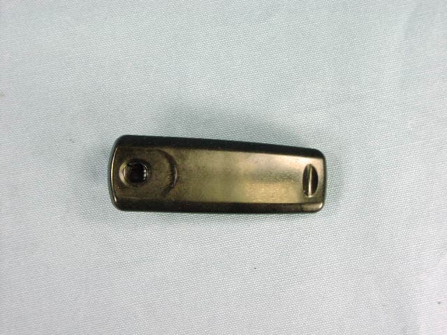
Click to zoom
Application Details
- Equipment Class
- TNF - Licensed Non-Broadcast Transmitter Held to Face
- Date of Grant
- Apr 01, 2012
- Application Purpose
- Original Equipment
- Date of Application
- Feb 15, 2012
- Equipment Note
- Handheld Marine Transceiver with WX
- Frequency Range
- 156.02500000 - 157.42500000
- Company
- Yaesu Musen Co., Ltd.
- Country
- Japan
Documents & Files
Document Text
Text extracted from the exhibit documents filed with the FCC. Open a document above to read the original.
Users Manual
Page 1HX300 HX300 Floating VHF FM Marine Transceiver Owner’s Manual HX300Page 2 TABLE OF CONTENTS Quick Reference Guide ....................................................................................................................................3 1. GENERAL INFORMATION ........................................................................................................................4 1.1 INTRODUCTION............................................................................................................................4 1.2 SAFETY INFORMATION ..............................................................................................................5 2. ACCESSORIES ..........................................................................................................................................6 2.1 PACKING LIST ..............................................................................................................................6 2.2 OPTIONS .......................................................................................................................................6 3. ABOUT THIS RADIO ................................................................................................................................7 3.1 ABOUT THE VHF MARINE BAND ............................................................................................7 3.2 ABOUT WATER RESISTANCE ...................................................................................................7 3.3 DISTRESS AND HAILING ( CHANNEL 16 ) ................................................................................7 3.4 CALLING ANOTHER VESSEL ( CHANNEL 16 OR 9 ) ...............................................................8 3.5 OPERATING ON CHANNEL 13 ..................................................................................................9 3.6 OPERATING ON CHANNEL 67 ..................................................................................................9 3.7 SIMPLEX / DUPLEX CHANNEL USE ..........................................................................................9 4. GETTING STARTED................................................................................................................................10 4.1 RADIO CARE ...............................................................................................................................10 4.2 BATTERIES AND CHARGERS ..................................................................................................10 4.2.1 BATTERY SAFETY .........................................................................................................10 4.2.2 BATTERY INSTALLATION / REMOVAL ..........................................................................12 4.2.3 BATTERY CHARGING ....................................................................................................12 4.3 BELT CLIP INSTALLATION / REMOVAL ...................................................................................13 HAND STRAP INSTALLATION ..................................................................................................13 4.4 INSTALLATION OF OPTION .....................................................................................................14 4.3.1 FBA-44 ALKALINE BATTERY CASE ............................................................................14 5. CONTROLS AND INDICATORS ............................................................................................................15 5.1 CONTROLS AND SWITCHES ...................................................................................................15 5.2 LCD INDICATORS ......................................................................................................................18 6. BASIC OPERATION ................................................................................................................................20 6.1 PROHIBITED COMMUNICATIONS ............................................................................................20 6.2 INITIAL SETUP ...........................................................................................................................20 6.3 RECEPTION ................................................................................................................................20 6.4 TRANSMISSION ..........................................................................................................................21 6.4.1 TRANSMIT TIME-OUT TIMER ( TOT ) ..............................................................................21 WATER HAZARD LAMP ............................................................................................................21 6.5 USA, CANADIAN, AND INTERNATIONAL CHANNELS ..........................................................22 6.6 KEYPAD LOCKING .....................................................................................................................22 6.7 NOAA WEATHER CHANNELS ..................................................................................................22 6.7.1 NOAA WEATHER ALERT ................................................................................................22 6.7.2 NOAA WEATHER ALERT TESTING ................................................................................23 6.8 PRESET CHANNELS ( 0 ~ 9 ) : INSTANT ACCESS ...................................................................23 6.8.1 PROGRAMMING .............................................................................................................23 6.8.2 OPERATION .....................................................................................................................24 6.8.3 DELETING A PRESET CHANNEL ................................................................................24 6.9 SCANNING ..........................................................................................…
Text truncated - open the document above for the full version.
Attestation Statements
December 21, 2011 Federal Communications Commission Authorization and Evaluation Division, 7435 Oakland Mills Road Columbia, MD 21046 USA Re: HX300 (FCC ID: K6630493X20) Gentlemen: Part 15.19 Compliance Statement is placed on the rear of case. Sincerely, Vertex Standard Co., Ltd. Yukimasa Tomita Executive Managing Officer Engineering Division
Attestation Statements
December 21, 2011 Federal Communications Commission Authorization and Evaluation Division, 7435 Oakland Mills Road Columbia, MD 21046 USA Re: HX300 (FCC ID: K6630493X20) Gentlemen: A. Part 15.21 Compliance Statement Drawing: B. Part 15.21 Compliance Statement Drawing Location: IN OPERATION MANUAL (location on the page 43) Sincerely, Vertex Standard Co., Ltd. Yukimasa Tomita Executive Managing Officer Engineering Division Part 15.21: Changes or modifications to this device not expressly approved by Vertex Standard could void the user’s authorization to operate this device. 20mm 120mm
Cover Letter(s)
December 21, 2011 Federal Communications Commission EQUIPMENT APPROVAL SERVICES P. O. Box 358315 Pittsburgh, PA 15251-5315 Attention: Authorization and Evaluation Division Reference: HX300 (FCC ID: K6630493X20) Pursuant to Sections 0.457 (d)(1)(ii) and 0.459 of the Commission’s Rules, the Applicant hereby requires confidential treatment of some of the information accompanying this Application, as listed below: ・ Block Diagram ・ Schematics These materials contain trade secrets and proprietary information not customarily released to the public. The public disclosure of these matters might be harmful to the Applicant and provide unjustified benefits to its competitors. The Applicant understands that pursuant to Rule 0.457 (d)(1)(ii), disclosure of the Application and all accompanying documentation will not be made before the date of Grant for this Application. Sincerely, Vertex Standard Co., Ltd Yukimasa Tomita Executive Managing Officer Engineering Division
Cover Letter(s)
TCB FCC Approvals FCB Industry Canada Approval NB Notified Body for Europe 849 NW State Road 45 P. O. Box 370 Newberry, Florida 32669 USA Telephone (352) 472-5500 (888) 472-2424 FAX (352) 472-2030 email: [email protected] March 30, 2012 Federal Communications Commission Authorization and Evaluation Division 7435 Oakland Mills Road Columbia, MD 21045 Ref: Yaesu Musen Co., Ltd. FCC ID: K6630493X20 Correspondence Reference #: 41470, 41469 731 Confirmation #: EA546633 Attention: Tim Harrington Dear Tim: In response to your correspondence: 1. The exhibit entitled “Test Report 2” has been modified and a revised report uploaded to remove the 25W. 2. Regarding the power levels: a. The EMC/radio report has been modified to show 4.8 Watts. The 4.48 Watts was a typing error. b. A revised tuning procedure has been uploaded to show the correct output power. Should you have any questions or require any further information, please advise. Regards, Mario R. de Aranzeta
External Photos
FCC ID:K6630493X20 IC: 511B-30493X20 Vertex Standard Co., Ltd. 1 Front view with Antenna Rear view without Antenna and Belt Clip FCC ID:K6630493X20 IC: 511B-30493X20 Vertex Standard Co., Ltd. 2 Front view without Antenna Rear view without Battery and Belt Clip FCC ID:K6630493X20 IC: 511B-30493X20 Vertex Standard Co., Ltd. 3 Right view Left view FCC ID:K6630493X20 IC: 511B-30493X20 Vertex Standard Co., Ltd. 4 Top view Bottom view FCC ID:K6630493X20 IC: 511B-30493X20 Vertex Standard Co., Ltd. 5 Battery Pack (FNB-122LI) Battery Pack (FNB-122LI) FCC ID:K6630493X20 IC: 511B-30493X20 Vertex Standard Co., Ltd. 6 Alkaline Battery Case (FBA-44) AC Adapter (PA-54B) and USB Cable FCC ID:K6630493X20 IC: 511B-30493X20 Vertex Standard Co., Ltd. 7 Antenna (CAT460) Belt Clip (Clip-22)
ID Label/Location Info
HX300HX300 LABEL DRAWINGLABEL DRAWING Vertex Standard Co., Ltd.Vertex Standard Co., Ltd. ID / Part 15.19 and CAUTION drawings ID drawing Part 15.19 and CAUTION drawings Label location Model: HX300 K6630493X20 511B-30493X20 4909959000000 This device complies with part 15 of the FCC Rules. Operation is subject to the condition that this device does not cause harmful interference. VERTEX SATANDARD CO., LTD. MADE IN CHINA 1M000010
Internal Photos
FCC ID:K6630493X20 IC ID: 511B-30493X20 Vertex Standard Co., Ltd. Side-A of MAIN-UNIT with LCD Side-A of MAIN-UNIT without LCD FCC ID:K6630493X20 IC ID: 511B-30493X20 Vertex Standard Co., Ltd. Side-B of MAIN-UNIT with chassis and Shield Cover Side-B of MAIN-UNIT without chassis and Shield Cover FCC ID:K6630493X20 IC ID: 511B-30493X20 Vertex Standard Co., Ltd. View of chassis View of chassis FCC ID:K6630493X20 IC ID: 511B-30493X20 Vertex Standard Co., Ltd. LCD (Front) LCD (Back) FCC ID:K6630493X20 IC ID: 511B-30493X20 Vertex Standard Co., Ltd. Inside of front case Inside of rear case
Operational Description
FCC ID: K6630493X20 IC: 511B-30493X20 Circuit Description 1/2 Vertex Standard Co., Ltd. HX300 Circuit Description 1. Receive Signal Path Incoming RF from the antenna jack is delivered to the RF Unit and passes through a low-pass filter consisting of coils L1001, L1003 and L1006,capacitors C1014, C1016, C1020,C1023,C1029,C1033 and C1042, and antenna switching diode D1005. Signals within the frequency range of the transceiver enter a band-pass filter consisting of coils L1018 and L1020, capacitors C1096, C1098 and C1102, then amplified by Q1023. The amplified RF is then passed through a SAW filter XF1001, the pure in-band input signal is delivered to 1st mixer Q1034. Buffered output from the VCO is amplified by Q1006 to provide a pure first local signal between 134.35 and 141.575 MHz for injection to the first mixer Q1034. The 21.7 MHz first mixer product then passes through monolithic crystal filter XF1002/XF1003 to strip away all but the desired signal, which is then amplified by Q1039. The amplified first IF signal is applied to FM IF subsystem IC Q1041, which contains the second mixer, second local oscillator, limited amplifier, noise amplifier, and RSSI amplifier. A second local signal is produced from the PLL reference/second local oscillator of X1001 (21.25 MHz). The 21.25 MHz reference signal is delivered to mixer section of Q1041 which produce the 450 kHz second IF mixed with the first IF signal. The second IF then passes through the ceramic filter CF1001 to strip away unwanted mixer products, and is then applied to the limited amplifier in Q1041, which removes amplitude variations in the 450kHz IF, before detection of the speech by the ceramic discriminator CD1001. 2. Audio Amplifier The demodulated audio signal from the Q1041 passes through a band-pass filter and High-pass filter, then applied to the de-emphasis of Q1005. Then passes through the audio mute switch Q1036, the Electric Volume audio volume Q1035 and the audio power amplifier Q1043, providing up to 700 mW of audio power to the 8 Ω loudspeaker. 3. Squelch Control The squelch circuitry consists of a noise amplifier and band-pass filter and noise detector within Q1041. When no carrier received, noise at the output of the detector stage in Q1041 is amplified and band-pass filtered by the noise amplifier section of Q1041 and the network between pins 7 and 8, and then rectified by detection circuit in Q1041. The resulting DC squelch control voltage is passed to pin 100 of the microprocessor Q1033. If no carrier is received, this signal causes pin 82 of Q1033 to go low and the Electric Volume audio volume Q1035 is mute. The Electric Volume audio volume Q1035 is disable the supply voltage to the audio amplifier Q1043. Thus, the microprocessor blocks output from the audio amplifier, and silences the receiver, while no signal is being received (and during transmission, as well). 4. Transmit Signal Path The speech input from the microphone MC1001 passes through the audio amplifier Q1003, which is adjusted the microphone gain. The speech signal passes through pre-emphasis circuit to Q1003, which contains the IDC, and low-pass filter. The filtered audio signal is applied to varactor diode D1016, which frequency modulates the VCO Q1013. The modulated signal from the VCO Q1013 is buffered by Q1006. The low-level transmit signal is then passes through the TX switching diode D1028 to the buffer amplifier Q1032, driver amplifier Q1028, then amplified transmit signal is applied to the final amplifier Q1018,1019 up to 5.0 watts output power. The transmit signal then passes through the antenna switch D1005 and is low-pass FCC ID: K6630493X20 IC: 511B-30493X20 Circuit Description 2/2 Vertex Standard Co., Ltd. filtered to suppress harmonic spurious radiation before delivery to the antenna. 4-1 Automatic Transmit Power Control Current from the final amplifier is sampled by C1007 and C1012, and R1005 and R1009, and is rectified by D1002. The resulting DC is fed back through Q1031 to the final amplifier Q1019, for control of the power output. When the microprocessor selects ”High” or “Low” power levels, pin 76 of Q1030 to go low at “High” power selected or pin 76 of Q1030 to go high at “Low” power selected. 5. PLL Frequency Synthesizer The PLL circuitry on the Main Unit consists of VCO Q1012(RX),1013(TX), VCO buffer Q1006, PLL subsystem IC Q1029, which contains a reference divider, serial-to-parallel data latch, programmable divider, phase comparator and charge pump, and crystal X1001 which frequency stability is ±5 ppm @ -20 to +60 °C. While receiving, VCO Q1012 oscillates between 134.35 and 141.575 MHz according to the transceiver version and the programmed receiving frequency. The VCO output is buffered by Q1006 then applied to the prescaler section of Q1029. There the VCO signal is divided, according to a control signal from the data latch section of Q1029, before being sent to the programmable divider section of Q1029. The data latch section of Q1029 also receives serial dividing data from the microprocessor Q1033, which causes the pre-divided VCO signal to be further divided in the programmable divider section, depending upon the desired receive frequency, so as to produce a 25.0 kHz derivative of the current VCO frequency. Meanwhile, the reference divider sections of Q1029 divides the 21.25 MHz crystal reference from the reference oscillator section of Q1029, by 850 to produce the 25.0 kHz loops reference. The 25.0 kHz signal from the programmable divider (derived from the VCO) and that derived from the reference oscillator are applied to the phase detector section of Q1029, which produces a pulsed output with pulse duration depending on the phase difference between the input signals. This pulse train is filtered to DC and returned to the Varactor D1017 and D1018. Changes in the level of the DC voltage applied to the Varactor, affecting the reference in the tank circuit of the VCO according to the phase difference between the signals d…
Text truncated - open the document above for the full version.
Parts List/Tune Up Info
1 FCC ID: K6630493X20 / IC: 511B-30493X20 HX300Semi-Conductor Parts List Address Parts Code Device NameDescriptionTYP VAL MAIN-UNIT D 1002 G2070752 DiodeRB715F T106 D 1003 G2070684 Diode1SR154-400 TE25 D 1004 G2071222 Zener DiodeVMZ6.8NT2L D 1005 G2070994 DiodeRN142S TE61 D 1007 G2071408 DiodeRKS151KJ D 1009 G2071116 LEDSML-512DWT86 D 1010 G2071116 LEDSML-512DWT86 D 1011 G2070634 Diode1SS400 TE61 D 1012 G2071116 LEDSML-512DWT86 D 1013 G2071116 LEDSML-512DWT86 D 1014 G2071116 LEDSML-512DWT86 D 1015 G2071116 LEDSML-512DWT86 D 1016 G2070618 Diode1SV279(TPH3.F) D 1017 G2070946 DiodeHVD350B KRF-E D 1018 G2070946 DiodeHVD350B KRF-E D 1019 G2071116 LEDSML-512DWT86 D 1020 G2070946 DiodeHVD350B KRF-E D 1021 G2070946 DiodeHVD350B KRF-E D 1023 G2071080 LEDSML-A12UTT86 D 1025 G2071080 LEDSML-A12UTT86 D 1027 G2070078 DiodeIMN10 T108 D 1028 G2070612 DiodeDAN235E TL D 1029 G2070634 Diode1SS400 TE61 D 1030 G2070178 DiodeDA221 TL D 1031 G2070978 Zener DiodeRKZ6.8ZMFAKT P1 D 1032 G2070634 Diode1SS400 TE61 D 1033 G2071222 Zener DiodeVMZ6.8NT2L DS1001 G6090214 LCDAM049N Q 1001 G9090180 Poly SWMINISMDC075F/24 Q 1002 G3070075 TransistorDTC144EE TL Q 1003 G1094191 ICLMV324IPWR(TAPE) Q 1004 G3070102 TransistorDTC143ZE TL Q 1005 G1094191 ICLMV324IPWR(TAPE) Q 1006 G3350068 Transistor2SC5006-T1 Q 1007 G1094927 ICBQ24092DGQR Q 1008 G3070102 TransistorDTC143ZE TL Q 1009 G3346178R Transistor2SC4617 TL R Q 1010 G3070102 TransistorDTC143ZE TL Q 1011 G1094935 ICS-1200B30-M5T1U Q 1012 G3350068 Transistor2SC5006-T1 Q 1013 G3350068 Transistor2SC5006-T1 Q 1014 G1094934 ICS-1206B30-M3T1U Q 1015 G1093618 ICS-80830CNMC-B8P-T2G Q 1016 G3070347 MOSFETRTM002P02(TAPE) Q 1017 G3070102 TransistorDTC143ZE TL Q 1018 G3070392 MOSFETRQA0011DNS Q 1019 G3070392 MOSFETRQA0011DNS Q 1020 G3070347 MOSFETRTM002P02(TAPE) Q 1021 G3070102 TransistorDTC143ZE TL Q 1022 G3070334 TransistorFMMTL618TA Q 1023 G4802948 FET3SK294(TE85L) Q 1025 G3346178R Transistor2SC4617 TL R Q 1026 G1093969 ICLMV321IDCKR Vertex Standard Co.,Ltd. 2 FCC ID: K6630493X20 / IC: 511B-30493X20 HX300Semi-Conductor Parts List Address Parts Code Device NameDescriptionTYP VAL Q 1027 G1094234 ICTC7WH126FK(TE85L_F) Q 1028 G3070391 MOSFETRQA0004PXDQS Q 1029 G1094714 ICAK1542 Q 1030 G3070102 TransistorDTC143ZE TL Q 1031 G1093969 ICLMV321IDCKR Q 1032 G3070417 Transistor2SC5226A-5-TL-E Q 1033 G1094941 ICR5F2L3AACNFP Q 1034 G4802938 FET3SK293(TE85L,F) Q 1035 G1094583 ICAK2330-L Q 1036 G1092116 ICTC7S66FU(TE85R.F) Q 1037 G3070102 TransistorDTC143ZE TL Q 1038 G1094940 ICR1EX24016ATAS0I Q 1039 G3349158O Transistor2SC4915-O(TE85L.F) Q 1041 G1092616 ICBA4116FV-E2 Q 1042 G3070102 TransistorDTC143ZE TL Q 1043 G1094906 ICBH7824FVM-TR Q 1044 G3117748R Transistor2SA1774 TL R Q 1045 G3070102 TransistorDTC143ZE TL Q 1046 G1093969 ICLMV321IDCKR Vertex Standard Co.,Ltd.
Parts List/Tune Up Info
FCC ID: K6630493X20 IC: 511B-30493X20 Alignment Vertex Standard Co., Ltd. 1 HX300 Alignment The HX300 has been carefully aligned at the factory for the specified performance across the marine band. Realignment should therefore not be necessary except in the event of a component failure. All component replacement and service should be performed only by an authorized Standard Horizon representative, or the warranty policy may be voided. The following procedures cover the sometimes critical and tedious adjustments that are not normally required once the transceiver has left the factory. However, if damage occurs and some parts are replaced, realignment may be required. If a sudden problem occurs during normal operation, it is likely due to component failure; realignment should not be done until after the faulty component has been replaced. We recommend that servicing be performed only by authorized Standard Horizon service technicians who are experienced with the circuitry and fully equipped for repair and alignment. Therefore, if a fault is suspected, contact the dealer from whom the transceiver was purchased for instructions regarding repair. Authorized Standard Horizon service technicians realign all circuits and make complete performance checks to ensure compliance with factory specifications after replacing any faulty components. Those who do undertake any of the following alignments are cautioned to proceed at their own risk. Problems caused by unauthorized attempts at realignment are not covered by the warranty policy. Also, Standard Horizon, a division of Vertex Standard must reserve the right to change circuits and alignment procedures in the interest of improved performance, without notifying owners. Under no circumstances should any alignment be attempted unless the normal function and operation of the transceiver are clearly understood, the cause of the malfunction has been clearly pinpointed and any faulty components replaced, and the need for realignment determined to be absolutely necessary. The following test equipment (and thorough familiarity with its correct use) is necessary for complete realignment. Correction of problems caused by misalignment resulting from use of improper test equipment is not covered under the warranty policy. While most steps do not require all of the equipment listed, the interactions of some adjustments may require that more complex adjustments be performed afterwards. Do not attempt to perform only a single step unless it is clearly isolated electrically from all other steps. Have all test equipment ready before beginning, and follow all of the steps in a section in the order presented. FCC ID: K6630493X20 IC: 511B-30493X20 Alignment Vertex Standard Co., Ltd. 2 Required Test Equipment RF Signal Generator with calibrated output level at 200 MHz Deviation Meter (linear detector) AF Millivoltmeter SINAD Meter Inline Wattmeter with 5% accuracy at 200 MHz Regulated DC Power Supply: 0V to 10 VDC, 5A 50-ohm Non-reactive Dummy Load: 10 W at 200 MHz Frequency Counter: > 0.1 ppm accuracy at 200 MHz AF Signal Generator DC Voltmeter: high impedance VHF Sampling Coupler AF Dummy Load: 8 Ohms, 1 W Oscilloscope Spectrum Analyzer HX300 Marine Transceiver IBM® PC/compatible computer with Microsoft® Windows® 2000, XP, or Vista Standard Horizon HX300 Service Flag Controller Program and Alignment Jig. Alignment Preparation & Precautions A dummy load and inline wattmeter must be connected to the main antenna jack in all procedures that call for transmission. Correct alignment is not possible with an antenna. After completing one step, read the following step to determine whether the same test equipment will be required. If not, remove the test equipment (except dummy load and wattmeter, if connected) before proceeding. Correct alignment requires that the ambient temperature be the same as that of the transceiver and test equipment, and that this temperature be held constant between 68 °F and 86 °F (20 °C and 30 °C). When the transceiver is brought into the shop from hot or cold air it should be allowed some time for thermal equalization with the environment before alignment. If possible, alignments should be made with oscillator shields and circuit boards firmly affixed in place. Also, the test equipment must be thoroughly warmed up before beginning. Note: Signal levels in dB referred to in this procedure are based on 0 dBμ = 0.5 μV (closed circuit). FCC ID: K6630493X20 IC: 511B-30493X20 Alignment Vertex Standard Co., Ltd. 3 Before Alignment Install the HX300 Service Flag Controller Program to your computer. Set up the test equipment as shown below, and set the DC Power Supply voltage to 4.0 V. Execute the HX300 Service Flag Controller Program. Select the COM port number which is connected to the HX300 Alignment Jig. Press and hold in the [PRESET] key while turning the transceiver on to enter the Alignment Mode. Select “Alignment” ON of HX300 Service Flag Controller Program. Click the left mouse button on the [SET] button of the HX300 Service Flag Controller Program. Software Alignment/Confirmation Mode Overview of Software Alignment Mode The “Software Alignment Mode” has been build in the microprocessor in order to adjust and confirm the performance of transceiver. The purpose is to adjust transceiver simply and to confirm the performance of transceiver smoothly. Starting the alignment mode Set the channel to CH16 and then press the [PWR] switch while press and holding the [PRESET] keys. Adjustment of PLL frequency Connect the frequency counter to the antenna jack. Press the [SCAN/DW] key till “RE” is displayed. Press [ ▲ ] or [ ▼ ] keys while pressing the [PTT] key to set the frequency to 156.80000MHz ± 100Hz. Press [VOL/SQL] key to fix the alignment data. Adjustment of TX High Power Connect the wattmeter and 50-ohm dummy load to the antenna jack. Press the [SCAN/DW] key till “HI” is displayed. Press [ …
Text truncated - open the document above for the full version.
Parts List/Tune Up Info
FCC ID: K6630493X20 IC: 511B-30493X20 Alignment Vertex Standard Co., Ltd. 1 HX300 Alignment The HX300 has been carefully aligned at the factory for the specified performance across the marine band. Realignment should therefore not be necessary except in the event of a component failure. All component replacement and service should be performed only by an authorized Standard Horizon representative, or the warranty policy may be voided. The following procedures cover the sometimes critical and tedious adjustments that are not normally required once the transceiver has left the factory. However, if damage occurs and some parts are replaced, realignment may be required. If a sudden problem occurs during normal operation, it is likely due to component failure; realignment should not be done until after the faulty component has been replaced. We recommend that servicing be performed only by authorized Standard Horizon service technicians who are experienced with the circuitry and fully equipped for repair and alignment. Therefore, if a fault is suspected, contact the dealer from whom the transceiver was purchased for instructions regarding repair. Authorized Standard Horizon service technicians realign all circuits and make complete performance checks to ensure compliance with factory specifications after replacing any faulty components. Those who do undertake any of the following alignments are cautioned to proceed at their own risk. Problems caused by unauthorized attempts at realignment are not covered by the warranty policy. Also, Standard Horizon, a division of Vertex Standard must reserve the right to change circuits and alignment procedures in the interest of improved performance, without notifying owners. Under no circumstances should any alignment be attempted unless the normal function and operation of the transceiver are clearly understood, the cause of the malfunction has been clearly pinpointed and any faulty components replaced, and the need for realignment determined to be absolutely necessary. The following test equipment (and thorough familiarity with its correct use) is necessary for complete realignment. Correction of problems caused by misalignment resulting from use of improper test equipment is not covered under the warranty policy. While most steps do not require all of the equipment listed, the interactions of some adjustments may require that more complex adjustments be performed afterwards. Do not attempt to perform only a single step unless it is clearly isolated electrically from all other steps. Have all test equipment ready before beginning, and follow all of the steps in a section in the order presented. FCC ID: K6630493X20 IC: 511B-30493X20 Alignment Vertex Standard Co., Ltd. 2 Required Test Equipment RF Signal Generator with calibrated output level at 200 MHz Deviation Meter (linear detector) AF Millivoltmeter SINAD Meter Inline Wattmeter with 5% accuracy at 200 MHz Regulated DC Power Supply: 0V to 10 VDC, 5A 50-ohm Non-reactive Dummy Load: 10 W at 200 MHz Frequency Counter: > 0.1 ppm accuracy at 200 MHz AF Signal Generator DC Voltmeter: high impedance VHF Sampling Coupler AF Dummy Load: 8 Ohms, 1 W Oscilloscope Spectrum Analyzer HX300 Marine Transceiver IBM® PC/compatible computer with Microsoft® Windows® 2000, XP, or Vista Standard Horizon HX300 Service Flag Controller Program and Alignment Jig. Alignment Preparation & Precautions A dummy load and inline wattmeter must be connected to the main antenna jack in all procedures that call for transmission. Correct alignment is not possible with an antenna. After completing one step, read the following step to determine whether the same test equipment will be required. If not, remove the test equipment (except dummy load and wattmeter, if connected) before proceeding. Correct alignment requires that the ambient temperature be the same as that of the transceiver and test equipment, and that this temperature be held constant between 68 °F and 86 °F (20 °C and 30 °C). When the transceiver is brought into the shop from hot or cold air it should be allowed some time for thermal equalization with the environment before alignment. If possible, alignments should be made with oscillator shields and circuit boards firmly affixed in place. Also, the test equipment must be thoroughly warmed up before beginning. Note: Signal levels in dB referred to in this procedure are based on 0 dBμ = 0.5 μV (closed circuit). FCC ID: K6630493X20 IC: 511B-30493X20 …
Text truncated - open the document above for the full version.
Contact Information
Applicant
Masatoshi Muraishi(Engineering Division)
Technical Contact
Timco Engineering, Inc.Mario R. de Aranzeta
[email protected]352-472-5500
849 NW State Road 45 · Newberry, Florida · United States
Non-Technical Contact
Timco Engineering, Inc.Sharon Hoffman
[email protected]352-472-5500
Test Firm
Timco Engineering, Inc.Bruno Clavier
Technical Specifications
| # | Rule Parts | Frequency Range | Power Output | Emission | Tolerance |
|---|---|---|---|---|---|
| 2 | 8 | 156.025 MHz - 157.425 MHz | 1 W | 16K0G3E | 1.5 ppm |
Other Applications from Yaesu Musen Co., Ltd.
K660E180X10
Dec 01, 2025BLUETOOTH MICROPHONE
Equipment Class
DTS - Digital Transmission System
K6630673Y3D
Aug 01, 2024VHF FM Marine Transceiver
Equipment Class
CXX - Communications Rcvr for use w/ licensed Tx and CBs
K6630653Y3D
Aug 01, 2024VHF FM Marine Transceiver
Equipment Class
CXX - Communications Rcvr for use w/ licensed Tx and CBs
K6630683X30
Jan 10, 2023VHF FM Marine Transceiver
Equipment Class
TNF - Licensed Non-Broadcast Transmitter Held to Face
K6650033X30
Nov 18, 2020Airband Radio Transceiver
Equipment Class
TNF - Licensed Non-Broadcast Transmitter Held to Face