K66FT-817Scanning Receiver
Yaesu Musen Co., Ltd.
Click to zoom
Application Details
- Equipment Class
- CSR - Scanning Receiver
- Date of Grant
- Sep 13, 2000
- Application Purpose
- Original Equipment
- Date of Application
- Sep 13, 2000
- Equipment Note
- Scanning Receiver
- Frequency Range
- 420.00000000 - 470.00000000
- Company
- Yaesu Musen Co., Ltd.
- Country
- Japan
Documents & Files
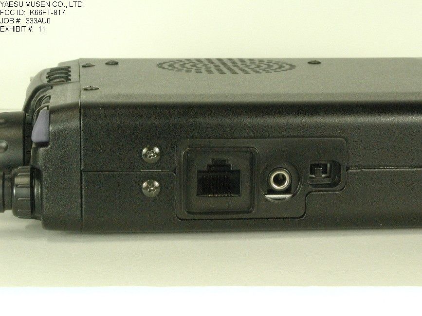
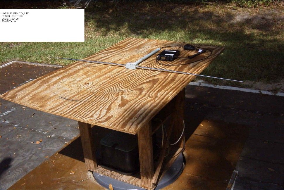
Document Text
Text extracted from the exhibit documents filed with the FCC. Open a document above to read the original.
Users Manual
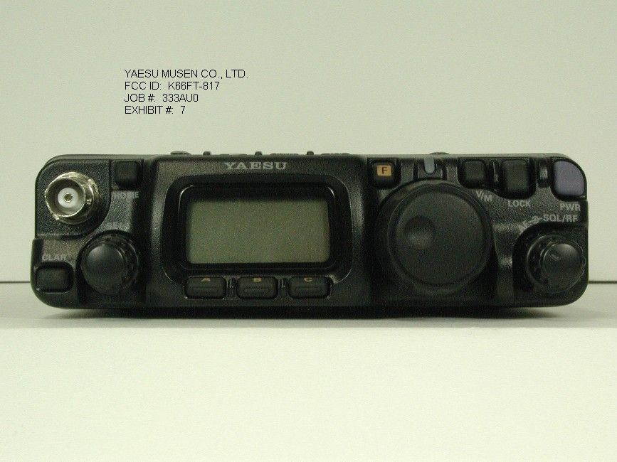
FT-817 O PERATING M ANUAL 1 Front Panel Control & Switches Front Panel Control & SwitchesFront Panel Control & Switches Front Panel Control & Switches (1) PWR Switch Press and hold in the PWR switch for one second to turn to the transceiver on or off. (2) AF Knob This (inner) VOL knob adjusts the receiver audio volume level presented to the speaker or external speaker. Clockwise rotation increases the volume level. (3) SQL/RF Knob In the USA version, this (outer) SQL/RF knob adjust the gain of the receiver’s RF and IF stage. Using Menu Selection 45, this control may be changed to function as a Squelch control, which may be used to silence background noise when no signal is present. In the other versions, its default setting is squelch control. (4) LOCK Key Pressing this key locks the so as to prevent accidental frequency change. (5) V/M Key Pressing this key switches frequency control between the VFO and Memory System. (6) TRANSMIT/BUSY Indicator This LED glows green when the squelch open, and turns red during transmit. (7) MAIN DIAL This is the main tuning dial for the transceiver. It is used both for frequency tuning as well as “Menu” setting in the transceiver. (8) F Key Pressing this key to changes the SEL knob which is selecting the FUNC key functions. Press and hold this key for one second to activate the menu function. (9) FUNC Keys These three keys select many of the most important operating features of the transceiver. When pressing the [ F ] key, the current function of that key appears above each of the [ A ], [ B ], [ C ] keys (along the bottom of the LCD); rotating the SEL knob scrolls the display through eleven rows of functions available for use via the [ A ], [ B ], [ C ] keys. The available features are shown in chart below. [ A ] Key[ B ] Key[ C ] Key 1 A/B Press the [ A ] key to switch between VFO-A and VFO-B on the display. A=B Press and hold the [ B ] key for 1/2 second to copy the contents of VFO-A into the VFO-B register, so that the two VFOs’ contains will be identical. SPL Press the [ C ] key to activates Split frequency operation between VFO-A and VFO-B. 2 MW Press and hold the [ A ] key for 1/2 second to transfer the contents of the VFO into a Memory register. MC Press the [ B ] key to designates the current Memory channel to be “skipped” during scanning. TAG Press the [ C ] key to select the display type (Frequency or Alpha-numeric Tag) during Memory operation. 3 STO Press the [ A ] key to store the contents of the VFO into a QMB register. RCL Press the [ B ] key to recall the QMB Memory. PMS Press the [ C ] key to activates the Programmable Memory Scan. 4 RPT Press the [ A ] key to select the direction of the uplink frequency shift (“–,” “+,” or simplex) during FM repeater operation. Press and hold the [ A ] key for 1/2 second to recall Menu #42 (for setting the shift frequency). REV Press the [ B ] key to reverse the transmit and receive frequency while working through a repeater. TON Press the [ C ] key to activate the CTCSS or DCS operation. Press and hold the [ C ] key for 1/2 second to recall Menu #48 (for selecting the CTCSS tone frequency). 5 SCN Press the [ A ] key to initiate scanning (in the direction of higher frequency). PRI Press the [ B ] key to activate the priority scan. DW Press the [ C ] key to activates the Dual Watch system. 6 SSMSCHART FT-817 O PERATING M ANUAL 2 Press the [ A ] key to activate the Spectrum Scope feature. Press and hold the [ A ] key for 1/2 second to recall Menu #43 (for selecting the sweep mode). Press the [ B ] key to activate Smart Search TM operation. Press the [ C ] key to initiate the Auto- Range Transponder mode. Press and hold the [ C ] key for 1/2 second to recall Menu #09 (for selecting the ARTS beep option). 7 IPO Press the [ A ] key to bypass the receiver preamplifier, thereby causing Intercept Point Optimization for improved characteristics. The IPO feature does not function on 144/430 MHz. AT T Press the [ B ] key to engage the receiver front-end attenuator, which will reduce all signals and noise by approximately 10 dB. The ATT feature does not function on 144/430 MHz. NAR Press the [ C ] key to activate the “Narrow” filter mode in the CW (optional YF-122C required) and SSB (optional YF-122S required) mode. On FM mode, it also select the low- deviation mode required for HF FM operation on 29 MHz. Press and hold the [ C ] key for 1/2 second to recall Menu #38 (for Enable/disable the optional filter). 8 NB Press the [ A ] key to activate the receiver’s IF noise Blanker. AGC Press the [ B ] key to select the recovery time ( F AST , S LOW , or A UTO ) for the receiver’s AGC system. – 9 PWR Press the [ A ] key to select the transmitter power output level ( L OW 1 , L OW 2 , L OW 3 , or H IGH ). MTR Press the [ B ] key to select the display function of the meter in the transmit mode (Power, ALC, SWR, or MOD indication). – 10 VOX Press the [ A ] key to enable the VOX (voice-operated transmitter switching system) in the SSB, AM, and FM modes. Press and hold the [ A ] key for 1/2 second to recall Menu #51 (for setting the VOX Gain level). BK Press the [ B ] key to activate CW Break-in operation. Press and hold the [ B ] key for 1/2 second to recall Menu #17 (for setting the CW Delay time). KYR Press the [ C ] key to activate the built-in Electronic Keyer. Press and hold the [ C ] key for 1/2 second to recall Menu #21 (for setting the Keyer speed). 11 CHG Press the [ A ] key to initiate the battery charging. Press and hold the [ A ] key for 1/2 second to recall Menu #11 (for selecting the Charging period). VTL Press the [ B ] key to display the current battery voltage. DSP Press the [ C ] key to switches display between Large Character and Small Character mode. *The Operating Function number in this column does not appear on the LCD. (10) BAND(DWN)/BAND(UP) Key Pressing one of these keys momentarily will cause the frequency to be moved up or down by one Frequency Band. The selections are available are: ... 1.8 MHz !…
Text truncated - open the document above for the full version.
Parts List/Tune Up Info
Alignment 1/10 YAESU MUSEN CO., LTD. FT-817 Alignment Local Oscillator Adjustment Reference Frequency Adjustment a. Connect a frequency counter to J5002 2pin (TP1047). b. Adjust the trimmer capacitor (TC5001) for 22.625000MHz +/- 5Hz on the frequency counter. c. Connect a RF millivoltmeter or an oscilloscope to the J5002 2pin (TP1047) and confirm that the output level is at least 70mVrms or 200mVp-p. PLL Adjustment VCO VCV Adjustment a. Connect a DC voltmeter to J2002 6pin (TP1007) and referring to the table below, tune the transceiver to each frequency listed. Then confirm that the correct voltage is present, or adjust the listed components for the required voltage. Tune to :Adjust / ConfirmFor 13.895MHzAdjust TC20034.5V +/- 0.1V 76.000MHzConfirmAt least 0.5V 32.995MHzAdjust TC20024.5V +/- 0.1V 13.900MHzConfirmAt least 0.8V 55.995MHzAdjust TC20014.5V +/- 0.1V 88.000MHzConfirmAt least 0.8V 153.995MHzAdjust L20104.5V +/- 0.1V 108.000MHzConfirmAt least 0.5V 469.995MHzAdjust L20114.5V +/- 0.1V 420.000MHzConfirmAt least 0.8V 1 st Local Output Level a. Connect a RF millivoltmeter to J2002 11pin and tune the transceiver to 28.000MHz. b. Confirm that the RF level is at least +5dBm or 400mVrms. PLL Unlock a. Connect a DC voltmeter to J2002 1pin (TP1001). b. When the reference input is not activated, the voltmeter shows less than 0.5V and “UNLOCK” is displayed on the LCD. c. When the reference input is activated, the voltmeter shows at least 3.5V and LCD displays as it normally should do. Alignment 2/10 YAESU MUSEN CO., LTD. PA Unit Adjustment Before alignment, set the mode on CW and tune the transceiver to 1.800MHz. Nothing should be connected to the CW Key Jack. Driver Stage Idling Current a. Remove the jumper connector J3005 and insert an ammeter. b. Press the PTT and adjust VR3001 for an indication of 28mA +/- 2mA on the ammeter. c. Disconnect the ammeter and reinstall the jumper connector at J3005 d. Remove the jumper connector J3006 and insert an ammeter. e. Press the PTT and adjust VR3002 for an indication of 18mA +/- 2mA on the ammeter. f. Disconnect the ammeter and reinstall the jumper connector at J3006. Final Stage Idling Current a. Connect an ammeter at each “13US” pin on PA Unit and Final Unit. If the “13US” line has already been connected by a wire, remove it and connect an ammeter. b. Turn both VR5401 and VR5402 fully to counterclockwise. c. Press the PTT and adjust VR5401 for an indication of 38mA +/- 2mA on the ammeter. d. Press the PTT and adjust VR5402 for an indication of 76mA +/- 4mA on the ammeter. e. Connect the “13US” line between PA unit and Final Unit again as it should be. Local Oscillator Adjustment 2 nd Local Adjustment a. Connect a RF millivoltmeter or an oscilloscope to Q1038 5pin (TP1067). b. Adjust T1024 and T1026 alternately for the maximum indication on the millivoltmeter or for the maximum amplitude on the oscilloscope. c. Confirm the indicated voltage is at least 120mVrms or 330mVp-p. 3ad Local Adjustment a. Connect a RF millivoltmeter or an oscilloscope to Q1055 5pin (T1087). b. Key the transceiver on CW mode and adjust T1021 for the maximum indication on the RF millivoltmeter. c. Confirm that the indicated voltage is at least 70mVrms or 200mVp-p. TX IF Adjustment CW TX IF Adjustment a. Tune the frequency to 1.8MHz band. Connect a RF millivoltmeter to J1002 terminated by 50ohm Alignment 3/10 YAESU MUSEN CO., LTD. dummy load. b. Key the transceiver and adjust T1020, T1012, and T1005 alternately for the maximum indication on the RF millivoltmeter. FM TX IF Adjustment a. Tune the frequency to 28MHz band. Connect a RF millivoltmeter to J1002 terminated by a 50ohm dummy load. b. Key the transceiver and adjust T1012 and T1013 alternately for the maximum indication on the RF millivoltmeter. c. Connect a frequency counter to TP1008. d. Key the transceiver on FM mode without microphone input. Adjust T1018 for 68.3300MHz +/- 50Hz. Carrier Balance Adjustment a. Terminate J1002 by a 50ohm dummy load and connect a spectrum analyzer or a RF millivoltmeter. b. Key the transceiver on USB mode in 28MHz band without microphone input. Adjust VR1001 for the maximum carrier suppression on the spectrum analyzer or for the minimum indication on the RF millivoltmeter. VHF TX BPF Adjustment a. Set the frequency at 145.995MHz. Connect RF millivoltmeter to J1002 terminated by a 50ohm dummy load. b. Key the transceiver on FM mode and adjust T1011, T1010, and T1009 alternately for the minimum indication on RF millivoltmeter. UHF TX BPF Adjustment a. Set the frequency at 439.995MHz. Connect a RF millivoltmeter to J1002 terminated by a 50ohm dummy load. b. Key the transceiver on FM mode and adjust TC1005, TC1004 and TC1002 alternately for the minimum indication on RF millivoltmeter. RX Adjustment PA Unit must be connected in RX adjustment. Signal Generator should not be connected to J1002 directly because DC voltage comes on there. Alignment 4/10 YAESU MUSEN CO., LTD. RX IF Adjustment Connect a signal generator to the antenna connector and a SINAD meter to the speaker jack. FM IF Adjustment a. Tune the transceiver to 51.995MHz. Inject a RF signal from a signal generator at 10dBu output, 1KHz AF FM modulation of 3.5KHz deviation. b. Adjust T1023, T1025, T1028, T1030 and T1034 alternately for the best SINAD sensitivity. c. Increase the output level of the signal generator up to 12dBu approximately and adjust T1023 and T1025 alternately for the best SINAD sensitivity. SSB IF Adjustment a. Connect a DC voltmeter to TP1063. b. Tune the transceiver to 51.995MHz. Inject a RF signal from a signal generator at 40dBu output. c. Adjust T1033 and T1029 alternately for the minimum indication on the DC voltmeter. Air-Band Reception Adjustment a. Connect a DC voltmeter to TP1063. b. Tune the transceiver to 128.00MHz on AM mode. Inject a RF signal from a signal generator at 40dBu output, 40% AM modulation of 400Hz AF. c. Adjust T1001, T1003 and T1007 for the minimum indication on the DC voltmeter. VHF Ban…
Text truncated - open the document above for the full version.
Test Report
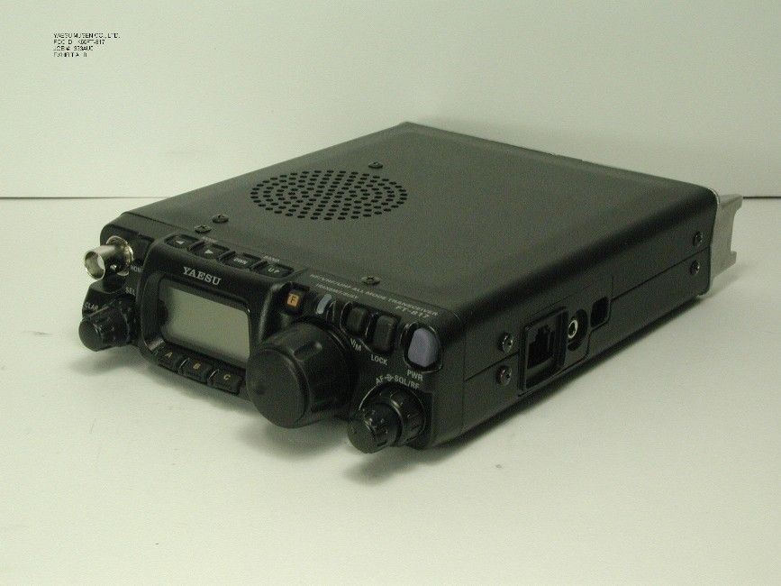
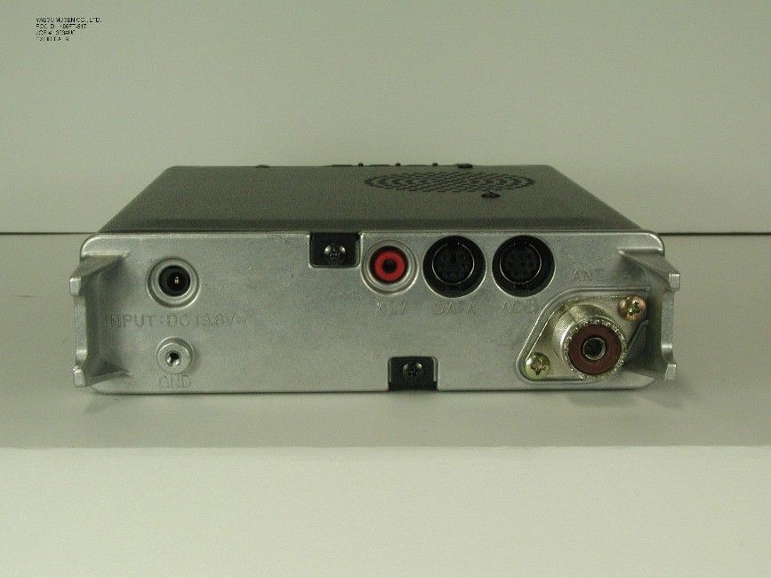
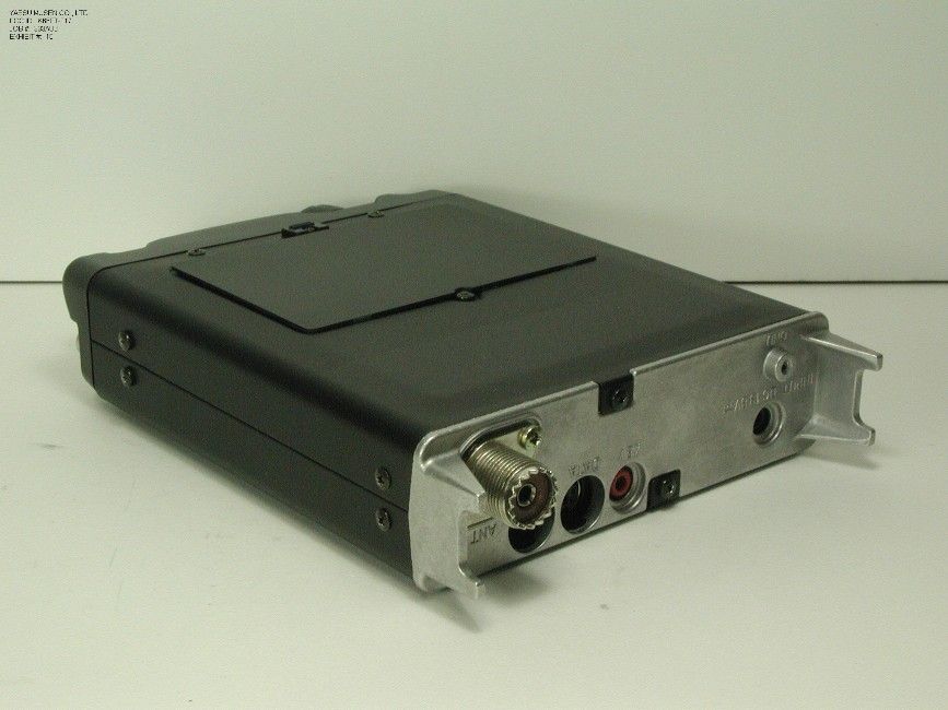
TABLE OF CONTENTS LIST APPLICANT: YAESU MUSEN CO., LTD. FCC ID: K66FT-817 TEST REPORT CONTAINING: PAGE 1......TEST EQUIPMENT LIST AND TEST PROCEDURE PAGE 2......TEST PROCEDURE CONTINUED PAGE 3-4....RADIATION INTERFERENCE TEST DATA PAGE 5......38 dB REJECTION RADIO EXHIBITS CONTAINING: EXHIBIT 1A...........STATEMENT PER 15.121(a) EXHIBIT 1B...........STATEMENTS PER 15.19 AND 15.21 EXHIBIT 2............BLOCK DIAGRAM EXHIBIT 3A...........SCHEMATIC - CONNECTION DIAGAM EXHIBIT 3B...........SCHEMATIC - MAIN UNIT EXHIBIT 3C...........SCHEMATIC - PLL-UNIT EXHIBIT 3D...........SCHEMATIC - PA-UNIT EXHIBIT 3E...........SCHEMATIC - PANEL-UNIT EXHIBIT 3F...........SCHEMATIC - VR-UNIT EXHIBIT 3G...........SCHEMATIC - REF-UNIT EXHIBIT 3H...........SCHEMATIC - FINAL-UNIT EXHIBIT 4A-4V........INSTRUCTION MANUAL EXHIBIT 5............SAMPLE OF FCC ID LABEL AND SKETCH OF LOCATION EXHIBIT 6............RADIATED TEST SETUP PHOTOGRAPH EXHIBIT 7............EXTERNAL PHOTO - FRONT VIEW EXHIBIT 8............EXTERNAL PHOTO - TOP VIEW EXHIBIT 9............EXTERNAL PHOTO - BACK VIEW EXHIBIT 10...........EXTERNAL PHOTO - BOTTOM VIEW EXHIBIT 11...........EXTERNAL PHOTO - SIDE VIEW EXHIBIT 12A-12B......INTERNAL PHOTO - COMPONENT VIEW EXHIBIT 13A-13C......INTERNAL PHOTO - COPPER VIEW EXHIBIT 14A-14J......CIRCUIT DESCRIPTION EXHIBIT 15A-15J......TUNING PROCEDURES APPLICANT: YAESU MUSEN CO., LTD. FCC ID: K66FT-817 REPORT #: T:\CUS\Y\YAE\333AU0\333AU0.RPT PAGE: TABLE OF CONTENTS LIST APPLICANT: YAESU MUSEN CO., LTD. FCC ID: K66FT-817 TEST EQUIPMENT LIST 1._X_Spectrum Analyzer: HP 8566B-Opt 462, S/N 3138A07786, w/ preselector HP 85685A, S/N 3221A01400, Quasi-Peak Adapter HP 8565OA, S/N 3303A01690 & Preamplifier HP 8449B-OPT H02, S/N 3008A00372 Cal. 10/17/99 2._X_Biconnical Antenna: Eaton Model 94455-1, S/N 1057 3.___Biconnical Antenna: Electro-Metrics Model BIA-25, S/N 1171 4._X_Log-Periodic Antenna: Electro-Metrics Model EM-6950, S/N 632 5.___Log-Periodic Antenna: Electro-Metrics Model LPA-30, S/N 409 6._X_Double-Ridged Horn Antenna: Electro-Metrics Model RGA-180, 1-18 GHz, S/N 2319 7.___18-26.3GHz Systron Donner Standard Gain Horn #DBE-520-20 8.___Horn 40-60GHz: ATM Part #19-443-6R 9.___Line Impedance Stabilization Network: Electro-Metrics Model ANS-25/2, S/N 2604 Cal. 2/9/00 10.___Temperature Chamber: Tenney Engineering Model TTRC, S/N 11717-7 11.___Frequency Counter: HP Model 5385A, S/N 3242A07460 Cal 10/6/99 12.___Peak Power Meter: HP Model 8900C, S/N 2131A00545 13._X_Open Area Test Site #1-3meters Cal. 12/22/99 14.___Signal Generator: HP 8640B, S/N 2308A21464 Cal. 9/23/99 15.___Signal Generator: HP 8614A, S/N 2015A07428 16.___Passive Loop Antenna: EMCO Model 6512, 9KHz to 30MHz, S/N 9706-1211 Cal. 6/10/00 17.___Dipole Antenna Kit: Electro-Metrics Model TDA-30/1-4, S/N 153 Cal. 11/24/99 18.___AC Voltmeter: HP Model 400FL, S/N 2213A14499 Cal. 9/21/99 19.___Digital Multimeter: Fluke Model 8012A, S/N 4810047 Cal 9/21/99 20.___Digital Multimeter: Fluke Model 77, S/N 43850817 Cal 9/21/99 21.___Oscilloscope: Tektronix Model 2230, S/N 300572 Cal 9/23/99 TEST PROCEDURE GENERAL: This report shall NOT be reproduced except in full without the written approval of TIMCO ENGINEERING, INC. RADIATION INTERFERENCE: The test procedure used was ANSI STANDARD C63.4-1992 using a HEWLETT PACKARD spectrum analyzer with a prese- lector. The bandwidth of the spectrum analyzer was 100 kHz with an appropriate sweep speed. The analyzer was calibrated in dB above a microvolt at the output of the antenna. The resolution bandwidth was 100KHz and the video bandwidth was 300KHz. The ambient temperature of the UUT was 80oC with a humidity of 76%. APPLICANT: YAESU MUSEN CO., LTD. FCC ID: K66FT-817 REPORT #: T:\CUS\Y\YAE\333AU0\333AU0.RPT PAGE #: 1 APPLICANT: YAESU MUSEN CO., LTD. FCC ID: K66FT-817 TEST PROCEDURE CONTINUED FORMULA OF CONVERSION FACTORS: The Field Strength at 3m was estab- lished by adding the meter reading of the spectrum analyzer (which is set to read in units of dBuV) to the antenna correction factor sup- plied by the antenna manufacturer. The antenna correction factors are stated in terms of dB. The gain of the Preselector was accounted for in the Spectrum Analyzer Meter Reading. Example: Freq (MHz) METER READING + ACF = FS 33 20 dBuV + 10.36 dB = 30.36 dBuV/m @ 3m ANSI STANDARD C63.4-1992 10.1.7 MEASUREMENT PROCEDURES: The unit under test was placed on a table 80 cm high and with dimensions of 1m by 1.5m. The table used for radiated measurements is capable of continuous rotation. When an emission was found, the table was rotated to produce the maximum signal strength. At this point, the antenna was raised and lowered from 1m to 4m. The antenna was placed in both the horizontal and vertical planes. The situation was similar for the conducted measurement except that the table did not rotate. The EUT was setup as described in ANSIC63.4-1992 with the EUT 40 cm from the vertical ground wall. APPLICANT: YAESU MUSEN CO., LTD. FCC ID: K66FT-817 REPORT #: T:\CUS\Y\YAE\333AU0\333AU0.RPT PAGE #: 2 APPLICANT: YAESU MUSEN CO., LTD. FCC ID: K66FT-817 NAME OF TEST: RADIATION INTERFERENCE RULES PART NUMBER: 15.109 REQUIREMENTS: 30 to 80 MHz: 40.0 dBuV/M @ 3 METERS 88 to 216 MHz: 43.5 dBuV/M 216 to 960 MHz: 46.0 dBuV/M ABOVE 960 MHz: 54.0 dBuV/M TEST RESULTS: A search was made of the spectrum from 30 to 1000 MHz and the measurements indicate that the unit DOES meet the FCC requirements. TEST DATA: TUNED EMISSION METER COAX FIELD FREQ. FREQUENCY READING LOSS A.C.F. STRENGTH MARGIN MHz MHz @ 3m dBuV dB dB dBuV/m@3m dB ANT. 33 TO 56 MHz BAND 43.00 222.60 9.50 1.20 12.58 23.28 22.72 V 55.00 123.30 5.60 0.80 10.72 17.12 26.38 V 55.00 246.60 12.10 1.20 13.28 26.58 19.42 H FM BAND 88.10 98.80 27.40 0.80 8.81 37.01 6.49 V 88.10 197.60 9.00 0.90 12.86 22.76 20.74 V 88.10 296.40 4.80 1.40 15.47 21.67 24.33 V 98.30 109.00 24.70 0.80 8.38 33.88 9.62 V 98.30 218.00 7.60 1.20 12.45 21.25 24.75 H 98.30 327.00 8.80 1.40 14.88 25.08 20.92 H 107.90 118.60 22.10 0.80 9.3…
Text truncated - open the document above for the full version.
Contact Information
Applicant
Masatoshi Muraishi(Engineering Division)
Test Firm
Timco Engineering, Inc.S Sanders
Technical Specifications
| # | Rule Parts | Frequency Range | Power Output |
|---|---|---|---|
| 5 | 15B | 420 MHz - 470 MHz | - |
Other Applications from Yaesu Musen Co., Ltd.
K660E180X10
Dec 01, 2025BLUETOOTH MICROPHONE
Equipment Class
DTS - Digital Transmission System
K6630673Y3D
Aug 01, 2024VHF FM Marine Transceiver
Equipment Class
CXX - Communications Rcvr for use w/ licensed Tx and CBs
K6630653Y3D
Aug 01, 2024VHF FM Marine Transceiver
Equipment Class
CXX - Communications Rcvr for use w/ licensed Tx and CBs
K6630683X30
Jan 10, 2023VHF FM Marine Transceiver
Equipment Class
TNF - Licensed Non-Broadcast Transmitter Held to Face
K6650033X30
Nov 18, 2020Airband Radio Transceiver
Equipment Class
TNF - Licensed Non-Broadcast Transmitter Held to Face