K66HX470SANon-broadcast Transceiver Held to Face
Yaesu Musen Co., Ltd.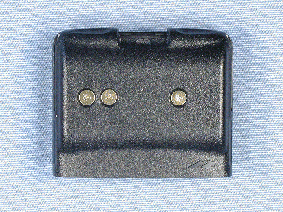
Click to zoom
Application Details
- Equipment Class
- FRF - Part 95 Family Radio Face Held Transmitter
- Date of Grant
- Jun 04, 2003
- Application Purpose
- Original Equipment
- Date of Application
- May 19, 2003
- Equipment Note
- Non-broadcast Transceiver Held to Face
- Frequency Range
- 462.63750000 - 467.63750000
- Company
- Yaesu Musen Co., Ltd.
- Country
- Japan
Documents & Files
Document Text
Text extracted from the exhibit documents filed with the FCC. Open a document above to read the original.
Users Manual
HX460S HX470S Submersible Dual Band Marine Portable Owner's Manual HX470S TABLE OF CONTENTS RF EXPOSURE SAFETY STATEMENT.......................................................................................2 FCC AND CANADA RADIO LICENSE INFORMATION...............................................................3 FCC NOTICE.................................................................................................................................5 1. GENERAL INFORMATION.......................................................................................................6 1.1 INTRODUCTION................................................................................................................6 2. ACCESSORIES.........................................................................................................................7 2.1 PACKING LIST....................................................................................................................7 2.2 OPTIONS...........................................................................................................................7 3. ABOUT THIS RADIO................................................................................................................8 3.1 ABOUT THE VHF MARINE BAND......................................................................................8 3.2 ABOUT FRS (Family Radio Service)..................................................................................8 3.3 ABOUT RECEIVE ONLY CHANNELS AND FREQUENCIES..........................................10 4. GETTING STARTED...............................................................................................................12 4.1 BATTERES AND CHARGERS.........................................................................................12 4.2 CONNECTING A GPS TO THE CD-25.............................................................................17 5. CONTROLS AND SWITCHES................................................................................................18 6. BASIC OPERATION...............................................................................................................22 6.1 INITIAL SETUP.................................................................................................................22 6.2 RECEPTION.....................................................................................................................23 6.3 TRANSMISSION...............................................................................................................24 6.4 NOAA WEATHER CHANNELS........................................................................................25 6.5 PRESET CHANNELS (P0 ~ P9).......................................................................................26 6.6 ENABLING S.O.S STROBE OPERATION.......................................................................27 7. ADVANCED OPERATION ON THE MARINE BAND.............................................................28 7.1 USA, CANADA, AND INTERNATIONAL CHANNELS......................................................28 7.2 MEMORY SCAN...............................................................................................................28 7.3 PRIORITY SCAN..............................................................................................................29 7.4 DUAL WATCH...................................................................................................................30 7.5 EMERGENCY CHANNEL 16............................................................................................30 7.6 CHANNEL 9......................................................................................................................30 7.7 OPERATING ON USA or CANADIAN 13, OR USA CHANNEL 67...................................30 7.8 OPERATING ON USA CHANNEL 67...............................................................................31 7.9 DIGITAL SELECTIVE CALLING.......................................................................................31 7.10 SIMPLEX/DUPLEX CHANEL USE.................................................................................32 8. CTCSS OPERATION ON THE FRS BAND............................................................................33 8.1 CTCSS CODE OPERATION............................................................................................33 9. BAROMETER AND SCRAMBLER OPERATION..................................................................34 9.1 BAROMETRIC PRESSURE METER................................................................................34 9.2 VOICE SCRAMBLER UNIT..............................................................................................34 10. OPERATING PRACTICE......................................................................................................35 10.1 EMERGENCY (CHANNEL 16 USE)...............................................................................35 10.2 CALLING ANOTHER VESSEL (CHANNEL 16 OR 9)....................................................35 10.3 OPERATING ON CHANNEL 13 AND 67........................................................................36 10.4 PROHIBITED COMMUNICATIONS................................................................................37 10.5 NOAA WEATHER ALERT TESTING..............................................................................37 11. RESETTING THE TRANSCEIVER’S MICROPROCESSOR..............................................38 12. CLONING..............................................................................................................................39 13. MENU (“SET”) MODE..........................................................................................................40 14. MAINTENANCE....................................................................................................................44 14.1 GENERAL....................…
Text truncated - open the document above for the full version.
Users Manual
HX470SPage 12 4. GETTING STARTED If the radio has never been used, or its charge is depleted, it may be charged by connecting the CD-25 Charger Cradle with the NC-72 battery charger, as shown in the illustration. If 12V DC power is available, the optional E-DC-19 DC Cable with 12 V Cigarette Lighter Plug or the optional E-DC-6 DC Cable may be used for charging the battery. The NC-72, E-DC-19 and E-DC-6 will charge a completely discharged FNB-80LI battery pack in about 3 hours. 4.1 BATTERIES AND CHARGERS The FNB-80LI is a high performance Lithium-Ion battery providing high ca- pacity in a very compact package. CAUTION To avoid risk of explosion and injury, FNB-80LI battery pack should only be removed, charged or recharged in non-hazardous environments. 4.1.1 BATTERY SAFETY Battery packs for your transceiver contain Lithium-Ion batteries. This type of battery stores a charge powerful enough to be dangerous if misused or abused, especially when removed from the transceiver. Please observe the following precautions: DO NOT SHORT BATTERY PACK TERMINALS: Shorting the terminals that power the transceiver can cause sparks, severe overheating, burns, and battery cell damage. If the short is of sufficient duration, it is possible to melt battery components. Do not place a loose battery pack on or near metal surfaces or objects such as paper clips, keys, tools, etc. When the battery pack is installed on the transceiver, the terminals that transfer current to the transceiver are not exposed. The terminals that are exposed on the battery pack when it is mounted on the transceiver are charging terminals only and do not constitute a hazard. DO NOT INCINERATE: Do not dispose of any battery in a fire or incinerator. The heat of fire may cause battery cells to explode and/or release danger- ous gases. HX470SPage 13 Battery Maintenance For safe and proper battery use, please observe the following: rBattery packs should be charged only in non-hazardous environments; rUse only STANDARD HORIZON-approved batteries; rUse only a STANDARD HORIZON, (a Marine Division of VERTEX STANDARD) approved charger. The use of any other charger may cause permanent damage to the battery. rFollow charging instructions provided with the chargers. rKeep the battery contacts clean. Battery Storage Store batteries in a cool place to maximize storage life. Since batteries are subject to self-discharge, avoid high storage temperatures that cause large self-discharge rates. After extended storage, a full recharge is recommended. Battery Recycling DO NOT PLACE USED BATTERIES IN YOUR REGULAR TRASH! LITHIUM-ION BATTERIES MUST BE COLLECTED, RECYCLED OR DIS- POSED OF IN AN ENVIRONMENTALLY SOUND MANNER. The incineration, land filling or mixing of nickel-cadmium batteries with the municipal solid waste stream is PROHIBITED BY LAW in most areas. Return batteries to an approved lithium-ion battery recycler. This may be where you purchased the battery. Contact your local waste management officials for other information regarding the environmentally sound collection, recycling and disposal of lithium-ion bat- teries. HX470SPage 14 4.1.2 BATTERY CHARGING If the radio has never been used, or its charge is depleted, it may be charged by connecting the CD-25 Charger Cradle with the NC-72 battery charger, as shown in the illustration. If 12V DC power is available, the optional E-DC-19 DC Cable with 12 V Cigarette Lighter Plug or the optional E-DC-6 DC Cable may be used for charging the battery. The NC-72, E-DC-19 and E-DC-6 will charge a completely discharged FNB-80LI battery pack in about 3 hours. NC-72, E-DC-6, or E-DC-19 4.1.3 BATTERY INSTALLATION/REMOVAL 1.Turn the transceiver off. 2.To install, insert the battery pack into the battery compartment on the back of the transceiver, then close the Battery Pack Latch until it locks in place with a “click.” 3.To remove, open the Battery Pack Latch on the bottom of the trans- ceiver, then slide the battery downward and out from the transceiver. HX470SPage 15 4.1.4 USING THE CD-25 CHARGER CRADLE 1.Turn the transceiver off. 2.Insert the DC plug from the NC-72 into the DC jack on the CD-25 rear panel, then plug the NC-72 into the AC line outlet. 3.Insert the HX470S (with the battery pack) into the CD-25; the antenna should be at the left side when viewing the charger from the front. 4.If the HX470S is inserted correctly, the Red “CHARGING” indicator will glow. A fully-discharged pack will be charged completely in approximately 3 hours. 5.The Red “CHARGING” indicator will blink when charging is nearing completion. 6.When charging is completed, the Red “CHARGING” indicator will disap- pear, and the Green “FULL” indicator will glow. Disconnect the pack from the CD-25, and unplug the NC-72 from the AC line outlet. 4.1.5 MOUNTING THE CD-25 ON THE VESSEL The CD-25 is designed to be surface or wall mounted on a vessel which can be connected to the charger and a GPS that supplies NMEA data for DSC Distress transmissions. If mounting on a vessel the CD-25 must be mounted in a location on the vessel that is directly shielded from rain or splashes of water. After the loca- tion is found mount the CD-25 using the supplied mounting screws. CD-25 Desktop Mount CD-25 Wall Mount HX470SPage 16 When using the HX470S/CD-25 on the vessel, be sure to secure the mount- ing band on the CD-25 so that it secures the HX470S so it will not fall out due to rough seas. See the illustration below. HX470SPage 17 4.2 CONNECTING A GPS TO THE CD-25 The CD-25 is supplied with a cable that is designed to be connected to any GPS that has an NMEA Output with the GLL, GGA, GNS, or RMC sen- tences. Check with the owner’s manual of the GPS to confirm this informa- tion. The NMEA input cable on the CD-25 contains two wires, uses are shown below. Blue – NMEA Input (Connects to NMEA Out of GPS) Green – NMEA Negative (Connects to NMEA Negative or battery Ground of GPS) If you have further inquires, please feel free to contact us at: Phone: (800) 767-…
Text truncated - open the document above for the full version.
Users Manual
HX470SPage 22 6. BASIC OPERATION 6.1 INITIAL SETUP 1.Install the belt clip on the transceiver according to the description in the box below, if desired. 2.Install the nylon carrying strap on the belt clip, if desired. 3.Install the battery pack on the transceiver (see section 4.1.3 “BATTERY INSTALLATION/REMOVAL”). NOTE: Water resistance of the transceiver is assured only when the battery pack is attached to the transceiver and MIC/SP rubber cap is installed in the MIC/SP jack. How to use the Quick Draw Belt Clip 1.Connect the hanger to the rear of the HX470S, with the notch pointing directly up, using the supplied screw (Figure 1). Use only the screw included with the clip to mount the clip to the back of the transceiver! 2.Clip the Quick Draw Belt Clip to your belt (Figure 2). 3.To install the HX470S into the Quick Draw Belt Clip, align the hanger with the Quick Draw Belt Clip and slide the HX470S into its slot until a click is heard. 4.To remove the HX470S from the Quick Draw Belt Clip, rotate the HX470S 180 degrees, then slide the transceiver out from the Quick Draw Belt Clip (Figure 3). Ò Ú Figure 3Figure 1Figure 2 HX470SPage 23 6.2 RECEPTION 1.Turn the POWER/VOLUME CONTROL knob clockwise to turn the trans- ceiver on. 2.Turn the SQUELCH CONTROL knob fully counterclockwise. This state is known as “Squelch Off.” 3.Turn up the POWER/VOLUME CONTROL knob until the noise or audio from the speaker is at a comfortable level. 4.Select the desired operating band among the VHF Marine band, FRS band, MURS band, FM band, AM band, and AIR band by pressing the [BAND] key repetitively to switch between the bands. 5.Turn the squelch control fully to the left so au- dio is heard. 6.Press the [p] or [q] key to select a channel or frequency that has no signal being received (no one is transmitting on the channel) 7.Slowly turn the SQUELCH CONTROL knob clockwise and stop immedi- ately after the noise disappears. This condition is known as the “Squelch Threshold.” If the knob is turned clockwise past this point, weak signals may not be received. No noise or no signal is heard until a signal is received that exceeds the squelch threshold. Sometimes, a slight ad- justment of the squelch threshold is needed, as some channels have a higher noise level than others. 8.Press the [SCAN] key momentarily; the HX470S will begin scanning to- ward a higher channel or frequency and will stop when it receives a signal strong enough to break through the squelch threshold. Press the [SCAN] key momentarily to channel the scanning. Refer to section 7.2 for programming channels into scan memory. 9.Please refer to section 16 for VHF Marine and section 3 for FRS and MURS channel assignments. 10.If necessary, press the LAMP key to turn on the display illumination. The lamp automatically turns off in about 5 seconds. 11.To “lock” the channel so that it is not accidentally changed, hold down the LAMP key for about three seconds. This locks the [p] and [q] keys and all the front panel controls except the [H/L], PTT and LAMP keys. The “ ” symbol will appear on the display to indicate that the keypad is locked. Hold down the LAMP key for about one second to unlock the keys. The “” symbol will disappear from the display.. HX470SPage 24 6.3 TRANSMISSION 1.Perform steps 1 through 7 of the RECEPTION discussion above. 2.Before transmitting, monitor the channel and make sure it is clear. THIS IS AN FCC REQUIREMENT! 3.For communications over short distances on the Marine band, press the [H/L] key until “L” is displayed on the LCD. This indicates Low power (approximately 1 watt). Note Transmitting on 1 watt prolongs battery life. Low power (1 watt) should be selected whenever possible. On the FRS band, the transmit power is fixed (0.5 Watt). 4.If using Low power is not effective, select Medium power (2.5 watts) or High power (5 watts) by pressing the [H/L] key until “M” (Medium power) or “H” (High power) is displayed. 5.When receiving a signal, wait until the incoming signal stops before trans- mitting. The transceiver cannot transmit and receive simultaneously. 6.Press the PTT (Push-To-Talk) switch to transmit. The “TX” indicator is displayed during transmission. 7.Speak slowly and clearly into the microphone. Hold the microphone about 1/2 to 1 inch away from your mouth. 8.When the transmission is finished, release the PTT switch. For an overview of VHF Marine and FRS band operating procedures refer to section 3. 6.3.1 TRANSMIT TIME - OUT TIMER (TOT) While the PTT switch is held down, transmission time is limited to 5 minutes. This prevents prolonged (unintentional) transmissions. About 10 seconds before automatic transmitter shutdown, a warning beep sounds from the speaker. The transceiver automatically switches to the receiving mode, even if the PTT switch is held down. Before transmitting again, the PTT switch must first be released, and then pressed again. This Time-Out-Timer (TOT) prevents a continuous transmission that would result from an accidentally stuck PTT switch. HX470SPage 25 6.4 NOAA WEATHER CHANNELS 1.To receive a NOAA weather broadcast, press the [WX] key. The trans- ceiver changes to the weather channel mode. This mode consists of a special preset memory bank containing the NOAA weather channels. 2.The transceiver will be set to the last used NOAA weather channel. Press the [p] or [q] key to change to other weather channels. 3.To exit from the weather channel mode, press the [WX] key. The trans- ceiver will revert to the channel you were using prior to switching to the weather channel mode. 6.4.1 NOAA WEATHER ALERT In the event of extreme weather disturbances such as storms and hurri- canes, NOAA (National Oceanic and Atmospheric Administration) sends a “weather alert” consisting of a 1050 Hz tone, followed by weather reports on the weather channels. The transceiver is capable of receiving this alert if the following is performed: 1.Program your area’s weather channels into the transceiver’s scan memory. Follow the same p…
Text truncated - open the document above for the full version.
Cover Letter(s)
Date: May 20, 2003 Federal Communications Commission Via: Electronic Filing Attention: Authorization & Evaluation Division Applicant: Vertex Standard Co., Ltd. Equipment: HX470S FCC ID: K66HX470SA FCC Rules: 2, 80, 95, Confidentiality Gentlemen: In view of the history associated with this radio, the Applicant respectively requests that this submission be accorded ‘first-in- line’ status. On behalf of the Applicant, enclosed please find Application Form 731, Engineering Test Report, documentation and filing fees, the whole as per the email of Stan Lyles (dated May 16, 2003). Please note the following: 1) Some of the documentation is preliminary, (still noting the original FCC IDENTIFIER) but will be changed to the new ID. 2) The deletion of MURS capability is, and will be achieved by a software change. All references to the MURS function will be deleted from the preliminary manual and documentation. 3) An explanatory cover letter is attached to the SAR report. As you are well aware, this situation is very serious and every effort to speed its Certification will be much appreciated. Sincerely yours, Morton Flom, P. Eng. enclosure(s) cc: Applicant MF/cva
External Photos
FCC ID: K66HX470SA Vertex Standard Co., Ltd. Front of EUT Rear of EUT FCC ID: K66HX470SA Vertex Standard Co., Ltd. Front of EUT Rear of EUT FCC ID: K66HX470SA Vertex Standard Co., Ltd. Left side of EUT Right side of EUT FCC ID: K66HX470SA Vertex Standard Co., Ltd. Top of EUT Bottom of EUT FCC ID: K66HX470SA Vertex Standard Co., Ltd. Rear side without battery pack Front of battery pack FCC ID: K66HX470SA Vertex Standard Co., Ltd. Rear of battery pack Microphone
ID Label/Location Info
HX470SHX470S LABEL DRAWING and LOCATIONLABEL DRAWING and LOCATION Vertex Standard Co., Ltd.Vertex Standard Co., Ltd. (1:1) (1:2) FCC ID Label drawing HX470S K66HX470SA Label location 511B-HX470S V HX470S K66HX470SA 511B-HX470S V
Internal Photos
FCC ID: K66HX470SA Vertex Standard Co., Ltd. Inside of EUT CNTL-UNIT in front case FCC ID: K66HX470SA Vertex Standard Co., Ltd. AF-UNIT in front case RF-UNIT in front case FCC ID: K66HX470SA Vertex Standard Co., Ltd. Inside of front case Inside of rear case FCC ID: K66HX470SA Vertex Standard Co., Ltd. Inside of microphone
Internal Photos
FCC ID: K66HX470SA Vertex Standard Co., Ltd. Side-A of CNTL-UNIT with LCD Side-A of CNTL-UNIT without LCD FCC ID: K66HX470SA Vertex Standard Co., Ltd. Side-B of CNTL-UNIT Front of LCD FCC ID: K66HX470SA Vertex Standard Co., Ltd. Rear of LCD Side-A of AF-UNIT FCC ID: K66HX470SA Vertex Standard Co., Ltd. Side-B of AF-UNIT Side-A of RF-UNIT with SW-UNIT FCC ID: K66HX470SA Vertex Standard Co., Ltd. Side-B of RF-UNIT with VCO-UNIT Side-B of RF-UNIT without VCO-UNIT FCC ID: K66HX470SA Vertex Standard Co., Ltd. VCO-UNIT in shield case Side-A of VCO-UNIT FCC ID: K66HX470SA Vertex Standard Co., Ltd. Side-B of VCO-UNIT Side-A of SW-UNIT FCC ID: K66HX470SA Vertex Standard Co., Ltd. Side-B of SW-UNIT
Operational Description
Circuit Description The HX470S consists of RF UNIT, CNTL UNIT, VCO UNIT and AF UNIT. The RF UNIT contains the receiver front end, PLL IC, power and switching circuits, and the VCO UNIT for transmit and receive local signal oscillation. The CNTL UNIT contains the CPU, and audio ICs, and the power circuitry for the LCD. The AF UNIT contains the IF, and audio ICs. Receiver Signal Flow The HX470S includes three receiver front ends, each opti- mized for a particular frequency range and mode combi- nation. Triplexer Signals between 0.5 and 1.8 MHz received at the antenna terminal pass through a first low-pass filter composed of L1041, L1001, C1203 and C1007. Received VHF bands signals, after passing through a low- pass filter to the VHF T/R switch circuit composed of di- ode switch D1033 (RLS135), D1034 (1SV307). Received UHF bands signals, after passing through a low- pass filter to the UHF T/R switch circuit composed of di- ode switch D1030 (RLS135) and D1031 (1SV307). VHF Bands Reception Received VHF bands signals pass through the Triplexer circuit, low-pass filter/high-pass filter circuit, VHF T/R switch circuit and protector diode D1002 (1SS362) before additional filtering by a band-pass filter prior to applica- tion to RF amplifier Q1002 (2SC5555). The amplified RF signal is pass through the band-pass filter to first mixer Q1006 (2SC5555). Meanwhile, VHF output from the VCO UNIT is amplified by Q1011 (2SC5374) and applied through diode T/R switch D1022 (DAN222) to mixer Q1006 as the first local signal. The 47.25 MHz (WFM: 45.8 MHz) intermediate frequency product of the mixer is delivered to the AF UNIT. The TUNE-voltage from the CPU on the CNTL UNIT is amplified by DC amplifier Q3014 (NJU7007F2) and ap- plied to varactors D1008 and D1010 (both HVC369B), D1007, D1009, D1011, D1012, D1013, and D1019 (all 1SV325) in the variable frequency band-pass filters. By changing the electrostatic capacitance of the varactors, optimum filter characteristics are provided for each spe- cific operating frequency. UHF Band Reception Received UHF bands signals pass through the Triplexer circuit, low-pass filter/high-pass filter circuit, UHF T/R switch circuit and protector diode D1001 (1SS362) before additional filtering by a band-pass filter prior to applica- tion to RF amplifier Q1001 (2SC5555). The amplified RF signal is pass through the band-pass filter, RF amplifier Q1003 (2SC5555) and band-pass filter to first mixer Q1005 (2SC5555). Meanwhile, UHF output from the VCO UNIT is amplified by Q1010 (2SC5374) and applied through di- ode T/R switch D1021 (DN222) to mixer Q1005 as the first local signal. The 47.25 MHz intermediate frequency product of the mixer is delivered to the AF UNIT. 0.5 - 1.8 MHz Reception Received MW signals pass through the Triplexer circuit, low-pass filter circuit, protector diode D1005 (1SS362) be- fore additional filtering by a band-pass filter prior to ap- plication to RF amplifier Q1004 (2SC4915). The amplified RF signal is pass through the band-pass filter to first mixer Q1007 (2SC4915). Meanwhile, MW output from the VCO UNIT is amplified by Q1012 to mixer Q1007 as the first local signal. The 47.25 MHz intermediate frequency product of the mixer is delivered to the AF UNIT. The TUNE voltage from the CPU on the CNTL UNIT is amplified by DC amplifier Q3014 and applied to varac- tors D1013 (HVR100) in the variable frequency band-pass filters. By changing the electrostatic capacitance of the var- actors, optimum filter characteristics are provided for each specific operating frequency. First Intermediate Frequency (Narrow FM / AM) The 47.25 MHz first intermediate frequency from first mix- ers is delivered from the RF UNIT to the AF UNIT through jacks J1003 and J2002. On the AF UNIT, the IF for AM and FM-narrow signals is passed through NAR/WIDE switch D2001 (DAP222) and 47.25 MHz monolithic crystal filter (MCF) XF2001 to narrow IF amplifier Q2002 (2SC4915) for input to pin 16 of Narrow IF IC Q2013 (TA31136FN) after amplitude limiting by D2002 (DA221). Meanwhile, a portion of the output of 11.7 MHz crystal X1001 on RF UNIT is multiplied fourfold by Q2005 (2SC4915) and Q2010 (2SC4154E) to provide the 46.8 MHz second local signal, applied to the Narrow IF IC. Within the IC, this signal is mixed with the 47.25 MHz first intermediate frequency signal to produce the 450 KHz sec- ond intermediate frequency. This second IF is filtered by ceramic filter CF2002 (ALFYM450F=K) and amplified by the limiting amplifier within the Narrow IF IC before quadrate detection by ce- ramic discriminator CD2001 (CDBM450C7). Circuit Description Demodulated audio is output from pin 9 of the Narrow IF IC through narrow mute analog switch Q2020 (2SJ364) and squelch gate Q2026 (2SJ364) before de-emphasis at Q2019 (DTC144EE). The resulting audio is amplified by AF amplifier Q2028 (TDA7233D) and output through MIC/EAR jack J2001 to internal speaker SP1001 or an external earphone. First Intermediate Frequency (Wide FM) The 45.8 MHz first intermediate frequency from first mix- ers is delivered from the RF UNIT to the AF UNIT through jacks J1003 and J2002. On the AF UNIT, the IF for Wide FM signals is passed through NAR/WIDE switch D2001 (DAP222) and IF amplifier Q2004 (2SC4915) and second mixer Q2009 (2SC4915). The 10.7 MHz intermediate frequency product of the mix- er is delivered to the 10.7 MHz ceramic filter CF2001 passed through NAR/WIDE switch D2002 (DAN222) for input to pin 16 of IF IC Q2013 after amplitude. Meanwhile, a portion of the output of 11.7 MHz crystal X1001 on RF UNIT is multiplied fourfold by Q2007 (2SC4915) to provide the 35.1 MHz second local signal, applied to the second mixer Q2009. Within the second mixer, this signal is mixed with the 45.8 MHz first inter- mediate frequency signal to produce the 10.7 MHz second intermediate frequency. Also, a portion of the output of 11.7 MHz crystal X1001 on RF UNIT is amplitude by Q2005 and Q2010 to provide the 11.7 MHz third local signal, applied to th…
Text truncated - open the document above for the full version.
Parts List/Tune Up Info
Alignment The HX470S has been carefully aligned at the factory for the specified performance across the marine, FRS, MURS, AIR, AM broadcast and FM broadcast bands. Realignment should therefore not be necessary except in the event of a component failure. All component replace- ment and service should be performed only by an autho- rized Standard Horizon representative, or the warranty policy may be voided. The following procedures cover the sometimes critical and tedious adjustments that are not normally required once the transceiver has left the factory. However, if damage occurs and some parts are replaced, realignment may be required. If a sudden problem occurs during normal oper- ation, it is likely due to component failure; realignment should not be done until after the faulty component has been replaced. We recommend that servicing be performed only by au- thorized Standard Horizon service technicians who are experienced with the circuitry and fully equipped for re- pair and alignment. Therefore, if a fault is suspected, con- tact the dealer from whom the transceiver was purchased for instructions regarding repair. Authorized Standard Horizon service technicians realign all circuits and make complete performance checks to ensure compliance with factory specifications after replacing any faulty compo- nents. Those who do undertake any of the following alignments are cautioned to proceed at their own risk. Problems caused by unauthorized attempts at realignment are not covered by the warranty policy. Also, Standard Horizon a division of the VERTEX STANDARD must reserve the right to change circuits and alignment procedures in the interest of improved performance, without notifying owners. Un- der no circumstances should any alignment be attempted unless the normal function and operation of the transceiv- er are clearly understood, the cause of the malfunction has been clearly pinpointed and any faulty components re- placed, and the need for realignment determined to be absolutely necessary. The following test equipment (and thorough familiarity with its correct use) is necessary for complete realignment. Correction of problems caused by misalignment resulting from use of improper test equipment is not covered under the warranty policy. While most steps do not require all of the equipment listed, the interactions of some adjustments may require that more complex adjustments be performed afterwards. Do not attempt to perform only a single step unless it is clearly isolated electrically from all other steps. Have all test equipment ready before beginning, and fol- low all of the steps in a section in the order presented. Required Test Equipment rRF Signal Generator with calibrated output level at 500 MHz rDeviation Meter (linear detector) rAF Millivoltmeter rSINAD Meter rInline Wattmeter with 5% accuracy at 500 MHz rRegulated DC Power Supply: adjustable from 6 to 17 VDC, 3A r50-ohm Non-reactive Dummy Load: 10W at 500 MHz rFrequency Counter: >0.1 ppm accuracy at 500 MHz rAF Signal Generator rDC Voltmeter: high impedance rVHF Sampling Coupler rAF Dummy Load: 8 ohm,…
Text truncated - open the document above for the full version.
Contact Information
Applicant
Masatoshi Muraishi(Engineering Division)
Technical Contact
M. Flom Associates, Inc.Morton Flom
[email protected]480-926-3100
3356 N. San Marcos Pl., Suite 107 · Chandler, Arizona · United States
Non-Technical Contact
M. Flom Associates, Inc.Morton Flom
[email protected]480-926-3100
Test Firm
M. Flom Associates, Inc.Morton Flom
Technical Specifications
| # | Rule Parts | Frequency Range | Power Output | Emission | Tolerance |
|---|---|---|---|---|---|
| 2 | 95B | 462.6375 MHz - 467.6375 MHz | 316.00 mW | 11K0F3E | 2.5 ppm |
Other Applications from Yaesu Musen Co., Ltd.
K660E180X10
Dec 01, 2025BLUETOOTH MICROPHONE
Equipment Class
DTS - Digital Transmission System
K6630673Y3D
Aug 01, 2024VHF FM Marine Transceiver
Equipment Class
CXX - Communications Rcvr for use w/ licensed Tx and CBs
K6630653Y3D
Aug 01, 2024VHF FM Marine Transceiver
Equipment Class
CXX - Communications Rcvr for use w/ licensed Tx and CBs
K6630683X30
Jan 10, 2023VHF FM Marine Transceiver
Equipment Class
TNF - Licensed Non-Broadcast Transmitter Held to Face
K6650033X30
Nov 18, 2020Airband Radio Transceiver
Equipment Class
TNF - Licensed Non-Broadcast Transmitter Held to Face