K66VX-110
Yaesu Musen Co., Ltd.
Click to zoom
Application Details
- Equipment Class
- CSR - Scanning Receiver
- Date of Grant
- Feb 21, 2000
- Application Purpose
- Original Equipment
- Date of Application
- Nov 30, 1999
- Frequency Range
- 140.00000000 - 174.00000000
- Company
- Yaesu Musen Co., Ltd.
- Country
- Japan
Documents & Files
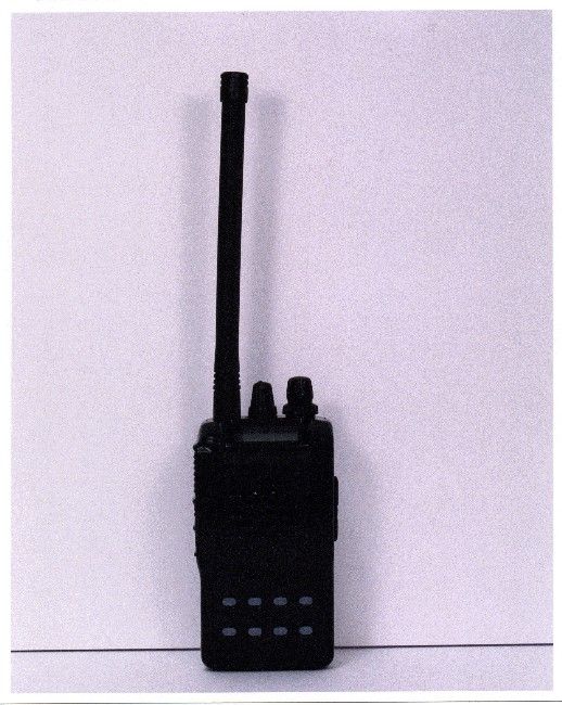
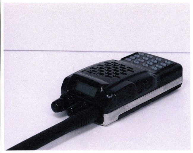
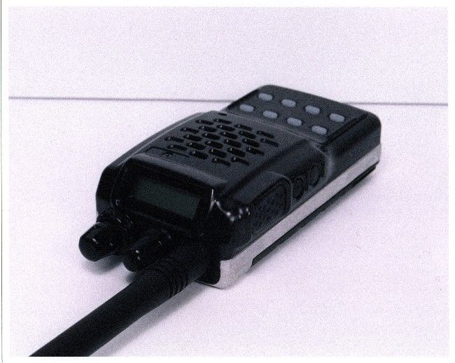
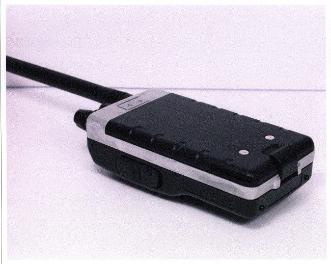
Document Text
Text extracted from the exhibit documents filed with the FCC. Open a document above to read the original.
Users Manual
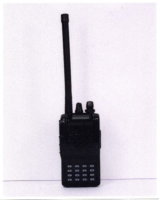
VX-150 OPERATING MANUAL1 The VX-150 is an ultra compact FM hand-held providing up to five watts of RF power and a wealth of new features for the 2m amateur band. The VX-150 accepts the same battery packs, and has rubber gasket seals around all external controls and connectors keep out dust and rain or spray, assuring years of reliable operation even in harsh environments. Sixteen multi-function keys provide the ultimate in programmability of 199 freely tunable memories and two VFOs. All memories store repeater shifts or separate tx/rx frequencies, CTCSS (Continuous Tone Controlled Squelch System) tone frequencies and tone encode/ decode selections with one instant-recall call channel memory and two special purpose memories for limited subband tuning/scanning. Busy channel band or selective memory scanning is provided along with priority channel monitoring; 1 MHz up/down stepping; ARS (automatic repeater shift) when tuned to repeater subbands, plus a top panel rotary dial for memory and frequency selection. The keypad serves as a DTMF encoder during transmission, and up to 9 DTMF memories can store 16 digits each for quick playback of commonly used numbers. The liquid crystal display shows seven frequency digits, memory selection, CTCSS tone frequency while setting*, page-received status when paged by a CTCSS tone, and includes a bargraph S/PO meter. Yaesu’s power saver system can be set by the operator for optimum sampling/standby ratio, or can be turned off for packet operation. And our new APO (Au- tomatic Power Off) system shuts off the transceiver to avoid dead batteries if you doze off or are called away unexpectedly. Operation under difficult conditions is simplified by a lamp button illuminating the display and backlit translucent keypad, diatonically assigned function-dependent keypad beeps. Please read this manual carefully to gain a clear understanding of the features of the VX- 150. *: Paging features require optional FVP-25. Introduction VX-150 OPERATING MANUAL2 Controls & Connectors TOP PANEL Å ANTENNA Jack This SMC jack accepts the supplied YHA-?? rub- ber flex antenna, or any other antenna designed to provide 50-ohm impedance on the 2m band. Ç VOL/OFF Control This control adjusts the volume of the receiver. Turn this control to the fully counterclockwise position (into the click stop) to turn the transceiver OFF. É DIAL Rotary Selector This 20-position detented rotary switch tunes the operating (or CTCSS tone) frequency or selects the memory channels, according to which function is selected by the keys on the front panel. This knob duplicates some of the functions of the up and down arrow keys for operating convenience. Ñ SQL Control This control sets the threshold level at which received signals (or noise) open the noise squelch. Set this control from counterclockwise just to the point where noise is si- lenced (and the BUSY/TX indicator on the front panel is off) when the channel is clear. Ö BUSY/TX Indicator Lamp This LED indicator glows green when the noise squelch is open during reception, and red when transmitting. Ü LCD (Liquid Crystal Display) The display shows the selected operating conditions as indicated in the following dia- gram: S- and TX Power Meter Auto Power OFF Active LOCK Feature Active LOW Power Alt Key Active Memory Number or VFO Selection Tone Encoder/Squelch Enabled Digital Coded Squelch DTMF Memory Mode Memory Skip BELL Priority Channel Scanning Repeater Shift Memory Mode Frequency VX-150 OPERATING MANUAL3 Controls & Connectors SIDE PANELS Å PTT Button Press and hold this (Push-to-Talk) button to transmit. The BUSY/TX indicator glows red while transmitting. Ç Monitor (Burst) Button In the USA version, this button opens the squelch momentarily without disturbing the setting of the SQL control. In the European version, this button activates the 1750 Hz Burst tone generator. É LAMP Button Press this button to illuminate the display and keypad when necessary. Ö MIC/EAR Jack This four-conductor miniature jack provides connection points for microphone audio, earphone audio, PTT, and ground. Ü EXT DC This coaxial DC jack allows connection to an external DC power source (6.0-16V DC). The center pin of this jack is the Positive (+) line. VX-150 OPERATING MANUAL4 FRONT PANELS Å Speaker The internal speaker is located directly below the display. Ç Mic The internal microphone is located at the bottom right-hand corner of the speaker. É Keypad These sixteen keys select the various operating features of the transceiver during re- ception, and generate DTMF (Dual Tone Multi Frequency) tone pairs during transmis- sion. One or two beeps will sound whenever one of the keys is pressed (if the beeper is active). The labels on the faces of the keys indicate their primary functions, while the labels above fifteen of the keys indicate alternate functions, which are activated by pressing the [ F/W ] key first, and then another key within five seconds. When referring to alternate key functions in this manual, we show the alternate key label followed by the primary label in parentheses ( ). Primary key functions are referred to by the labels on the keyfaces. Remember to press the [ F/W ] key first (momentarily, unless otherwise indicated) when you want to use an alternate key function. All key functions are described in the “Op- eration” section, and summarized on the “VX-150 Operator’s Quick Reference Card.” Controls & Connectors VX-150 OPERATING MANUAL5 ACCESSORIES SUPPLIED WITH THE VX-150 FNB-V577.2 V, 1100 mAh Ni-Cd Battery Pack FC-72A/B/C/F/UBattery Chareger Belt Clip Hand Strap Antenna Operating Manual Warranty Card AVAILABLE OPTIONS FOR YOUR VX-150 FNB-V577.2 V, 1100 mAh Ni-Cd Battery Pack FNB-627.2 V, 700 mAh Ni-Cd Battery Pack FBA-25Compact Dry Cell Battery Case for 6 AA-size cells NC-72A117 VAC Compact Wall Charger for FNB-14 NC-72B220-234 VAC Compact Wall Charger for FNB-14 NC-72C117 VAC Compact Wall Charger for FNB NC-72U220-234 VAC Compact Wall Charger for FNB N…
Text truncated - open the document above for the full version.
Attestation Statements
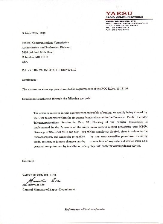
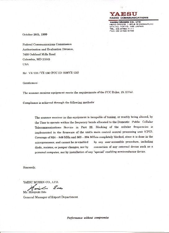
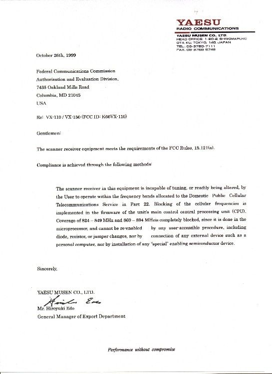
APPLICANT: YAESU MUSEN CO., LTD. FCC ID: K66VX-110 This is to confirm that the applicant will add the following statement to Page 37 of their user’s manual: 1. Changes or modifications to this device not expressly approved by Yaesu Musen could void the user’s authority to operate this device. 2. This devices complies with part 15 of the FCC Rules. Operation is subject to the following two conditions: (1) this device may not cause harmful interference, and (2) this device must accept any interference received, including interference that may cause undesired operation. 3. The scanning receiver in this equipment is incapable of tuing or readly being altered by the user to operate within the frequency bands allocated to the Domestic Pulblic Cellular Telecommunications Service in Part 22.
Attestation Statements
APPLICANT: YAESU MUSEN CO., LTD. FCC ID: K66VX-110 This is to confirm that the applicant will add the following statement to Page 37 of their user’s manual: 1. Changes or modifications to this device not expressly approved by Yaesu Musen could void the user’s authority to operate this device. 2. This devices complies with part 15 of the FCC Rules. Operation is subject to the following two conditions: (1) this device may not cause harmful interference, and (2) this device must accept any interference received, including interference that may cause undesired operation. 3. The scanning receiver in this equipment is incapable of tuing or readly being altered by the user to operate within the frequency bands allocated to the Domestic Pulblic Cellular Telecommunications Service in Part 22.
Test Report
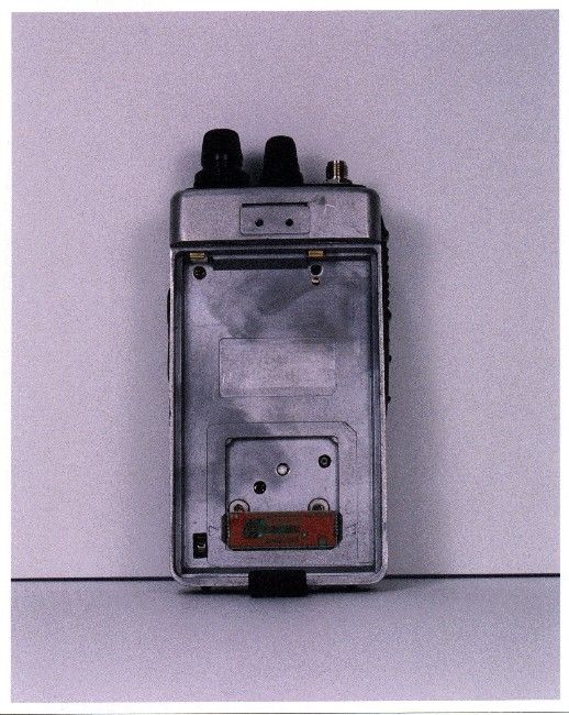
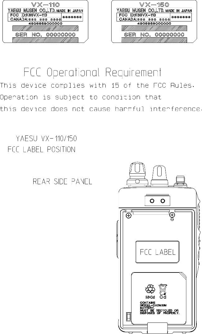
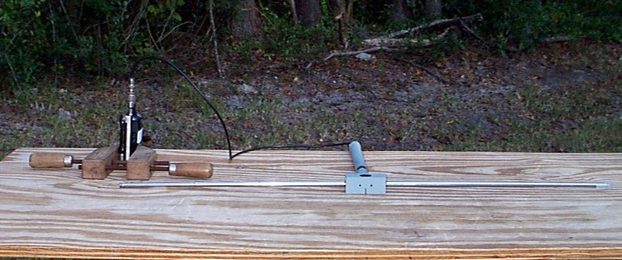
TABLE OF CONTENTS LIST APPLICANT: YAESU MUSEN CO., LTD. FCC ID: K66VX-110 TEST REPORT CONTAINING: PAGE 1......TEST PROCEDURE PAGE 2......TEST PROCEDURE & CIRCUIT DESCRIPTION PAGE 3......RADIATION INTERFERENCE TEST DATA PAGE 4......38 dB Rejection Ratio EXHIBITS CONTAINING: EXHIBIT 1.......POWER OF ATTORNEY LETTER EXHIBIT 2.......STATEMENT PER 15.121(a) EXHIBIT 3.......BLOCK DIAGRAM EXHIBIT 4A......SCHEMATIC - MAIN EXHIBIT 4B......SCHEMATIC - VR UNIT EXHIBIT 4C......SCHEMATIC - SW UNIT EXHIBIT 5.......INSTRUCTION MANUAL EXHIBIT 6.......SAMPLE OF FCC ID LABEL AND SKETCH OF LOCATION EXHIBIT 7.......RADIATED TEST SETUP PHOTOGRAPH EXHIBIT 8.......EXTERNAL PHOTO - FRONT SIDE OF 16 BUTTON EXHIBIT 9.......EXTERNAL PHOTO - FRONT SIDE OF 8 BUTTON EXHIBIT 10......EXTERNAL PHOTO - TOP SIDE OF 16 BUTTON EXHIBIT 11......EXTERNAL PHOTO - TOP SIDE OF 8 BUTTON EXHIBIT 12......EXTERNAL PHOTO - BACK SIDE EXHIBIT 13......EXTERNAL PHOTO - BACK SIDE WITH BATTERY COVER OFF EXHIBIT 14......INTERNAL PHOTO - COMPONENT SIDE EXHIBIT 15......INTERNAL PHOTO - COPPER SIDE APPLICANT: YAESU MUSEN CO., LTD. FCC ID: K66VX-110 REPORT #: T:\CUS\Y\YAE\YAE470A9\YAE470A9.RPT PAGE: TABLE OF CONTENTS LIST APPLICANT: YAESU MUSEN CO., LTD. FCC ID: K66VX-110 TEST EQUIPMENT LIST 1. Spectrum Analyzer: Hewlett Packard 8566B - Opt 462, w/ preselector 85685A, & Quasi-Peak Adapter HP 8565OA, & HP 8449B - OPT H02 Cal. 10/17/99 2. Signal Generator, Hewlett Packard 8640B, cal. 9/23/99 3. Signal Generator, HP 8614A Serial No.2015A07428 cal. 5/27/99 4. EMCO Model No. 6512 Passive Loop 9KHz to 30MHz 5. Eaton Biconnical Antenna Model 94455-1 20-200 MHz Serial No. 0997 Cal. 9/30/99 6. Electro-Metric Log-Periodic Model No. EM-6950 Ser#632 9/18/99 7. Electro-Metric Dipole Kit, 20-1000 MHz, Model TDA-30 10/31/98 8. Electro-Metric Horn 1-18 GHz, Model RGA-180, Cal. 4/27/99 9. Systron Donner Horn 18-26.3GHz Model DBE-520-20 7/14/99 10. Systron Donner Horn 26.5-40.2GHz Model DBD-520-20 7/14/99 11. ATM Horn 40-60GHz Part #19-443-6R 9/15/99 12. Electro-Metric Antennas Model TDA-30/1-4,Cal. 10/15/98 13. Electro-Metric Line Impedance Stabilization Network Model No. EM-7821, Serial No. 101; 100KHz-30MHz 50uH. Cal.11/19/98 14. Electro-Metric Line Impedance Stabilization Network Model No. EM-7820, Serial No. 2682; 10KHz-30MHz 50uH. Cal. 11/19/98 15. Special low loss cable was used above 1 GHz 16. Tenney Temperature Chamber 17. AC Voltmeter, HP 400FL, Serial No 2213A14499. Cal. 9/21/99 18. Digital Multimeter, Fluke 8010A/12A, Serial No. 4810047. Cal 9/21/99 19. Digital Multimeter, Fluke 77, Serial No. 43850817. Cal 9/21/99 20. Oscilloscope, Tektronix 2230, Serial No. 300572. Cal 9/23/99 21. Frequency Counter, HP 5385A, Serial No. 3242A07460. Cal 10/6/99 TEST PROCEDURE GENERAL: This report shall NOT be reproduced except in full without the written approval of TIMCO ENGINEERING, INC. RADIATION INTERFERENCE: The test procedure used was ANSI STANDARD C63.4-1992 using a HEWLETT PACKARD spectrum analyzer with a prese- lector. The bandwidth of the spectrum analyzer was 100 kHz with an appropriate sweep speed. The analyzer was calibrated in dB above a microvolt at the output of the antenna. The resolution bandwidth was 100KHz and the video bandwidth was 300KHz. The ambient temperature of the UUT was 80oC with a humidity of 76%. FORMULA OF CONVERSION FACTORS: The Field Strength at 3m was estab- lished by adding the meter reading of the spectrum analyzer (which is set to read in units of dBuV) to the antenna correction factor sup- plied by the antenna manufacturer. The antenna correction factors are stated in terms of dB. The gain of the Preselector was accounted for in the Spectrum Analyzer Meter Reading. Example: Freq (MHz) METER READING + ACF = FS 33 20 dBuV + 10.36 dB = 30.36 dBuV/m @ 3m REPORT #: T:\CUS\Y\YAE\YAE470A9\YAE470A9.RPT PAGE #: 1 TEST PROCEDURES CONTINUED APPLICANT: YAESU MUSEN CO., LTD. FCC ID: K66VX-110 ANSI STANDARD C63.4-1992 10.1.7 MEASUREMENT PROCEDURES: The unit under test was placed on a table 80 cm high and with dimensions of 1m by 1.5m. The table used for radiated measurements is capable of continuous rotation. When an emission was found, the table was rotated to produce the maximum signal strength. At this point, the antenna was raised and lowered from 1m to 4m. The antenna was placed in both the horizontal and vertical planes. The situation was similar for the conducted measurement except that the table did not rotate. The EUT was setup as described in ANSIC63.4-1992 with the EUT 40 cm from the vertical ground wall. CIRCUIT_DESCRIPTION: In the receive mode the signal comes in on the receive antenna to the double tuned circuit to the super-regenerative detector Q-3, where the audio is detected. From Q-3 the audio goes to the volume resistor R15 to the input to the three(3) stage audio amplification, Q1, Q4 & Q5. Q5 drives the audio output transform- er T3 which is connected to the speaker. ANTENNA_AND_GROUND_CIRCUITRY This unit makes use of a external 5 inch antenna. The antenna is inductively coupled. This unit is powered from a 9.0V battery. No ground connection is provided. The unit relies on the ground tract of the printed circuit board. APPLICANT: YAESU MUSEN CO., LTD. FCC ID: K66VX-110 REPORT #: T:\CUS\Y\YAE\YAE470A9\YAE470A9.RPT PAGE #: 2 APPLICANT: YAESU MUSEN CO., LTD. FCC ID: K66VX-110 NAME OF TEST: RADIATION INTERFERENCE RULES PART NUMBER: 15.109 REQUIREMENTS: 30 to 80 MHz: 40.0 dBuV/M @ 3 METERS 88 to 216 MHz: 43.5 dBuV/M 216 to 960 MHz: 46.0 dBuV/M ABOVE 960 MHz: 54.0 dBuV/M TEST RESULTS: A search was made of the spectrum from 30 to 1000 MHz and the measurements indicate that the unit DOES meet the FCC requirements. TEST DATA: TUNED EMISSION METER COAX FIELD FREQ. FREQUENCY READING LOSS A.C.F. STRENGTH MARGIN MHz MHz @ 3m dBuV dB dB dBuV/m@3m dB ANT. 140.02 118.39 11.50 0.80 9.32 21.62 21.88 H 153.52 131.88 10.50 0.80 13.90 25.20 18.30 V 162.48 141.00 10.00 0.80 16.90 27.70 15.80 H 173.98 152.33 6.00 0.90 16.83 23.73 19.77 V SAMP…
Text truncated - open the document above for the full version.
Contact Information
Applicant
Masatoshi Muraishi(Engineering Division)
Technical Contact
Timco Engineering, Inc.S. S. Sanders
[email protected]888-472-2424
P.O. Box 370 · Newberry, Florida · United States
Non-Technical Contact
Timco Engineering, Inc.Sharon A Hoffman
[email protected]888-472-2424
Test Firm
Timco Engineering, Inc.Sid Sanders
Technical Specifications
| # | Rule Parts | Frequency Range | Power Output |
|---|---|---|---|
| 1 | 15B | 140 MHz - 174 MHz | - |
Other Applications from Yaesu Musen Co., Ltd.
K660E180X10
Dec 01, 2025BLUETOOTH MICROPHONE
Equipment Class
DTS - Digital Transmission System
K6630673Y3D
Aug 01, 2024VHF FM Marine Transceiver
Equipment Class
CXX - Communications Rcvr for use w/ licensed Tx and CBs
K6630653Y3D
Aug 01, 2024VHF FM Marine Transceiver
Equipment Class
CXX - Communications Rcvr for use w/ licensed Tx and CBs
K6630683X30
Jan 10, 2023VHF FM Marine Transceiver
Equipment Class
TNF - Licensed Non-Broadcast Transmitter Held to Face
K6650033X30
Nov 18, 2020Airband Radio Transceiver
Equipment Class
TNF - Licensed Non-Broadcast Transmitter Held to Face