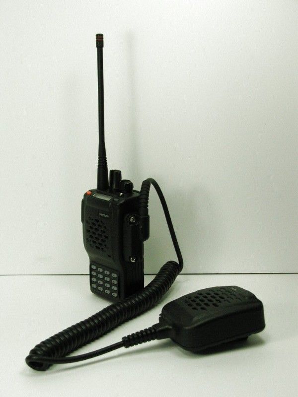
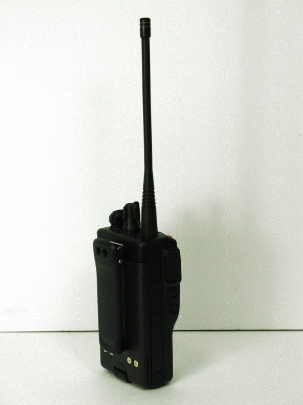
K66VX-800U-2UHF/FM HAND HELD TRANCEIVER
Yaesu Musen Co., Ltd.
Click to zoom
Application Details
- Equipment Class
- TNF - Licensed Non-Broadcast Transmitter Held to Face
- Date of Grant
- Sep 19, 2000
- Application Purpose
- Original Equipment
- Date of Application
- Aug 15, 2000
- Equipment Note
- UHF/FM HAND HELD TRANCEIVER
- Frequency Range
- 421.00000000 - 450.00000000
- Company
- Yaesu Musen Co., Ltd.
- Country
- Japan
Documents & Files
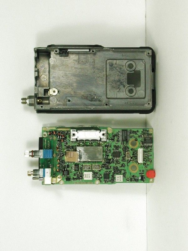
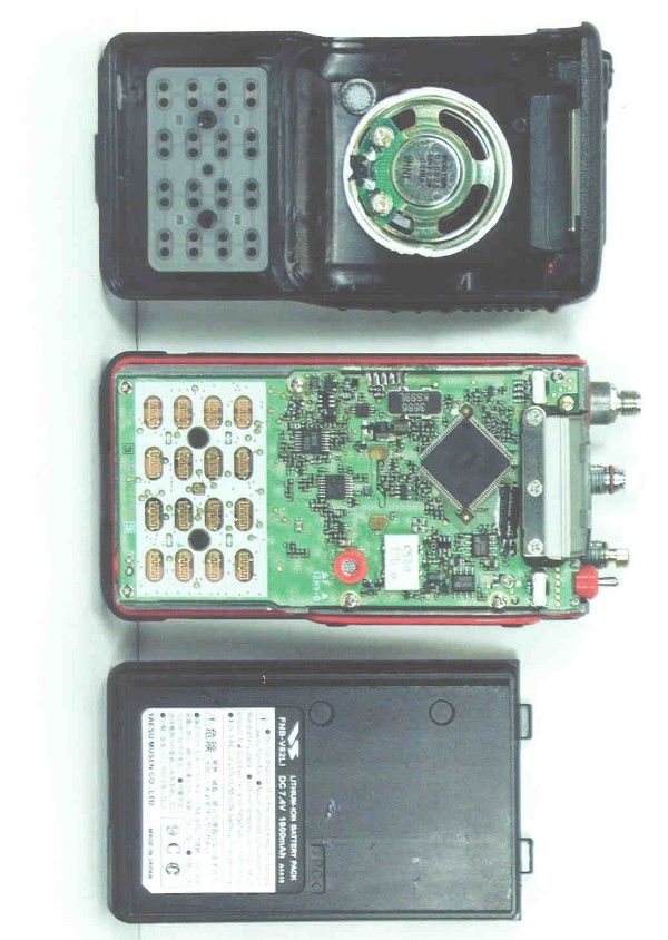
Document Text
Text extracted from the exhibit documents filed with the FCC. Open a document above to read the original.
Users Manual
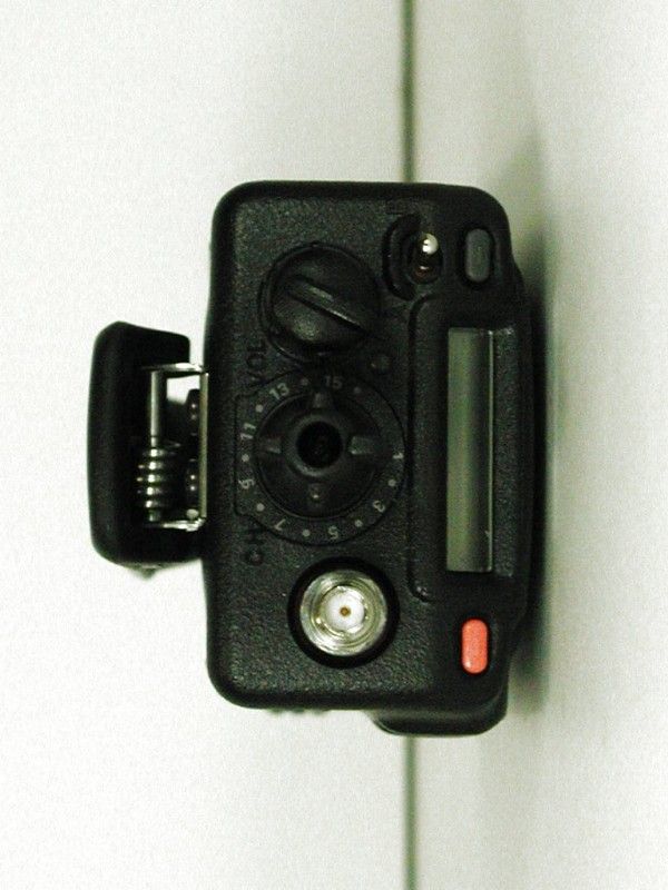
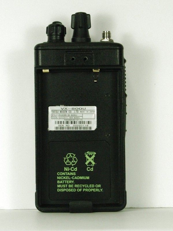
VX-800U Operating Manual 1 VX-800U Operating Manual 1,Controls & Connectors LED Indicator Glows Green: Scan active Blinks Green: Busy Channel (or SQL off) Glows Red: Transmit Blinks Red: Battery Voltage is low Antenna Jack PTT (Push to Talk) Switch Monitor Button Lamp Button CH (Channel) Selector VOL/PWR Knob LCD SEL1 KEY (Left) SEL2 KEY (Right) Toggle SW MIC/SP Jack (External MIC/SP) Speaker Main Microphone Sub Microphone (Noise Canceling Microphone) Battery Pack Latch 16-Button DTMF Keypad (16-key version only) 2,Before You Begin Battery Pack Installation and Removal r To install the battery, hold the transceiver with your left hand, so your palm is over the speaker and your thumb is on the top of the belt clip. Insert the battery pack into the battery compartment on the back of the radio while tilting the Belt Clip outward, then close the Battery Pack Latch until it locks in place with a “Click.” r To remove the battery, turn the radio off and remove any protective cases. Open the Battery Pack latch on the bottom of the radio, then slide the battery downward and out from the radio while unfolding the Belt Clip. Caution!: Do not attempt to open any of the rechargeable Ni-Cd packs, as they could explode if accidentally short-circuited. Low Battery Indication r As the battery discharges during use, the voltage gradually becomes lower. When the battery voltage reaches 6.0 volts, substitute a freshly charged battery and recharge the depleted pack. The TX/BUSY indicator on the top of the radio will blink red when the battery voltage is low. r Avoid recharging Ni-Cd batteries often with little use between charges, as this can degrade the charge capacity. We recommend that you carry an extra, fully- charged pack with you so the operational battery may be used until depletion (this “deep cycling” technique promotes better long-term battery capacity). 3,Operation VX-800U Operating Manual 2 Preliminary Steps r Install a charged battery pack onto the transceiver, as described previously. r Screw the supplied antenna onto the Antenna jack. Never attempt to operate this transceiver without an antenna connected. r If you have a Speaker/Microphone, we recommend that it not be connected until you are familiar with the basic operation of the VX-800. Operation Quick Start r To turn the top panel’s VOL/PWR knob clockwise to turn on the radio on. r Pull and turn the top panel’s CH selector knob to choose the desired operating channel. A channel number or channel name will appear on the LCD. r Rotate the VOL/PWR knob to set the volume level. If no signal is present, press and hold the Monitor button (the center button on the left side) more than 2 seconds; background noise will now be heard, and you may use this to set the VOL/PWR knob for the desired audio level. Press and hold the Monitor button more than 2 seconds (or press the Monitor button twice) to quiet the noise and resume normal (quiet) monitoring. r To transmit, press and hold the PTT switch. Speak into the microphone area of the front panel grille (lower right-hand corner) in a normal voice level. To return to the Receive mode, release the PTT switch. r Press the top panel’s SEL1/SEL2 button to active one of the preprogrammed functions, which may have been enabled at the time of programming by the dealer. See the next section for details regarding the available features. r Switch the top panel’s Toggle SW position to active one of the preprogrammed functions, which may have been enabled at the time of programming by the dealer. There are three positions of [A (left)], [B (center)] and [C (right)] in the toggle switch. See the next section for details regarding the available features. r Press the DTMF keys on the telephone keypad to send DTMF tones.(16-key version only) r If a Speaker/Microphone is available, remove the plastic cap and its two mounting screws from the right side of the transceiver, then make the connector of the Speaker/Microphone touch; secure the connector pin using the screw supplied with the Speaker/Microphone. Hold the speaker grille up next to your ear while receiving. To transmit, press the PTT switch on the Speaker/Microphone, just as you would on the main transceiver’s body. Note: Save the original plastic cap and its mounting screws. They should be re-installed when not using the Speaker/Microphone. 4,KEY and TOGGLE Functions VX-800 have the [SEL1], [SEL2], [MON], [LAMP] Key, ([A], [B], [C], [D] Key: only 16-key version) and Toggle SW. The Key and SW function can be customized, via programmed by YAESU dealer, to meet your communications requirements. Some features may require the purchase and installation of optional internal accessories. The possible KEY and SW programming features are illustrated below. [SEL1] , [SEL2], [MON], [LAMP],[A], [B], [C] and [D] Key Monitor (Generally, it sets to MON Key) Lamp (Generally, it sets to LAMP Key) Channel Scan VX-800U Operating Manual 3 Dual Watch High/Low Power Talk Around TX Save Disable Encryption Disable (only, when using DTMF/Encryption Unit) Follow-Me DW Group Up Group Down Channel Up Channel Down SET Mode Call/Reset (only, when using DTMF/Encryption Unit) Speed Dial (only, when using DTMP/Encryption Unit) Emergency (only, when using DTMF/Encryption Unit) LCD Invert TOGGLE Switch Channel Scan Dual Watch High/Low Power Talk Around TX Save Disable Encryption Disable (only, when using DTMF/Encryption Unit) Follow-Me Scan Lock LCD Invert 5,Understanding Radio Waves Radio waves travel from one point to another by several different means. The general term for these methods of wave travel is “propagation”. You may know that “shortwave” signals can be propagated over distances of several thousand miles by reflection off of the upper regions of the atmosphere. Your hand-held transceiver, on the other hand, operates on the so-called VHF (Very-High Frequency) band. On this band, radio waves usually do not reflect off of the atmosphere. Instead, the radio waves behave almost as light:…
Text truncated - open the document above for the full version.
Cover Letter(s)
849 NW State Road 45 • P. O. Box 370 • Newberr y, Florida 32669 USA Telephone (352) 472-5500 • (888) 472-2424 • FAX (352) 472-2030 • email: [email protected] 8/21/00 Federal Communications Commission Authorization and Evaluation Division 7435 Oakland Mills Road Columbia, MD 21046 REF: YAESU MUSEN CO. LTD.’S FCC ID: K66VX-800U-2 Confirmation #: EA98504 To Whom It May Concern: When we submitted the application for approval for the above mentioned FCC Identifier, we inadvertantly entered the wrong emission designator on the 731 form. We entered 16KOFE (Item 12 on the 731 form) and it should have been 16KOF3E. This letter is to request that the 731 form be corrected. Thanks and if you have any questions, please advise. Regards, Sharon A. Hoffman Timco Engineering, Inc. SAH/hs Encl. T:\CUS\Y\YAE\307BU0\fcc00821ltr.doc
Operational Description
VX-800U Circuit Description YAESU MUSEN Co., Ltd. 1/7 A1268/VX-800U Circuit Description 1 1 1 1 Overview The VX-800U is a UHF/FM hand-held transceiver designed to operate in the frequency range of 400 to 512MHz. 2 2 2 2 Circuit Configuration by Frequency The receiver is a double-conversion superheterodyne with a first intermediate frequency (IF) of 44.25MHz and a second IF of 450kHz. Incoming signals from the antenna are mixed with the local signal from PLL to produce the first IF of 44.25MHz. This is then mixed with the 43.8MHz second local oscillator (using the 14.6MHz reference crystal) output to produce the 450kHz second IF. This is detected to give the demodulated signal. The transmit signal frequency is generated by PLL VCO, and modulated by the signal from the microphone. It is then amplified and sent to the antenna. VX-800U Circuit Description YAESU MUSEN Co., Ltd. 2/7 3 33 3 Receive Signal Path 3-1 Front-end RF amplifier Incoming RF from the antenna jack is delivered to the RF Unit and passes through a low-pass filter and high-pass filter consisting of coils L1004, L1005, L1006, L1030, L1001, L1028, L1029, L1002 & L1003, capacitors C1013, C1014, C1015, C1017, C1019, C1020, C1282, C1001, C1005, C1006, C1283, C1007, C1008, & C1009 and antenna switching diode D1020 (HSU277). Signals within the frequency range of the transceiver are then amplified by Q1001 (2SC5226-4/5) and enter a varactor-tuned band-pass filter consisting of coils L1008, L1010 & L1011, capacitors C1041, C1042, C1044, C1045, C1046, C1047, C1068, C1069, C1070, C1071, C1072, C1073, C1074 & C1174 and diodes D1018, D1023 & D1024 (all HVC350) before first mixer. 3-2 First Mixer Buffered output from the VCO is amplified by Q1030 (2SC5226-4/5) to provide a pure first local signal between 355.75 and 467MHz for injection to the first mixer D1030 (GN2011-Q). The 44.25MHz first mixer product then passes through monolithic crystal filters XF1001, XF1002 (44-11BF-P2, ± 5.5 kHz BW) to strip away all but the desired signal. 3-3 IF amplifier The first IF signal is amplified by Q1037 (2SC4215Y). The amplified first IF signal is applied to FM IF subsystem IC Q1046 (TA31136FN) which contains the second mixer, second local oscillator, limiter amplifier, noise amplifier, and S-meter amplifier. A second local signal is generated by Q1022 (2SC4617) using the 14.6MHz crystal X1002 as a reference, producing a 43.8MHz signal which yields a 450kHz second IF when mixed with the first IF signal within Q1046. The second IF then passes through the ceramic filter CF1001 (PBFC450R15D), CF1002(SFPC450G: only Narrow Channel) to strip away unwanted mixer products, and is applied to the limiter amplifier in Q1046, which removes amplitude variations in the 450kHz IF, before detection of the speech by the ceramic discriminator CD1001(CDBC450CX24). 3-4 Audio amplifier Detected audio from Q1046 is applied to Q1028(AK2345) and audio low-pass filter, and then past the volume control(Q1025:M62364FP)to the audio amplifier Q1017(TDA2822D;external speaker) or Q1063(TDA2822D;internal speaker), providing VX-800U Circuit Description YAESU MUSEN Co., Ltd. 3/7 up to 0.5 Watts to the optional headphone jack or 16- Ω loudspeaker. Attention: Audio output is BTL output. 3-5 Squelch Control The squelch circuitry consists of a noise amplifier & band-pass filter within Q1046, and noise detector D1053 (DA221). When no carrier received, noise at the output of the detector stage in Q1046 is amplified and band-pass filtered by the noise amplifier section of Q1046 and the network between pins 7 and 8, and then rectified by D1053. The resulting DC squelch control voltage is passed to pin 19 of the microprocessor Q1048. If no carrier is received, this signal causes pin 32 of Q1048 to go low and pin 89 to go high. Pin 32 signals Q1008 (CPH6102), Q1064 (2SA1774-R) and Q1065 (2SA1774-R) to disable the supply voltage to the audio amplifier Q1017 and Q1063, while pin 89 makes Q1014 (UMA2N) hold the green (Busy) half of the LED off, when pin 32 is low and pin 89 is high. Thus, the microprocessor blocks output from the audio amplifier, and silences the receiver while no signal is being received, and during transmission. When a carrier appears at the discriminator, noise is removed from the output, causing pin 19 of Q1048 to go low and the microprocessor to blink the busy LED via Q1048. The microprocessor then checks the DTMF decoder chip on the Optional Unit, the CTCSS and the CDCSS code for DTMF or CTCSS or CDCSS code squelch information, if enabled, respectively. If not transmitting and CTCSS or CDCSS is not activated, or if the received tone or code matches that programmed, the microprocessor stops scanning, if active, and allows audio to pass through the audio amplifier Q1017, Q1063 (TDA2822D) to the loudspeaker by enabling the supply voltage to it via Q1008, Q1064 and Q1065. VX-800U Circuit Description YAESU MUSEN Co., Ltd. 4/7 4 Transmit Signal Path 4-1 Microphone amplifier Speech input from the microphone is amplified in Q1022 (NJM2902V-TE1) after there is a filter and is sent to Q1025 (M62364FP) and sent to Dummy Unit(or Optional Unit). The audio which returned from Dummy Unit passes Q1028 (AK2345) to be pre- emphasized. The processed audio is then mixed with a CTCSS tone generated by Q1028 (AK2345) and delivered to D1035 (HVC350) for frequency modulating the PLL carrier up to ± 5kHz from the unmodulated carrier at the transmitting frequency. If an external microphone is used, PTT switching is controlled by Q1007 (UMZ2N), which signals the microprocessor when the impedance at the microphone jack drops. If a CDCSS code is enabled for transmission, the code is generated by microprocessor Q1048 and delivered to D1055 (HVC350) for CDCSS modulating. If DTMF is enabled for transmission, the tone is generated by the microprocessor Q1048 and applied to the splutter filter section in place of speech audio. Also, the tone is amplified for monitoring in the loudspeaker. 4-2 Noise canceling…
Text truncated - open the document above for the full version.
Parts List/Tune Up Info
VX-800U Alignment YAESU MUSEM Co., Ltd. 1/6 VX-800U Alignment Introduction The VX-800 is carefully aligned at the factory for the specified performance across the frequency range specified for each version. Realignment should therefore not be necessary except in the event of a component failure, or altering version type. All component replacement and service should be performed only by an authorized YAESU representative, or the warranty policy may be void. The following procedures cover the sometimes critical and tedious adjustments that are not normally required once the transceiver has left the factory. However, if damage occurs and some parts subsequently are placed, realignment may be required. If a sudden problem occurs during normal operation, it is likely due to component failure; realignment should not be done until after the faulty component has been replaced. We recommend that servicing be performed only by authorized YAESU service technicians who are experienced with the circuitry and fully equipped for repair and alignment. Therefore, if a fault is suspected, contact the dealer from whom the transceiver was purchased for instructions regarding repair. Authorized YAESU service technicians realign all circuits and make complete performance checks to ensure compliance with factory specifications after replacing any faulty components. Those who do undertake any of the following alignments are cautioned to proceed at their own risk. Problems caused by unauthorized attempts at realignment are not covered by the warranty policy. Also, YAESU reserves the right to change circuits and alignment procedures in the interest of improved performance, without notifying owners. Under no circumstances should any alignment be attempted unless the normal function and operation of the transceiver are clearly understood, the cause of the malfunction has been clearly pinpointed and any faulty components replaced, and realignment determined to be absolutely necessary. The following test equipment (and thorough familiarity with its correct use) is necessary for complete realignment. Correction of problems caused by misalignment resulting from use of improper test equipment is not covered under the warranty policy. While most steps do not require all of the equipment listed, the interactions of some adjustments may require that more complex adjustments be performed afterwards. Do not attempt to perform only a single step unless it is clearly isolated electrically from all other steps. Have all test equipment ready before beginning, and follow all of the steps in a section in the order presented. VX-800U Alignment YAESU MUSEM Co., Ltd. 2/6 Required Test Equipment ! RF Signal Generator with calibrated output level at 600MHz ! Deviation Meter (linear detector) ! In-line Wattmeter with 5% accuracy at 600MHz ! 50- Ω RF Dummy Load with power rating 10W at 600MHz ! 16- Ω AF Dummy Load (Attention: Audio output is BTL output) ! Regulated DC Power Supply (standard 7.5V DC, 3A) ! Frequency Counter with 0.2ppm accuracy at 600MHz ! AC Voltmeter ! DC Voltmeter ! VHF Sampling Coupler ! IBM PC / compatible Computer with Microsoft DOS v3.0 or later operating system ! YAESU CT-71 Connection Cable & Alignment program Alignment Preparation & Precautions A 50- Ω RF Dummy Load and in-line wattmeter must be connected to the main antenna jack in all procedures that call for transmission, except where specified otherwise. Correct alignment is not possible with an antenna. After completing one step, read the following step to determine whether the same test equipment will be required. If not, remove the test equipment (except dummy load and wattmeter, in connected) before proceeding. Correct alignment requires that the ambient temperature be the same as that of the transceiver and test equipment, and that this temperature be held constant between 20 and 30 ° C (68 ∼ 86 ° F). When the transceiver is brought into the shop from hot or cold air, it should be allowed time to come to room temperature before alignment. Whenever possible, alignments should be made with oscillator shields and circuit boards firmly affixed in place. Also, the test equipment must be thoroughly warmed up before beginning. Note: Note: Note: Note: Signal levels in dB referred to in the alignment procedure are based on 0dB μ EMF = 1 μ V. Setup the test equipment as shown for transceiver alignment, apply 7.5V DC power to the transceiver. Refer to the drawings above for Alignment Points. PC POWER SUPPLY 7.5V DC RF SIGNAL GENERATOR 50 Ω DUMMY LOAD IN-LINE WATTMETER DEVIATION METER FREQUENCY COUNTER RF SAMPLING COUPLER TRANSCEIVER ANT MIC/EAR COM port CT-71 connection cable VX-800U Alignment YAESU MUSEM Co., Ltd. 3/6 The transceiver must be programmed for use in the intended system before alignment is attempted. The RF parameters are loaded from the file during the alignment process. In order to facilitate alignment over the complete switching range of the equipment it is recommended that the channel data in the transceiver is preset as the chart below. Channels Frequency (Simplex) Type- A Type- CS Type- D Type- F Band-LOW400.000MHz440.000MHz450.000MHz485.000MHz Band-MID415.000MHz455.000MHz470.000MHz500.000MHz Band-HIGH430.000MHz470.000MHz485.000MHz512.000MHz The alignment mode is accessed by “Alignment mode” command from the computer whilst switching on. And it is operated by the alignment tool automatically. During the alignment mode, normal operation is suspended. Use the alignment tool program running on PC. The alignment tool outline Installation the tool This alignment tool consists, MS-DOS based, only one execute file " vx-800adj.exe ". You make a directly as you think fit, and copy this file. That is all of the installation process. Boot the tool Change directly and input in command line, " vx-800adj [enter] ", and boot the alignment tool. Enter to the alignment mode To enter the alignment mode, turn off the power of the transceiver, and press [F10] to s…
Text truncated - open the document above for the full version.
Parts List/Tune Up Info
Component Applications VX-800U Component Application AddressParts TypeDescriptionApplication Q 1001Transister2SC5226-4-TLRF AMP Q 1002TransisterCPH6102-TLTX5V AVR Q 1003Dual TransisterXP1501-(TX)TX5V AVR Q 1004Dual TransisterUMG2N TRTX/RX SW Q 1005ICTK71650SCL5V AVR Q 1006TransisterPDTC144EELAMP SW Q 1007Dual TransisterUMZ2N TRPTT Q 1008TransisterCPH6102-TLAF SW Q 1009Not Used-- Q 1010Not Used-- Q 1011TransisterUN911F-(TX)TX/RX SW Q 1012Transister2SD1767 T100 QLAMP SW Q 1013Not Used-- Q 1014Dual TransisterUMG2N TRTRX LED SW Q 1015TransisterPDTC144EEAF SW Q 1016TransisterPDTC144EEAF SW Q 1017ICTDA2822D013TRAudio AMP Q 1018Quadruple OP-AMPNJM2902V-TE1APC/RX Tune Q 1019Hybird RF ModuleM68732LA(typ A)PA Q 1019Hybird RF ModuleM68732HA(typ CS,D)PA Q 1019Hybird RF ModuleM68732SHA(typ F)PA Q 1020TransisterPDTC144EETX/RX SW Q 1021TransisterPDTC144EETX/RX SW Q 1022Quadruple OP-AMPNJM2902V-TE1AF,DCS Filter Q 1023TransisterUN911F-(TX)Save SW Q 1024Not Used-- Q 1025ICM62364FP 600DD/A Converter Q 1026TransisterPDTC114TEAF Mute Q 1027TransisterPDTC144EETX/RX SW Q 1028ICAK2345-T4Baseband Q 1029Not Used-- Q 1030Transister2SC5226-4-TLBuff AMP Q 1031TransisterPDTC114TEBuff AMP SW Q 1032TransisterPDTC114TEATT SW Q 1033Transister2SK508-T2B K52VCO Q 1034Transister2SC5226-4-TLBuff Q 1035TransisterPDTC144EERX VCO SW Q 1036TransisterPDTC144EETX VCO SW Q 1037Transister2SC5226-4-TLIF AMP Q 1038Transister2SC4617 TLRipple Filter Q 1039Transister2SC4227-R24VCO Q 1040TransisterPDTC144EEBuff AMP SW Q 1041Transister2SC5226-4-TLBuff AMP Q 1042ICTK71635SCL3.5V AVR Q 1043Dual TransisterXN1501-(TX)3.5V AVR Q 1044TransisterCPH6102-TL3.5V AVR Q 1045ICS-80735SN-DZ-T1RESET Q 1046ICTA31136FNFM Sub-System IC Q 1047ICS-93C46AMFN-TBEEPROM Q 1048ICLC87F72C8AMain Microprocessor Q 1049Transister2SC4617 TLClock Shift Q 1050Transister2SC4617 TLRESET Q 1051Transister2SC4617 TLFILTER AMP YAESU MUSEN Co,.Ltd1 / 3 Component Applications Q 1052Not Used-- Q 1053Transister2SC4617 TLReference OSC Q 1054ICSA7025DKPLL IC Q 1055TransisterPDTC144EEWide/Narrow SW Q 1056TransisterPDTC144EEWide/Narrow SW Q 1057Not Used-- Q 1058TransisterPDTC144EELAMP SW Q 1059TransisterPDTC144EEPO OFF Q 1060Transister2SC3356-R25Pre DRIVE Q 1061Transister2SC4617 TL2ND LOCAL OSC Q 1062Transister2SA1774 TL RSP SEL Q 1063TransisterTDA2822D013TRAudio AMP Q 1064Transister2SA1774 TL RSP SEL Q 1065Transister2SA1774 TL RSP SEL Q 1066Transister2SC4617 TLSP SEL Address D 1001DiodeMA2S111-(TX)Protector D 1002DiodeMA2S111-(TX)Protector D 1003DiodeMA2S111-(TX)Protector D 1004DiodeHSU277TRFANT SW D 1005DiodeMA2S111-(TX)Limitter D 1006Zener DiodePTZ TE25 15AProtector D 1007DiodeMA2S111-(TX)TX/RX SW D 1008DiodeMA2S111-(TX)Protector D 1009DiodeMA2S111-(TX)Protector D 1010Not Used-- D 1011LEDSML-210MTT86KEY LAMP D 1012DiodeMA2S111-(TX)Protector D 1013LEDSML-210MTT86KEY LAMP D 1014Not Used-- D 1015LEDSML-210MTT86KEY LAMP D 1016LEDSML-210MTT86KEY LAMP D 1017Dual DiodeDA221 TLProtector D 1018Varactor DiodeHVC350B-TRFRX tune D 1019Dual DiodeRB715F T106Power DET D 1020DiodeHSU277TRFANT SW D 1021DiodeMA2S111-(TX)TX/RX SW D 1022Dual DiodeDA221 TLProtector D 1023Varactor DiodeHVC350B-TRFRX tune D 1024Varactor DiodeHVC350B-TRFRX tune D 1025Zener DiodeUDZ TE17 3.9BProtector D 1026Dual DiodeDA221 TLTEMP SENS D 1027Dual DiodeDA221 TLProtector D 1028Dual DiodeDA221 TLLimitter D 1029DiodeMA2S111-(TX)Protector D 1030FETGN2011-Q(TX)MIXER D 1031Dual DiodeDAN222 TLTX/RX SW D 1032DiodeMA2S111-(TX)Protector D 1033DiodeMA2S111-(TX)Protector D 1034DiodeMA2S111-(TX)Protector D 1035Varactor DiodeHVC350B-TRFMOD D 1036Varactor DiodeHVC350B-TRFVCO Freq Cont D 1037Varactor DiodeHVC350B-TRFVCO Freq Cont D 1038Varactor DiodeHVC350B-TRFVCO Freq Cont D 1039Varactor DiodeHVC350B-TRFVCO Freq Cont D 1040DiodeMA2S111-(TX)Ripple Filter YAESU MUSEN Co,.Ltd2 / 3 Component Applications D 1041Varactor DiodeHVC350B-TRFVCO Freq Cont D 1042Varactor DiodeHVC350B-TRFVCO Freq Cont D 1043DiodeMA2S111-(TX)Protector D 1044DiodeMA2S111-(TX)Protector D 1045Not Used-- D 1046Dual DiodeDA221 TLRESET D 1047Dual DiodeDA221 TLLimitter D 1048DiodeMA2S111-(TX)UL D 1049Zener DiodeHZU4ALL-TRProtector D 1050Dual DiodeDAN222 TLWide/Narrow SW D 1051Dual DiodeDAN222 TLWide/Narrow SW D 1052Varactor DiodeHVC350B-TRFFreq Adj D 1053Dual DiodeDA221 TLNOISE DET D 1054Dual DiodeDA221 TLNOISE DET D 1055Varactor DiodeHVC350B-TRFDCS MOD D 1056Varactor DiodeHVC350B-TRFFreq Adj D 1057DiodeMA2S111-(TX)Protector D 1058DiodeHSU277TRFANT SW D 1059Dual DiodeDA221 TLProtector D 1060Dual DiodeDA221 TLProtector YAESU MUSEN Co,.Ltd3 / 3
Test Report
Model Name:VX-800U FCC ID:K66VX-800U-2 Serial Number:0C020110 Specification is Referenced:EIA/TIA-603 Type:AS1 Emission Type:16K0F3E / 11K0F3E Channel Spacing:25 / 12.5[kHz] Description:Portable Mode:FM Test VoltageNominal:7.2[V] Extrem *.85:6.1[V] *1.15:8.3[V] TemperatureNominal:25[°C] Extrem:-30 - +60[°C] Test Frequency 1TX:400.1000[MHz] RX:400.1000[MHz] 2TX:415.1000[MHz] RX:415.1000[MHz] 3TX:429.9000[MHz] RX:429.9000[MHz] [MHz] [MHz] 1st IF Frequency RX:44.25[MHz] 2nd IF Frequency RX:450[kHz] Microphone Impedance:2000[Ω] Speaker Impedance:16 (BTL output)[Ω] Manufacturer:YAESU MUSEN Co.,Ltd. Test Operator:M.Kurihara Test DateStart:2000/7/24 Finish:2000/7/27 TEST DATA YAESU MUSEN Co.,Ltd. VX-800U Channel Settings High (default) Low (press ACC) 1440_100W400.1400.125k5W1W 2415_100W415.1415.125k5W1W 3429_900W429.9429.925k5W1W 4400_100N400.1400.112.5k5W1W 5415_100N415.1415.112.5k5W1W 6429_900N429.9429.912.5k5W1W 7 8 9 10 11 12 13 14 15 16 17 18 19 20 Power Transmit Frequency [MHz] CH No. Receive Frequency [MHz] CH Spacing Shown on LCD Data Sheet, Page 1/8 Model Name:VX-800UEmission Type:16K0F3E / 11K0F3E FCC ID:K66VX-800U-2Channel Spacing :25 / 12.5 [kHz] Serial Number:0C020110Band Type:AS1 Carrier Power Output Rating (PARAGRAPH 2.2.1) Carrier RF PowerRF PowerRF PowerRF Power FrequencyHIGHLOW 1LOW 2LOW 3 [MHz][W][W][W][W] 400.1004.490.77 415.1004.430.86 429.9004.330.97 Carrier Frequency Stability - Voltage Variation (PARAGRAPH 2.2.2) STVVoltage Change in Frequency [%][V][MHz][Hz][ppm] 100.007.20415.09930-700.0-1.69 85.006.12415.09931-690.0-1.66 115.008.28415.09930-700.0-1.69 YAESU MUSEN Co., Ltd . Data Sheet, Page 2/8 Model Name:VX-800UEmission Type:16K0F3E / 11K0F3E FCC ID:K66VX-800U-2Channel Spacing :25 / 12.5 [kHz] Serial Number:0C020110Band Type:AS1 Carrier Frequency Stability - Temperature Variation (PARAGRAPH 2.2.2)25kHz Sep. Carrier Frequency Stability - Temperature Variation (PARAGRAPH 2.2.2) 12.5kHz Sep. Frequency Stability (PARAGRAPH 2.2.2) -10 -8 -6 -4 -2 0 2 4 6 8 10 -40-30-20-10010203040506070 Temperature [°C] Stability [ppm] Frequency Stability (PARAGRAPH 2.2.2) -10 -8 -6 -4 -2 0 2 4 6 8 10 -40-30-20-10010203040506070 Temperature [°C] Stability [ppm] YAESU MUSEN Co., Ltd . Data Sheet, Page 3/8 Model Name:VX-800UEmission Type:16K0F3E / 11K0F3E FCC ID:K66VX-800U-2Channel Spacing :25 / 12.5 [kHz] Serial Number:0C020110Band Type:AS1 Conducted Spurious Emission (PARAGRAPH 2.2.13)POWER: HIGH 400.100 MHz415.100 MHz429.900 MHzMHz EmissionSpuriousEmissionSpuriousEmissionSpuriousEmissionSpurious FrequencyAttenuationFrequencyAttenuationFrequencyAttenuationFrequencyAttenuation [MHz][dB][MHz][dB][MHz][dB][MHz][dB] 2nd 800.20-73.87830.20-65.50859.80-70.95 3rd 1200.30-63.421245.30-58.951289.70-64.32 4th 1600.40-1660.40-1719.60- 5th 2000.50-2075.50-2149.50- 6th 2400.60-2490.60-2579.40- 7th 2800.70-2905.70-3009.30- 8th 3200.80-3320.80-3439.20- 9th 3600.90-3735.90-3869.10- 10th 4001.00-4151.00-4299.00- POWER: L1 400.100 MHz415.100 MHz429.900 MHzMHz EmissionSpuriousEmissionSpuriousEmissionSpuriousEmissionSpurious FrequencyAttenuationFrequencyAttenuationFrequencyAttenuationFrequencyAttenuation [MHz][dB][MHz][dB][MHz][dB][MHz][dB] 2nd 800.20-74.89830.20-57.28859.80-70.82 3rd 1200.30-1245.30-69.251289.70- 4th 1600.40-1660.40-1719.60- 5th 2000.50-2075.50-2149.50- 6th 2400.60-2490.60-2579.40- 7th 2800.70-2905.70-3009.30- 8th 3200.80-3320.80-3439.20- 9th 3600.90-3735.90-3869.10- 10th 4001.00-4151.00-4299.00- Field Strength of Spurious Radiation (PARAGRAPH 2.2.12) POWER: HIGH 400.100 MHz415.100 MHz429.900 MHzMHz EmissionSpuriousEmissionSpuriousEmissionSpuriousEmissionSpurious FrequencyAttenuationFrequencyAttenuationFrequencyAttenuationFrequencyAttenuation [MHz][dB][MHz][dB][MHz][dB][MHz][dB] 2nd 800.20-75.50830.20-70.70859.80-67.20 3rd 1200.30-1245.30-1289.70- 4th 1600.40-1660.40-1719.60- 5th 2000.50-2075.50-2149.50- 6th 2400.60-2490.60-2579.40- 7th 2800.70-2905.70-3009.30- 8th 3200.80-3320.80-3439.20- 9th 3600.90-3735.90-3869.10- 10th 4001.00-4151.00-4299.00- POWER: L1 400.100 MHz415.100 MHz429.900 MHzMHz EmissionSpuriousEmissionSpuriousEmissionSpuriousEmissionSpurious FrequencyAttenuationFrequencyAttenuationFrequencyAttenuationFrequencyAttenuation [MHz][dB][MHz][dB][MHz][dB][MHz][dB] 2nd 800.20-68.10830.20-60.80859.80-60.80 3rd 1200.30-1245.30-1289.70- 4th 1600.40-1660.40-1719.60- 5th 2000.50-2075.50-2149.50- 6th 2400.60-2490.60-2579.40- 7th 2800.70-2905.70-3009.30- 8th 3200.80-3320.80-3439.20- 9th 3600.90-3735.90-3869.10- 10th 4001.00-4151.00-4299.00- Carrier Freq Carrier Freq Carrier Freq Carrier Freq YAESU MUSEN Co., Ltd . Data Sheet, Page 4/8 Model Name:VX-800UEmission Type:16K0F3E / 11K0F3E FCC ID:K66VX-800U-2Channel Spacing :25 / 12.5 [kHz] Serial Number:0C020110Band Type:AS1 Audio Frequency Response (PARAGRAPH 2.2.6) PEAK AUDIO FREQUENCY :2900 [Hz] Audio Frequency response (PARAGRAPH 2.2.6) -20 -16 -12 -8 -4 0 4 8 12 16 20 100100010000 Frequency [Hz] Response [dB] YAESU MUSEN Co., Ltd . Data Sheet, Page 5/8 Model Name:VX-800UEmission Type:16K0F3E / 11K0F3E FCC ID:K66VX-800U-2Channel Spacing :25 / 12.5 [kHz] Serial Number:0C020110Band Type:AS1 Audio Low Pass Filter Response (PARAGRAPH 2.2.15)25kHz Sep. 12.5kHz Sep. Audio Low Pass Filter Response (PARAGRAPH 2.2.15) -100 -80 -60 -40 -20 0 100100010000100000 Frequency [Hz] Response [dB] Audio Low Pass Filter Response (PARAGRAPH 2.2.15) -100 -80 -60 -40 -20 0 100100010000100000 Frequency [Hz] Response [dB] YAESU MUSEN Co., Ltd . Data Sheet, Page 6/8 Model Name:VX-800UEmission Type:16K0F3E / 11K0F3E FCC ID:K66VX-800U-2Channel Spacing :25 / 12.5 [kHz] Serial Number:0C020110Band Type:AS1 Modulation Limiting (PARAGRAPH 2.2.3)0 dB =11.2 [mV]25kHz Sep. MIC. Input Level v.s. Frequency Deviation (PARAGRAPH 2.2.3) Positive Peak 0 1 10 -30-20-10010203040 MIC. Input Level [dB] Frequency Deviation [kHz] 300Hz1000Hz2900HzLimit MIC. Input Level v.s. Frequency Deviation (PARAGRAPH 2.2.3) Negative Peak 0 1 10 -30-20-10010203040 MIC. Input Level [dB] Frequency Devi…
Text truncated - open the document above for the full version.
Test Report
Yaesu Musen Co., Ltd. Document for FCC Model Name: VX-800U TypeFCC IDSerial number AS1, 400-430MHzK66VX-800U-20C020110 Yaesu Musen Co., Ltd. EQUIPMENT SPECIFICATION DECLARED BY THE APPLICANT Model Name:VX-800U FCC ID:K66VX-800U-2 Specification is Referenced:EIA/TIA-603 Emission Type:16K0F3E / 11K0F3E Channel Spacing:25 / 12.5[KHz] Description:Portable Mode:FM Frequency RangeAS1TX:400-430[MHz] RX:400-430[MHz] Rated RF PowerHIGH:5[W] LOW:1[W] Maximum Power Rating:300[W] Power Supply VoltageDC:7.2[V] Collector Voltage:7.2[V] Collector Current:1.4[A] Yaesu Musen Co., Ltd. VX-800U Specifications General Frequency range(TX):AS1:400-430MH…
Text truncated - open the document above for the full version.
Contact Information
Applicant
Masatoshi Muraishi(Engineering Division)
Technical Contact
TIMCO ENGINEERING, INC.ERIC F DOBSON
[email protected]888-472-2424
P.O. BOX 370 · NEWBERRY, Florida · United States
Non-Technical Contact
TIMCO ENGINEERING, INC.ERIC F DOBSON
[email protected]888-472-2424
Test Firm
Timco Engineering, Inc.S Sanders
Technical Specifications
| # | Rule Parts | Frequency Range | Power Output | Emission | Tolerance |
|---|---|---|---|---|---|
| 4 | 90.21 | 421 MHz - 450 MHz | 1 W | 11K0F3E | 2.5 ppm |
Other Applications from Yaesu Musen Co., Ltd.
K660E180X10
Dec 01, 2025BLUETOOTH MICROPHONE
Equipment Class
DTS - Digital Transmission System
K6630673Y3D
Aug 01, 2024VHF FM Marine Transceiver
Equipment Class
CXX - Communications Rcvr for use w/ licensed Tx and CBs
K6630653Y3D
Aug 01, 2024VHF FM Marine Transceiver
Equipment Class
CXX - Communications Rcvr for use w/ licensed Tx and CBs
K6630683X30
Jan 10, 2023VHF FM Marine Transceiver
Equipment Class
TNF - Licensed Non-Broadcast Transmitter Held to Face
K6650033X30
Nov 18, 2020Airband Radio Transceiver
Equipment Class
TNF - Licensed Non-Broadcast Transmitter Held to Face