K66VXA-150Airband Transceiver
Yaesu Musen Co., Ltd.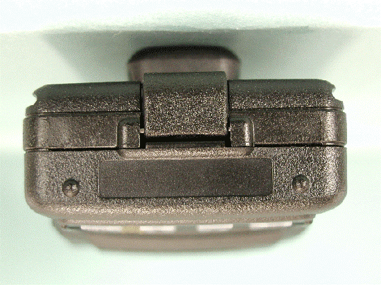
Click to zoom
Application Details
- Equipment Class
- TNF - Licensed Non-Broadcast Transmitter Held to Face
- Date of Grant
- Dec 12, 2001
- Application Purpose
- Original Equipment
- Date of Application
- Sep 25, 2001
- Equipment Note
- Airband Transceiver
- Frequency Range
- 118.00000000 - 136.97500000
- Company
- Yaesu Musen Co., Ltd.
- Country
- Japan
Documents & Files
Document Text
Text extracted from the exhibit documents filed with the FCC. Open a document above to read the original.
Users Manual
Operating Manual HEAVY DUTY AIR BAND TRANSCEIVER VXA-150 CONTENTS Important Notice!................................................1 Introduction.........................................................2 Accessories & Options.......................................3 Controls & Connectors.......................................4 Top Panel................................................................4 LCD Display...........................................................5 Front Panel..............................................................6 Keypad....................................................................7 Left Side..................................................................8 Right Side................................................................9 Before You Begin..............................................10 Precaution..............................................................10 Battery Installation and Removal..........................10 Battery Charging...................................................11 Low Battery Indication..........................................12 Installing the FBA-25 (option) Alkaline Battery Case......................................12 Operation...........................................................13 Preliminary Steps..................................................13 Operation Quick Start............................................13 Accessing the 121.5 MHz Emergency Frequency...........................................15 Tuning Methods....................................................16 Transmission.........................................................17 Reception of Weather Channel Broadcasts............17 Monitor Key..........................................................19 ANL (Automatic Noise Limiter) Feature...............19 LOCK Function.....................................................20 Beep On/Off..........................................................20 Receive Battery Saver Setup.................................21 Memory Operation............................................22 Memory Storage....................................................22 Recalling the Memories.........................................23 Scanning Operation..........................................24 Channel-Skip Scanning.........................................25 Dual Watch Operation.......................................26 Priority Dual Watch Operation.........................27 Split Operation..................................................28 Programming a Transmit Frequency......................28 Operating in the Split Mode..................................28 Field Programming Mode.................................29 Memory Storage into the Book Memory...............29 Menu (“Set”) Mode...........................................30 Menu Listing.........................................................31 Specifications....................................................34 NOTICE There are no user-serviceable points inside this transceiver. All service jobs must be referred to your Authorized Service Center. VXA-150 AVIATOR PROV OPERATING MANUAL VXA-150 AVIATOR PROV OPERATING MANUAL 1 IMPORTANT NOTICE! FCC RF Exposure Compliance Requirements for Occupational Use Only: This Radio has been tested and complies with the Federal Communications Commission (FCC) RF exposure limits for Occupational Use/Controlled exposure environment. In addition, it complies with the following Standards and Guidelines: r FCC 96-326, Guidelines for Evaluating the Environmental Effects of Radio-Frequency Radiation. r FCC OET Bulletin 65 Edition 97-01 (1997) Supplement C, Evaluating Compliance with FCC Guidelines for Human Exposure to Radio Frequency Electromagnetic Fields. r ANSI/IEEE C95.1-1992, IEEE Standard for Safety Levels with Respect to Human Exposure to Radio Frequency Electromagnetic Fields, 3 kHz to 300 GHz. r ANSI/IEEE C95.3-1992, IEEE Recommended Practice for the Measurement of Potentially Hazardous Elec- tromagnetic Fields - RF and Microwave. ¶ This radio is NOT approved for use by the general population in an uncontrolled environment. This radio is restricted to occupational use, work related operations only where the radio operator must have the knowledge to control its RF exposure conditions. ¶ When transmitting, hold the radio in a vertical position with its microphone 1 to 2 inches (2.5 to 5 cm) away from your mouth and keep the antenna at least 1 inch (2.5 cm) away from your head and body. ¶ The radio must be used with a maximum operating duty cycle not exceeding 50%, in typical Push-to- Talk configurations. DO NOT transmit for more than 50% of total radio use time (50% duty cycle). Transmitting more than 50% of the time can cause FCC RF exposure compliance requirements to be exceeded. The radio is transmitting when the red LED on the top of the radio is illuminated. You can cause the radio to transmit by pressing the P-T-T button. ¶ Always use Vertex Standard authorized accessories. VXA-150 AVIATOR PROV OPERATING MANUAL 2 INTRODUCTION The Vertex Standard VXA-150 Aviator ProV is a compact, stylish, solid hand-held transceiver providing communication (transmit and receive) capability on the International Aircraft Communication Band (“COM” band: 118 ~ 136.975 MHz), and it additionally provides receive on the “NAV” band (108 ~ 117.975 MHz). The VXA-150 includes our exclusive two-mode display with upright or inverted viewing when on your belt, NOAA weather band monitoring, 8-character Alpha/Numeric Display, 50 Memory Channels, and 100 “Book Memory” Channels. We recommend that you read this manual in its entirety, so as to understand the many features of the VXA-150 completely. Keep this manual handy, so you may use it for reference. Congratulations! You now have at your fingertips a valuable communications tool-a Vertex Standard two-way radio! Rugged, reliable and easy to use, your Vertex Standard radio will keep you in constant touch with yo…
Text truncated - open the document above for the full version.
Cover Letter(s)
FCC ID: K66VXA-150 MFA p0180006, d0190012 Date of Report: Date of Submission: September 4, 2001 September 26, 2001 Federal Aviation Administration Spectrum Engineering Division ASR-1 800 Independence Ave. S.W. Washington, D.C. 20591 Applicant: Vertex Standard Co., Ltd. FCC ID: K66VXA-150 FCC Rules: 87 Gentlemen: As required under FCC Rule Part 87.147(d) please consider this letter, sent on behalf of the Applicant, as notification of the filing of an application Form 731 for the certification of the referenced equipment. Attached for your records, please find: 1. copy of the FCC Application Form 731 2. copy of the proof of electronic filing to FCC with EA# 3. copy of the covering letter to the Commission 4. copy of the Agent Authorization letter for the writer to act on behalf of the Applicant. 5. Copy of Test Report as sent to the FCC We trust the enclosed complies with your requirements. Should you need any further clarification, kindly contact the writer. Sincerely yours, Morton Flom, P. Eng. MF/cvr enclosure(s) cc: Applicant cc: FCC via Electronic Filing cc: Industry Canada VIA CERTIFIED MAIL
External Photos
Front of EUT with Antenna Back of EUT with Antenna Front of EUT without Antenna Back of EUT without Antenna Right side of EUT Left side of EUT Top of EUT Bottom of EUT Top of Battery Charger Bottom of Battery Charger Top of AC Adapter Bottom of AC Adapter Front of Microphone Back of Microphone Antenna
ID Label/Location Info
VXA-150 VERTEX STANDARD CO., LTD.MADE IN JAPAN FCC ID: K66VXA-150 CANADA: *** *** **** ******* VERTEX STANDARD VXA-150
Internal Photos
Back of EUT without battery pack Battery pack Component side of MAIN-UNIT with LCD Component side of MAIN-UNIT without LCD Solder side of MAIN-UNIT Front of LCD Back of LCD Side-A of VR-UNIT Side-B of VR-UNIT Side-A of SW-UNIT Side-B of SW-UNIT Inside of front panel Inside back of chassis Inside top of battery charger Inside bottom of battery charger Component side of battery charger PCB Solder side of battery charger PCB Inside top of battery charger chassis Inside bottom of battery charger chassis Inside of microphone Inside front of microphone chassis Inside back of microphone chassis Component side of microphone PCB Solder side of microphone PCB
Operational Description
VXA-150 Circuit Description Vertex Standard Co., Ltd. 1 VXA-150 VXA-150 VXA-150 VXA-150 CIRCUIT DESCRIPTION CIRCUIT DESCRIPTIONCIRCUIT DESCRIPTION CIRCUIT DESCRIPTION Receive Signal Path Receive Signal PathReceive Signal Path Receive Signal Path Incoming RF from the antenna jack is passed through a low-pass filter and high- pass filter consisting of coils L1022, L1024, L1026, L1027, L1030 & L1031, capacitors C1237, C1239, C1242, C1245, C1247, C1248, C1249, C1250, C1251, C1252, C1255 & C1257 and antenna switching diodes D1037 and D1039 (both RLS135) to the receiver front end section. Signals within the frequency range of the transceiver is applied to the receiver front end which contains RF amplifier Q1058 (2SC5226) and varactor-tuned band-pass filter consisting of coils L1013, L1017, L1020, L1021, L1028 & L1029, capacitors C1198, C1204, C1205, C1212, C1216, C1217, C1222, C1228, C1232, C1243 & C1253, and diodes D1032, D1034, D1036 & D1042 (all HVC350), then applied to the 1st mixer Q1056 (2SC5226). Buffered output from the VCO is amplified by Q1029 (2SC5226) to provide a pure 1st local signal between 143.4 and 172.4 MHz for injection to the 1st mixer. The 35.4 MHz 1st mixer product then passes through monolithic crystal filter XF1001 (35S15A, 7.5 kHz BW) which strips away all but the desired signal, which is then amplified by mixer post-amp Q1050 (2SC4215Y). The amplified 1st IF signal is applied to the AM/FM IF subsystem IC Q1049 (TK10931V), which contains the 2nd mixer, limiter amplifier, and AM/FM detector. A 2nd local signal is generated by PLL reference/2nd local oscillator Q1045 (2SC4116GR) from the 17.475 MHz crystal X1002. The 17.47 MHz signal is doubled by Q1048 (2SC4116GR) to produce the 450 kHz 2nd IF when mixed with the 1st IF signal within Q1049. The 2nd IF then passes through the ceramic filter CF1001 (ALFYM450F=K) to strip away unwanted mixer products. In the FM mode, a 2nd IF signal from the ceramic filter CF1001 applied to the limiter amplifier section of Q1049, which removes amplitude variations in the 450 kHz IF before detection of the speech by the ceramic discriminator CD 1001 (CDBM450C24T). Detected audio from Q1049 is passed through the de-emphasis, consisting of the resistors R1089, R1095, R1100 & R1149, capacitors C1104, C1105, VXA-150 Circuit Description Vertex Standard Co., Ltd. 2 C1107 & C1151, and Q1028 (NJM2904V). In the AM mode, detected audio from Q1049 is passed through the audio amplifier Q1028 and ANL circuit, then applied to the AF amplifier Q1028. When ANL is on, the ANL MUTE gate Q1027 (UMG2) goes high, the low-pass filter/limiter consisting of capacitor C1124, resistors R1105, R1111, R1112, R1115 & R1119 and diode D1023 (BAS316) is activate, thus reducing the noises when impulse noise received. The processed audio signal from Q1028 passes through the audio mute gate Q1008 (DTC143ZUA) and the volume control to the audio power amplifier Q1009 (TDA72330), providing up to 0.4 Watts to the headphone jack or 8 Ω loudspeaker. A portion of the AF signal from the AM/FM IF subsystem Q1049 converted into DC voltage within the IC, and then passes through the AGC amplifier Q1054 (2SA1602A) and Q1055 (UMW1) to the inversion amplifiers Q1051 and Q1057 (both 2SC5226). These amplifier reduce the amplifier gain of the IF amplifier Q1050 and the RF amplifier Q1058 while receiving a strong signal. Squelch Control Squelch ControlSquelch Control Squelch Control When a signal is received, a DC squelch control voltage appears at pin 15 of AM/FM IF subsystem Q1049 according to the receiving signal strength. This DC is applied to pin 2 of microprocessor Q1014. The DC squelch control voltage is compared with the SQL threshold level by the microprocessor Q1014. If the DC squelch control voltage is higher, pin 49 of Q1014 goes low. This signal disable the AF MUTE gate Q1008 (DTC143ZUA), thus activating the AF audio. Also, the microprocessor stops scanning, if active, and allows audio to pass through the AF MUTE gate Q1008. Transmit Signal Path Transmit Signal PathTransmit Signal Path Transmit Signal Path Speech input from the microphone is passed through the microphone sensitivity potentiometer VR1001 and microphone amplifier Q1005-3 (NJM2902V), then applied VXA-150 Circuit Description Vertex Standard Co., Ltd. 3 to the ALC amplifier Q1007 (AN6123MS). The amplified speech signal is passed through the high-pass filter Q1005-1 (NJM2902V) and low-pass filter Q1005-2 (NJM2904V), then applied to the power amplifier Q1052 (2SK2974) which AM modulate the Tx frequency with speech signal. When using the optional headset, the SIDETONE signal from Q1011 (UMG2) becomes “HIGH”, turning Q1012 (2SC4116GR) on, therefore a portion of the speech signal applied to the AF power amplifier Q1009 as a monitor signal. The carrier signal from the VCO Q1023 (2SC5226) passes through the buffer amplifier Q1029 (2SC5226) and TX/RX switch D1031 (MC2848), then amplified by Q1043 (2SC3356) and Q1047 (2SK2973), then applied to the power amplifier Q1052 which increases the signal level up to 5 watts output power. The transmit signal then passes through the antenna switch D1037 (RLS135), and is low-pass filtered to suppress away harmonic spurious radiation before delivery to the antenna. Automatic Transmit Power Control Automatic Transmit Power ControlAutomatic Transmit Power Control Automatic Transmit Power Control RF power output from the final amplifier is sampled by C1241/C1244 and is rectified by D1040 (HSM88WA). The resulting DC voltage passes through the Automatic Power Controller Q1005 (NJM2902V) to the APC attenuator D1015 (RN739F) and final amplifier Q1052, so as to control the power output. Transmit Inhibit Transmit InhibitTransmit Inhibit Transmit Inhibit When the transmit PLL is unlocked, pin 7 of PLL chip Q1032 (MB15A01PFV1) goes to a logic low. The resulting DC “unlock” control voltage is switches off TX inhibit switches Q1035 (2SA1602A), Q1037 (UMW1) and Q1041 (DTA143EU) to disable the supply volt…
Text truncated - open the document above for the full version.
Parts List/Tune Up Info
VXA-150 Alignment Vertex Standard Co., Ltd. 1 Introduction IntroductionIntroduction Introduction The VXA-150 is carefully aligned at the factory for the specified performance across the Aircraft and Weather bands. Realignment should therefore not be necessary except in the event of a component failure. The following procedures cover the adjustments that are not normally required once the transceiver has left the factory. However, if damage occurs and some parts subsequently are replaced, realignment may be required. If a sudden problem occurs during normal operation, it is likely due to component failure; realignment should not be done until after the faulty component has been replaced. We recommend that servicing be performed only by authorized Vertex Standard service technicians who are experienced with the circuitry and fully equipped for repair and alignment. If a fault is suspected, contact the dealer from whom the transceiver was purchased for instructions regarding repair. Under no circumstances should any alignment be attempted unless the normal function and operation of the transceiver are clearly understood, the cause of the malfunction has been clearly pinpointed and any faulty components replaced, and realignment determined to be absolutely necessary. Problems caused by unauthorized attempts at realignment are not covered by the warranty policy Vertex Standard reserves the right to change circuits and alignment procedures, in the interest of improved performance, without notifying owners. The following test equipment (and familiarity with its use) is necessary for complete realignment. While most steps do not require all of the equipment listed, the interactions of some adjustments may require that more complex adjustments be performed afterwards. Do not attempt to perform only a signal step unless it is clearly isolated electrically from all other steps. Have all test equipment ready before beginning, and follow all of the steps in a section in the order presented. Correction of problems caused by misalignment resulting from use of improper test equipment is not covered under the warranty policy. Note: Signal levels in dB refereed to in this procedure are based on 0 dBμ = 0.5 μV (closed circuit). VXA-150 Alignment Vertex Standard Co., Ltd. 2 Required Test Equipment Required Test EquipmentRequired Test Equipment Required Test Equipment R Radio Tester with calibrated output level at 200 MHz R In-line Wattmeter with 5% accuracy at 200 MHz R 50-Ω, 10-W RF Dummy Load R Regulated DC Power Supply adjustable from 3 to 15 VDC, 2A R Frequency Counter: ±0.2 ppm accuracy at 200 MHz R AF Signal Generator R AC Voltmeter R DC Voltmeter: high impedance R VHF Sampling Coupler Alignment Preparation & Precautions Alignment Preparation & PrecautionsAlignment Preparation & Precautions Alignment Preparation & Precautions A 50-Ω RF load and in-line wattmeter must be connected to the main antenna jack in all procedures that call for transmission, except where specified otherwise. Correct alignment is not possible with an antenna. After completing one step, read the next step to see if the same test equipment is required. If not, remove the test equipment (except dummy load and wattmeter, if connected) before proceeding. Correct alignment requires that the ambient temperature be the same as that of the transceiver and test equipment, and that this temperature be held constant between 20~30 °C (68-86 °F). When the transceiver is brought into the shop from hot or cold air, it should be allowed some time to come to room temperature before alignment. Whenever possible, alignments should be made with oscillator shields and circuit boards firmly affixed in place. Also, the test equipment must be thoroughly warmed up before beginning. Set up the test equipment as shown below for transceiver alignment, apply 7.2 VDC power to the transceiver. Refer to the drawings for Alignment Points. PLL Reference Frequency PLL Reference FrequencyPLL Reference Frequency PLL Reference Frequency R Connect the wattmeter, dummy load and frequency counter connected to the antenna jack, and tune the transceiver to 120.000 MHz. R Transmit, and adjust TC1001 on the RF Unit, if necessary, so the counter frequency is 120.000 MHz (±100 Hz). VXA-150 Alignment Vertex Standard Co., Ltd. 3 TX Power Adjustment TX Power AdjustmentTX Power Adjustment TX Power Adjustment R Connect the wattmeter and dummy load to the antenna jack, and tune the transceiver to 128.000 MHz. R Transmit, and adjust VR1003 to obtain 1.5 W RF (carrier) power indicated on the wattmeter (without audio modulation input). TX TXTX TX Modulation Adjustment Modulation Adjustment Modulation Adjustment Modulation Adjustment R Connect the Radio Tester to the antenna jack, then adjust the AF generator output level for injection of 200 mV rms @ 1 kHz to the MIC jack. Leave the transceiver tuned to 127.500 MHz. R Transmit, and adjust VR1002 to obtain 85 % modulation (±3 %) as indicated on the Radio Tester. R Reduce the AF generator output level to 20 mV rms, then adjust VR1001 to obtain 30 % modulation (±3 %) on the Radio Tester. Internal System Alignment Routine Internal System Alignment RoutineInternal System Alignment Routine Internal System Alignment Routine This feature uses a programmed routine in the transceiver which replaces many previously-complex discrete component settings and adjustments with digitally- controlled settings via the CHANNEL selector knob. Transceiver adjustments include: Squelch Hysteresis Adjustment Squelch Threshold Adjustment Squelch “Tight” Adjustment To begin, set the transceiver to 127.500 MHz, and turn the transceiver off. Then, press and holding the LAMP switch, PTT switch and the CHANNEL selector knob while turning the transceiver on. Squelch Hysteresis Adjustment (HSSQ) Press the CHANNEL selector knob, then select the squelch hysteresis level using the CHANNEL selector knob. Next, press the CHANNEL selector knob. Rotate the CHA…
Text truncated - open the document above for the full version.
Parts List/Tune Up Info
Page 1/2 Location Parts TypeNomenciatureApplication Q 1001Transistor2SB1132Charge REG Q 1002TransistorUMZ2N PTT switch Q 1003Transistor2SB1132Mic amp. REG Q 1004Transistor2SC4116GRMIC Mute SW Q 1005ICNJM2902VMic amplifier Q 1006TransistorRT1N241MMic amp. REG SW Q 1007ICAN6123MSALC amp. Q 1008TransistorDTC143ZUA AF Mute SW Q 1009ICTDA7233DAF Power amplifier Q 1010Transistor2SB1132 AF AMP.control switch Q 1011TransistorUMG2NSidetone SW Q 1012Transistor2SC4116GR AF AMP.control switch Q 1013Transistor2SC4116GR Clock shift switch Q 1014ICM38257E8-GPMicroprocessor Q 1015ICAK93C85AM EEPROM Q 1016Transistor2SC4116GR Ripple filter Q 1017TransistorUMG2NRX switch Q 1018TransistorDTA143EU RX SAVE switch Q 1019TransistorDTC124TUReset control Q 1020TransistorDTA143EU RX switch Q 1021TransistorRT1N241MVCO Shift switch Q 1022TransistorDTA143EURX SAVE switch Q 1023Transistor2SC5226VCO Q 1024ICS-80745SNVoltage detect Q 1025TransistorRT1P441URX SAVE switch Q 1026TransistorRT1N241MMode SW Q 1027TransistorUMG2N ANL SW Q 1028ICNJM2904VAF amplifier Q 1029Transistor2SC5226Buffer amplifier Q 1030ICS-81235SGUP3.5V regulator Q 1031TransistorDTC143ZUALED driver Q 1032ICMB15A01PFV1PLL subsystem Q 1033Transistor2SB11325V regulator Q 1034TransistorUMW15V regulator Q 1035Transistor2SA1602ATX unlock switch Q 1036Transistor2SC5226Buffer amplifier Q 1037TransistorUMW1TX unlock switch Q 1039TransistorUMW15V regulator Q 1040Transistor2SB1132 5V regulator Q 1041TransistorDTA143EU TX unlock switch Q 1042FET2SK880GRVCV Buffer Q 1043Transistor2SC3356Driver amplifier Q 1044Transistor2SB1132Tx switch Q 1045Transistor2SC4116GRReference Oscillator Q 1046TransistorUMW1Tx switch Q 1047FET2SK2973Exciter amplifier Q 1048Transistor2SC4116GRRF amplifier Q 1049ICTK10931VIF subsystem Q 1050Transistor2SC4215Y IF amplifier Q 1051Transistor2SC5226AGC Control VXA-150 Component Applications Vertex Standard Co., Ltd. Page 2/2 Location Parts TypeNomenciatureApplication VXA-150 Component Applications Q 1052FET2SK2974Power amplifier Q 1053TransistorRT1N241MMode SW Q 1054Transistor2SA1602AAGC amplifier Q 1055TransistorUMW1AGC amplifier Q 1056Transistor2SC52261st mixer Q 1057Transistor2SC5226AGC Control Q 1058Transistor2SC5226RF amplifier Q 1059TransistorRT1N241MAF AMP.control switch D 1001Zener Diode02CZ2.0XVoltage limitter D 1002DiodeBAS316Reverse protector D 1003DiodeBAS316Reverse protector D 1004DiodeSB40W03TRegulator switch D 1005DiodeMC2848Reverse voltage protector D 1006DiodeBAS316Reverse voltage protector D 1007DiodeMC2850Voltage protector D 1008DiodeMC2850Voltage control D 1009DiodeBAS316Reverse protector D 1012Zener DiodeRD6.8UMB2Voltage control D 1014DiodeBAS316Reverse protector D 1015DiodeRN739FModulation attenuater D 1016DiodeHVC350BVCO D 1017DiodeBAS316Ripple filter D 1018DiodeMC2850Reverse protector D 1019DiodeMC2850Reset control D 1020DiodeHSU277TRFVCO Shift switch D 1021DiodeBAS316Reverse protector D 1022DiodeBAS316Voltage protector D 1023DiodeBAS316ANL D 1024Zener DiodeHZU4ALLVoltage protector D 1025LEDAA1101FIllumination D 1026LEDAA1111CIllumination D 1027LEDAA1111CIllumination D 1029LEDAA1111CIllumination D 1030LEDAA1111CIllumination D 1031DiodeMC2848TX/RX switch D 1032Varactor DiodeHVC350BBPF tune D 1033DiodeBAS316AGC D 1034Varactor DiodeHVC350BBPF tune D 1036Varactor DiodeHVC350BBPF tune D 1037DiodeRLS135Antenna switch D 1039DiodeRLS135Antenna switch D 1040DiodeHSM88WAPower detect D 1041DiodeRN739FRF level limitter D 1042Varactor DiodeHVC350BBPF tune D 1043DiodeBAS316APC Vertex Standard Co., Ltd.
RF Exposure Info
CELLTECH RESEARCH INC. Test Report S/N: 091801-167K66 1955 Moss Court, Kelowna Date(s) of Tests: Sept. 19, 2001 B.C. Canada V1Y 9L3 FCC SAR Evaluation _________________________________________________________________________________________________________ © 2001 Celltech Research Inc. CERTIFICATE OF COMPLIANCE SAR EVALUATION This wireless portable device has been shown to be compliant for localized Specific Absorption Rate (SAR) for controlled environment/occupational exposure limits specified in ANSI/IEEE Std. C95.1-1992 and had been tested in accordance with the measurement procedures specified in ANSI/IEEE Std. C95.3-1999. I attest to the accuracy of data. All measurements were performed by me or were made under my supervision and are correct to the best of my knowledge and belief. I assume full responsibility for the completeness of these measurements and vouch for the qualifications of all persons taking them. Celltech Research Inc. certifies that no party to this application has been denied FCC benefits pursuant to Section 5301 of the Anti-Drug Abuse Act of 1988, 21 U.S.C. 853(a). Shawn McMillen General Manager Celltech Research Inc. Test Lab: CELLTECH RESEARCH INC. Testing and Engineering Lab 1955 Moss Court Kelowna, B.C. Canada V1Y 9L3 Phone: 250 - 860-3130 Fax: 250 - 860-3110 Toll Free: 1-877-545-6287 e-mail: [email protected] web site: www.celltechlabs.com Applicant Information: VERTEX STANDARD CO., LTD. 4-8-8, Nakameguro, Meguro-Ku Tokyo 153-8644, Japan FCC Rule Part(s): 2.1093; ET Docket 96-326 FCC ID: K66VXA-150 Model(s): VXA-150 EUT Type: Portable PTT Air Band Radio Transceiver Modulation: AM Tx Frequency Range: 118.000 - 136.975 MHz Conducted Power Tested: 1.55 W (118.000 MHz) 1.53 W (127.500 MHz) 1.43 W (136.975 MHz) IC Rule Part(s): RSS-102 Issue 1 CELLTECH RESEARCH INC. Test Report S/N: 091801-167K66 1955 Moss Court, Kelowna Date(s) of Tests: Sept. 19, 2001 B.C. Canada V1Y 9L3 FCC SAR Evaluation _________________________________________________________________________________________________________ © 2001 Celltech Research Inc. TABLE OF CONTENTS 1.0 INTRODUCTION.................................................................. 1 2.0 DESCRIPTION OF EUT.......................................................... 1 3.0 SAR MEASUREMENT SYSTEM ............................................. 2 4.0 SAR MEASUREMENT SUMMARY.......................................... 3-4 5.0 DETAILS OF SAR EVALUATION............................................ 5 6.0 EVALUATION PROCEDURES................................................. 5 7.0 SAR LIMITS........................................................................ 6 8.0 SYSTEM VALIDATION.......................................................... 6 9.0 SIMULATED EQUIVALENT TISSUES...................................... 7 10.0 TISSUE PARAMETERS......................................................... 7 11.0 SYSTEM SPECIFICATIONS.................................................... 8 12.0 PROBE SPECIFICATION....................................................... 9 13.0 SAM PHANTOM.................................................................... 9 14.0 DEVICE HOLDER................................................................. 9 15.0 TEST EQUIPMENT LIST........................................................ 10 16.0 MEASUREMENT UNCERTAINTIES........................................ 11 17.0 REFERENCES...................................................................... 12 APPENDIX A - SAR MEASUREMENT DATA........................................ 13 APPENDIX B - DIPOLE VALIDATION................................................ 14 APPENDIX C - PROBE CALIBRATION............................................... 15 APPENDIX D - SAR TEST SETUP PHOTOGRAPHS............................... 16 CELLTECH RESEARCH INC. Test Report S/N: 091801-167K66 1955 Moss Court, Kelowna Date(s) of Tests: Sept. 19, 2001 B.C. Canada V1Y 9L3 FCC SAR Evaluation _________________________________________________________________________________________________________ © 2001 Celltech Research Inc. VERTEX STANDARD FCC ID: K66VXA-150 1 AM PTT Air Band Radio Transceiver (118-137MHz) 1.0 INTRODUCTION This measurement report shows compliance of the VERTEX STANDARD CO., LTD. Model: VXA-150 Portable Air Band PTT AM Radio Transceiver FCC ID: K66VXA-150 with the regulations and procedures specified in FCC Part 2.1093, ET Docket 96-326 Rules (controlled exposure), and RSS-102 Issue 1 of Industry Canada for mobile and portable devices. The test procedures, as described in American National Standards Institute C95.1-1992 (1), FCC OET Bulletin 65, Supplement C (Edition 01-01) were employed. A description of the product and operating configuration, detailed summary of the test results, methodology and procedures used in the evaluation, equipment used, and the various provisions of the rules are included within this test report. 2.0 DESCRIPTION of Equipment Under Test (EUT) Front of EUT Right Side of EUT Left Side of EUT Back of EUT EUT with Spkr/Mic Rule Part(s) FCC 2.1093 ET Docket 96.326 IC RSS-102 Issue 1 Modulation AM EUT Type Portable Air Band PTT Radio Transceiver Tx Frequency Range (MHz) 118.000 - 136.975 FCC ID K66VXA-150 Conducted Power Tested 1.55 W (118.000 MHz) 1.53 W (127.500 MHz) 1.43 W (136.975 MHz) Model No.(s) VXA-150 Antenna Type(s) Helical Whip Serial No. Pre-production Power Supply Ni-Cd Battery (DC 7.2V 700mAh) CELLTECH RESEARCH INC. Test Report S/N: 091801-167K66 1955 Moss Court, Kelowna Date(s) of Tests: Sept. 19, 2001 B.C. Canada V1Y 9L3 FCC SAR Evaluation _________________________________________________________________________________________________________ © 2001 Celltech Research Inc. VERTEX STANDARD FCC ID: K66VXA-150 2 AM PTT Air Band Radio Transceiver (118-137MHz) 3.0 SAR MEASUREMENT SYSTEM Celltech Research SAR measurement facility utilizes the Dosimetric Assessment System (DASY™) manufactured by Schmid & Partner Engineering AG (SPEAG™) of Zurich, Switzerl…
Text truncated - open the document above for the full version.
RF Exposure Info
Celltech Research Inc. 1955 Moss Court, Kelowna, B.C. Canada V1Y 9L3 Tel. 250-860-3130 •• Fax. 250-860-3110 •• e-mail: [email protected] www.celltechlabs.com November 19, 2001 Federal Communications Commission Equipment Approval Services 7435 Oakland Mills Road Columbia, MD 21046 Attn: A…
Text truncated - open the document above for the full version.
Contact Information
Applicant
Masatoshi Muraishi(Engineering Division)
Technical Contact
M. Flom Associates, IncMorton Flom
480 926 3100
3356 N. San Marcos Pl., Suite 107 · Chandler, Arizona · United States
Non-Technical Contact
M. Flom Associates, Inc.Morton Flom
[email protected]480 926 3100
Test Firm
M. Flom Associates, Inc.Morton Flom
Technical Specifications
| # | Rule Parts | Frequency Range | Power Output | Emission | Tolerance |
|---|---|---|---|---|---|
| 1 | 87 | 118 MHz - 136.975 MHz | 1.55 W | 6K00A3E | 10.0000000000 % |
Other Applications from Yaesu Musen Co., Ltd.
K660E180X10
Dec 01, 2025BLUETOOTH MICROPHONE
Equipment Class
DTS - Digital Transmission System
K6630673Y3D
Aug 01, 2024VHF FM Marine Transceiver
Equipment Class
CXX - Communications Rcvr for use w/ licensed Tx and CBs
K6630653Y3D
Aug 01, 2024VHF FM Marine Transceiver
Equipment Class
CXX - Communications Rcvr for use w/ licensed Tx and CBs
K6630683X30
Jan 10, 2023VHF FM Marine Transceiver
Equipment Class
TNF - Licensed Non-Broadcast Transmitter Held to Face
K6650033X30
Nov 18, 2020Airband Radio Transceiver
Equipment Class
TNF - Licensed Non-Broadcast Transmitter Held to Face