K66VXR-7000UUHF-FM Desktop Repeater
Yaesu Musen Co., Ltd.
Click to zoom
Application Details
- Equipment Class
- TNB - Licensed Non-Broadcast Station Transmitter
- Date of Grant
- Feb 24, 2000
- Application Purpose
- Original Equipment
- Date of Application
- Dec 28, 1999
- Equipment Note
- UHF-FM Desktop Repeater
- Frequency Range
- 450.00000000 - 485.00000000
- Company
- Yaesu Musen Co., Ltd.
- Country
- Japan
Documents & Files
Document Text
Text extracted from the exhibit documents filed with the FCC. Open a document above to read the original.
Users Manual
VXR-7000U Operating Manual YAESU MUSEN CO., LTD. 4-8-8 Nakameguro, Meguro-Ku, Tokyo 153-8644, Japan YAESU U.S.A. 17210 Edwards Rd., Cerritos, CA 90703, U.S.A. YAESU EUROPE B.V. P.O. Box 75525 1118 ZN, Schiphol, The Netherlands YAESU UK LTD. Unit 12, Sun Valley Business Park, Winnall Close Winchester, Hampshire, SO23 0LB, U.K. YAESU GERMANY GmbH Am Kronberger Hang 2, D-65824 Schwalbach, Germany YAESU HK LTD. 11th Floor Tsim Sha Tsui Centre, 66 Mody Rd., Tsim Sha Tsui East, Kowloon, Hong Kong Contents Introduction Controls & Connectors Front Panel Rear Panel ACC Connector Port LINE Interface Port Installation Antenna Considerations VXR-7000U FM REPEATER OPERATING MANUAL 1 AC Power Supply Voltage Selection DC Power Supply Backup Equipment Location Changing Switching Regulator unit AC Mains Jumper Wiring CE-27 Programming Software Instruction Channel Data Items Duplexer Installation Specifications Accessories Introduction The VXR-7000 is commercial quality 50-watt FM repeater designed to provide reliable, continuous- duty two-way communications over a wide range of environmental conditions. Designed to be a stylish base station, with high-grade components utilized throughout, the VXR-7000 utilizes the latest computer-aided design and manufacturing processes to ensure a high level of reliability for users. Important channel frequency data is stored in EEPROM, and is easily programmable by a Servicing Technician or Dealer using an IBM compatible personal computer and the VPL-1 Programming Cable and CE-27 Software. Please take a few minutes to read this manual carefully. The information presented here will allow you to derive maximum performance from your VXR-7000. After reading it, keep this manual handy for quick reference, in case questions arise later on. Important Note: Internal service work, programming, and accessory installations should only be performed by your authorized Vertex Dealer. Dangerous conditions and/or possibly illegal operation may result from improper setup, programming, or internal modifications. Controls & Connectors Front Panel 1: POWER Switch This is the main power switch for the repeater. VXR-7000U FM REPEATER OPERATING MANUAL 2 2: LED Indicators AC: This LED glows green during AC operation. DC: This LED glows yellow during DC operation. 3: MIC Jack This 8-pin modular jack accepts the microphone input, and provides a standby control line to activate the transmitter when using the “BASE” mode of operation. This jack also provides a “Hook” control line, as well as a “Clone Data” line. 4: BASE/REPEATER Switch This switch toggles the operating mode between the “REPEATER” mode and the “BASE” transceiver mode. When the “REPEATER” mode is selected, the LED above it glows green. While in the “BASE” mode (the green LED is off), you can speak into the microphone to use it as a transceiver. For normal repeater operation, set this switch to the “REPEATER” mode. 5: LOCAL/REMOTE Switch This switch toggles the control mode between the “REMOTE” mode and “LOCAL” mode. When the “LOCAL” mode is selected, the LED above it is off, and the repeater operates according to the control data programmed into the repeater. While in the “REMOTE” mode, the LED glows green, and the repeater operates according to the control instructions received from an external device (connected to the ACC jack on the rear panel). 6: MONITOR Switch This switch selects the “Squelch” (receiver mute) mode. When the green LED above it is off, “Tone” or “Coded” squelch is active. When you press this switch momentarily, the green LED will glow steadily; in this condition, only “noise squelch” is active, and any signal present on the channel will be heard. If you press and hold this switch for more than 2 second, the green LED will blink and the squelch will open; in this condition, background noise will be heard if no signal is present. 7: ACCESSORY Switch This switch can be set up for special applications, such as High/Low power selection, as determined by your Vertex Standard dealer. The LED above it glows green when this function is activated. For further details, contact your Vertex Standard dealer. 8: VOL Knob This control knob adjusts the receiver volume level from the front panel speaker. If desired, this control knob may be set fully counterclockwise when repeater monitoring is not needed. 9: SQL Knob This control knob selects the noise squelch threshold level. Set it to a position just above the point where the BUSY lamp goes out when no signal is present. 10: Channel Selector Buttons (^ and v) Press one of these buttons to select the operating channel. 11: Channel Indicator This seven-segment LED indicates the operating channel number. 12: ANI Display The ANI LCD (Liquid Crystal Display) indicates the pre-programmed ANI message according to the ANI code received. 13: TX/BUSY Indicator The BUSY indicator glows green when the channel is busy, and the TX indicator glows red when the repeater is transmitting. 14: ANI RESET Button (1) ANI Press this button to clear the message on the ANI display, and turn off the LCD backlight. (2) ENI Press this button to turn off the Alert tone. VXR-7000U FM REPEATER OPERATING MANUAL 3 Press this button again to clear the message on the ANI display, and turn off the LCD backlight. Rear Panel 1: EXT SP Jack This 3.5-mm, 2-pin jack provides variable audio output for an external speaker. The audio output impedance at this jack is 4ohms ~ 16ohms and level varies according to the setting of the front panel’s VOL control. 2: TX Antenna Jack This N-type coaxial jack provides the transmitting output signal for connection to the transmitting antenna or TX jack on the duplexer, if used. The output impedance requirement is 50 W. 3: RX Antenna Jack This N-type coaxial jack accepts the receiver input signal from the receiving antenna or RX jack on the duplexer, if used. The input impedance requirement is 50 W. 4: ACC Jack This DB-25 connector provides a data interface between the microprocess…
Text truncated - open the document above for the full version.
Attestation Statements
December 15th, 1999 Federal Communications Commission Authorization and Evaluation Division, 7435 Oakland Mills Road Columbia, MD 21045 USA Re: VXR-7000U (FCC ID: K66VXR-7000U) Gentlemen: The equipment meets the requirements of the FCC Rules, Part 90.203(e) and (g), as applicable. Programming of this product’s transmit frequencies can be performed ONLY by the manufacturer or by service or maintenance personal. The operator cannot be program transmit frequencies using the equipment’s external operation controls. Sincerely, YAESU MUSEN CO., LTD. Mr. Hiroyuki Edo General Manager of Export Department
Block Diagram
YAESU MUSEN Co., LTD K66VXR-7000U YAESU MUSEN Co., LTD K66VXR-7000U YAESU MUSEN Co., LTD K66VXR-7000U
External Photos
YAESU MUSEN Co., LTD K66VXR-7000U YAESU MUSEN Co., LTD K66VXR-7000U YAESU MUSEN Co., LTD K66VXR-7000U YAESU MUSEN Co., LTD K66VXR-7000U
ID Label/Location Info
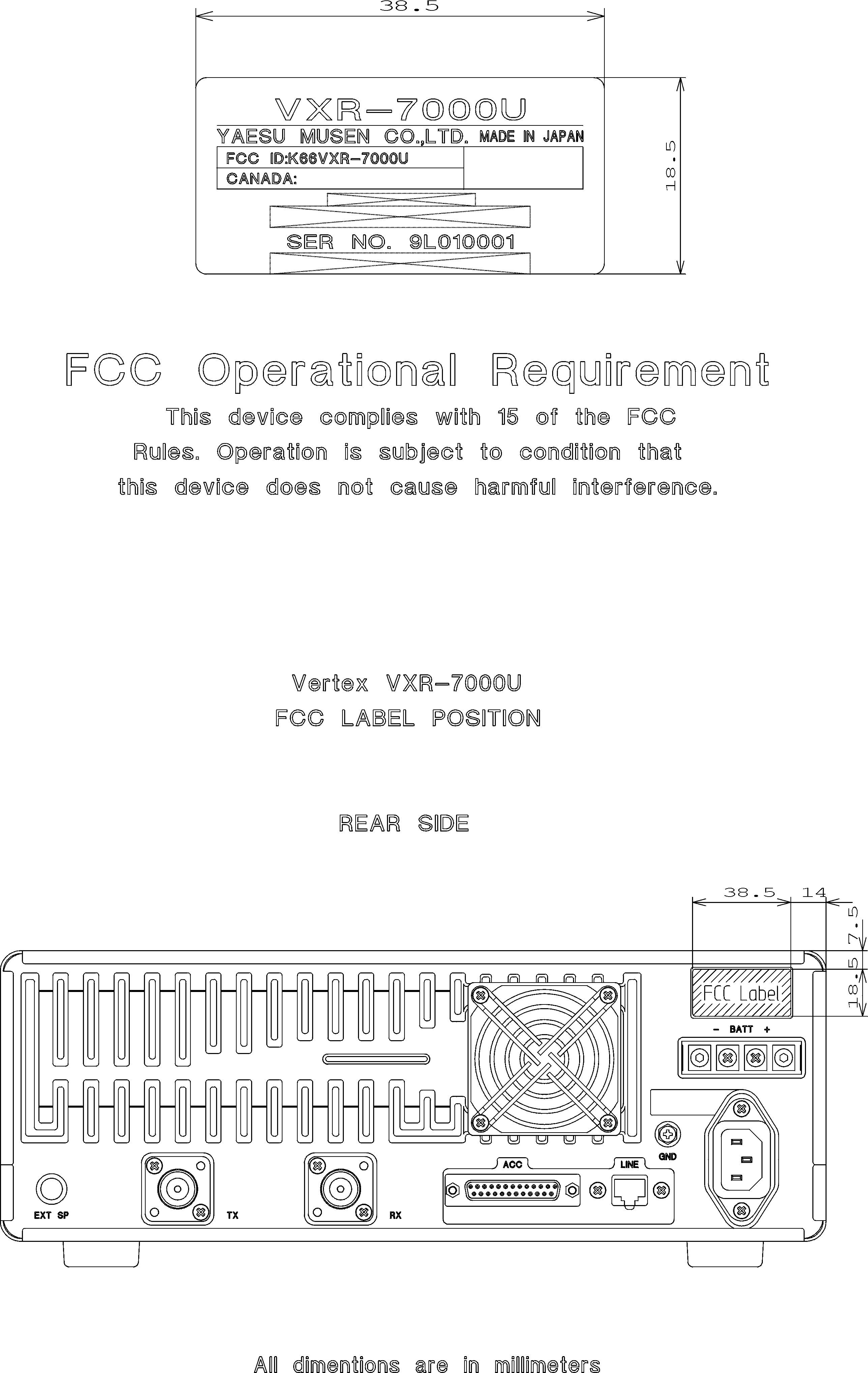
December 15th, 1999 Federal Communications Commission Authorization and Evaluation Division, 7435 Oakland Mills Road Columbia, MD 21045 USA Re: VXR-7000U (FCC ID: K66VXR-7000U) Gentlemen: A. Part 15·19 & 15·21 Compliance Statement Drawing: B. Part 15·19 & 15·21 ComplianceStatement Drawing Location: IN OPERATION MANUAL (location on inside back cover) Sincerely, YAESU MUSEN CO., LTD. Mr. Hiroyuki Edo General Manager of Export Department 20mm This device complies with part 15 of the FCC rules. Operation is subject to the condition that this device dose not cause harmful interference. 97mm
Internal Photos
YAESU MUSEN Co., LTD K66VXR-7000U YAESU MUSEN Co., LTD K66VXR-7000U YAESU MUSEN Co., LTD K66VXR-7000U YAESU MUSEN Co., LTD K66VXR-7000U YAESU MUSEN Co., LTD K66VXR-7000U YAESU MUSEN Co., LTD K66VXR-7000U YAESU MUSEN Co., LTD K66VXR-7000U YAESU MUSEN Co., LTD K66VXR-7000U YAESU MUSEN Co., LTD K66VXR-7000U YAESU MUSEN Co., LTD K66VXR-7000U YAESU MUSEN Co., LTD K66VXR-7000U YAESU MUSEN Co., LTD K66VXR-7000U
Parts List/Tune Up Info
VXR-7000U Component Application 1/6 VXR-7000U Component Application [PA-UNIT] LocationTypeNomenclatureApplication D 1501DiodeRN739FRF SWITCH D 1502DiodeMA143BIAS D 1503Diode1SS319DETECTOR D 1504Diode1SS319DETECTOR Q 1501Transistor2SC3357-T2RF AMP Q 1502RF ModulePF0342RF DRIVE AMP Q 1503Transistor2SB1122SAVR Q 1504Transistor2SC4116GRAVR Q 1505Transistor2SB1122SDC SWITCH Q 1506TransistorUN5213DC SWITCH Q 1507Transistor2SC3102RF POWER AMP Q 1508ICNJM78L09UAREGULATOR Q 1509ICTA75S01FAPC AMP [TX-UNIT] LocationTypeNomenclatureApplication D 2001DiodeRD6.8UMB2AVR D 2002DiodeHVU350TRFOSC D 2003DiodeHVU350TRFOSC D 2004DiodeHVU350TRFMODULATION D 2005DiodeHVU350TRFOSC D 2006DiodeHVU350TRFOSC D 2007DiodeHVU350TRFCOMPENSATION D 2008DiodeHVU350TRFMODULATION D 2009DiodeRN739FRF SWITCH D 2010DiodeRN739FRF SWITCH D 2011DiodeMA143COMPENSATION D 2012DiodeMA143COMPENSATION Q 2001ICMB15A02PFV1PLL Q 2002Transistor2SC4116GROSC Q 2003Transistor2SA1586YDETECTOR Q 2004TransistorUN5215SWITCH Q 2005Transistor2SK508-T2BOSC Q 2006Transistor2SC4116GRCOMPENSATION Q 2007Transistor2SA1586YCOMPENSATION Q 2008Transistor2SC5226BUFFER Q 2009Transistor2SC4116GRREGULATOR Q 2010Transistor2SC3357RF AMP Q 2011TransistorXN1213SWITCH Q 2012ICNJM78L05UAREGULATOR Q 2013Transistor2SA1179M6SWITCH Q 2014TransistorUN5213SWITCH Q 2015TransistorUN5213SWITCH Q 2016Transistor2SA1179M6SWITCH VXR-7000U Component Application 2/6 Q 2019TransistorXN1213OSC SWITCH Q 2020ICNJM2904MCOMPARATOR Q 2021Transistor2SD1664SWITCH Q 2022Transistor2SD1664SWITCH [RX-UNIT] LocationTypeNomenclatureApplication D 3001DiodeMA143PROTECTION D 3002DiodeRD6.8UMB2AVR D 3003DiodeRN739FRF SWITCH D 3004DiodeHVU350TRFRF TUNING D 3005DiodeHVU350TRFOSC D 3006DiodeHVU350TRFOSC D 3007DiodeHVU350TRFRF TUNING D 3008DiodeHVU350TRFOSC D 3009DiodeHVU350TRFOSC D 3010DiodeHVU350TRFCOMPENSATION D 3011ICGN2011-QMIXER D 3012DiodeMA142WKSWITCH D 3013DiodeMA142WKSWITCH D 3014DiodeRD5.6NB2AVR D 3015DiodeMA142WKNOISE DET D 3016DiodeMA142WKCOMPENSATION D 3017DiodeMA143COMPENSATION D 3018DiodeMA143COMPENSATION D 3019DiodeHVU350TRFRF TUNING D 3020DiodeHVU350TRFRF TUNING Q 3001ICMB15A02PFV1PLL Q 3002Transistor2SC4116GROSC Q 3003Transistor2SA1586YDETECTOR Q 3004TransistorUN5215SWITCH Q 3005Transistor2SC3357-T2RF AMP Q 3006Transistor2SC4116GRCOMPENSATION Q 3007Transistor2SA1586YCOMPENSATION Q 3008Transistor2SK508-T2BOSC Q 3009Transistor2SC5226-4/5BUFFER Q 3010Transistor2SC4116GRREGULATOR Q 3011Transistor2SC3357RF AMP Q 3012ICTA31136FNIF DEM. Q 3013Transistor2SC2812L6-TAAVR Q 3014Transistor2SC5226IF AMP Q 3015Transistor2SC4116GRNOISE AMP Q 3016TransistorXN1213SWITCH Q 3017Transistor2SC5226IF AMP Q 3018Transistor2SB1122S-TDSWITCH Q 3020TransistorXN1213SWITCH Q 3021ICNJM78L05UAAVR Q 3022TransistorXN1213SWITCH VXR-7000U Component Application 3/6 [CNTL-UNIT] LocationTypeNomenclatureApplication D 4001DiodeDA204KStatic Voltage Protection D 4002DiodeDA204KStatic Voltage Protection D 4003DiodeDA204KStatic Voltage Protection D 4004DiodeDA204KStatic Voltage Protection D 4005DiodeDA204KStatic Voltage Protection D 4006DiodeDA204KStatic Voltage Protection D 4007DiodeD1F20Reverse Voltage Protection D 4008Zener DiodeHZM7CLevel Shift D 4009DiodeDA204KStatic Voltage Protection D 4010Diode1SS355Discharge D 4011Diode1SS355Switch D 4012DiodeDA204KStatic Voltage Protection D 4013Diode1SS355Switch D 4014Diode1SS355Switch D 4015DiodeMA729Switch D 4016DiodeDA204KStatic Voltage Protection D 4017DiodeDA204KStatic Voltage Protection D 4018DiodeDA204KStatic Voltage Protection D 4019DiodeDA204KStatic Voltage Protection D 4020DiodeDA204KStatic Voltage Protection D 4021DiodeDA204KLimiter D 4022DiodeDA204KStatic Voltage Protection D 4023DiodeDA204KStatic Voltage Protection D 4024DiodeDA204KStatic Voltage Protection D 4025Diode1SS184Switch D 4026Diode1SS184Switch D 4027Surge absorberERZ-V07D121Surge absorber D 4028Surge absorberERZ-V07D121Surge absorber D 4029Surge absorberERZ-V07D121Surge absorber D 4030Surge absorberERZ-V07D121Surge absorber D 4031Surge absorberERZ-V07D121Surge absorber D 4032Surge absorberERZ-V07D121Surge absorber D 4033Surge absorberERZ-V07D121Surge absorber D 4034Surge absorberERZ-V07D121Surge absorber D 4036DiodeMA143Compensation D 4037DiodeMA143Compensation Q 4001ICUPC2409AHF9V Regulator Q 4002ICUPC78M05AHF5V Regulator Q 4003TransistorDTC144EKFAN Alarm Switch Q 4004ICAN8005M5V Regulator Q 4005ICRH5VL45AAVoltage Detector Q 4006TransistorFMG2A Output/Emergency Switch Q 4007Transistor2SA1586YReset Control Q 4008ICNM93C86AM8EEPROM VXR-7000U Component Application 4/6 Q 4009TransistorDTC144EKRX Enable/Coax Switch Q 4010TransistorFMG2Carrier On/NSQ Detect Switch Q 4011TransistorFMG2TX Enable/(Wide/Narrow) Switch Q 4012ICHD64F3337YF16Microprocessor Q 4013Transistor2SC4116GRClock Shift Switch Q 4014ICNJM2902VAF amplifier Q 4015ICM62354FPD/A Converter Q 4016ICNJM2902VBPF Q 4017ICLC73881MDTMF Receiver Q 4018ICNJM2902VAF, Limit Amplifier/Pre-Emphasis Q 4019ICNJM2902VAF amplifier/LPF Q 4020ICNJM2902VAF amplifier/LPF/De-Emphasis Q 4021ICNJM2902VAF(MIC) amplifier/HPF Q 4022ICTC74HC74AFClock Divider Q 4023TransistorDTC144EKHook Switch Q 4024ICFX805LGSub-Audio Signaling Processor Q 4025ICFX803LGAudio Signaling Processor Q 4026TransistorDTC323TKMIC Mute Switch Q 4027Transistor2SC4116GRBeep Buffer Amplifier Q 4028TransistorFMG2Repeat/Line Out CNTL Switch Q 4029ICM51132FPVoltage Controlled Volume Q 4030ICNJU4066BMRepeat/Mute/Line (In/Out) Switch Q 4031ICNJM2902VAF/Sub-AF/Temp.Sense Amplifier Q 4032TransistorFMG2Rep.Mute/Line in CNTL Switch Q 4033ICNJM2902VAF Buffer amplifier Q 4034ICNJM2902VAF/Buffer amplifier/LPF Q 4035TransistorDTC144EKRepeat Mute CNTL Logic Inverter Q 4036TransistorDTC323TKAF Mute Switch Q 4037TransistorDTC323TKBeep Mute Switch Q 4038TransistorDTC323TKInternal Beep Mute Switch Q 4039TransistorDTA143XKRX Squelch Switch Q 4040ICNJM2904VSub-AF/Buffer Amplifier Q 4041Photo CouplerTLP181-GBPhoto Coupler Q 4042Photo CouplerTLP181-GBPhoto Coupler Q 4043ICTDA2003HAF Power Amplifier Q 4044TransistorDTC144EKANI (Wide/…
Text truncated - open the document above for the full version.
Parts List/Tune Up Info
VXR-7000U K66VXR-7000U_Alignment.doc 1 VXR-7000U Alignment The VXR-7000 is carefully aligned at the factory for the specified performance across the entire operating frequency range. Realignment should therefore not be necessary except in the event of a component failure. All component replacement and service should be performed only by an authorized Yaesu/Vertex representative, or the warranty policy may be void. The following procedures cover the sometimes critical and tedious adjustments that are not normally required once the repeater has left the factory. However, if damage occurs and some parts subsequently are placed, realignment may be required. If a sudden problem occurs during normal operation, it is likely due to component failure; realignment should not be done until after the faulty component has been replaced. We recommend that servicing be performed only by authorized Yaesu/Vertex service technicians who are experienced with the circuitry and fully equipped for repair and alignment. Therefore, if a fault is suspected, contact the dealer from whom the repeater was purchased for instructions regarding repair. Authorized Yaesu/Vertex service technicians realign all circuits and make complete performance checks to ensure compliance with factory specifications after replacing any faulty components. Those who do undertake any of the following alignments are cautioned to proceed at their own risk. Problems caused by unauthorized attempts at realignment are not covered by the warranty policy. Also, Yaesu/Vertex reserves the right to change circuits and alignment procedures in the interest of improved performance, without notifying owners. Under no circumstances should any alignment be attempted unless the normal function and operation of the repeater are clearly understood, the cause of the malfunction has been clearly pinpointed and any faulty components replaced, and realignment determined to be absolutely necessary. The following test equipment (and thorough familiarity with its correct use) is necessary for complete realignment. Correction of problems caused by misalignment resulting from use of improper test equipment is not covered under the warranty policy. While most steps do not require all of the equipment listed, the interactions of some adjustments may require that more complex adjustments be performed afterwards. Do not attempt to perform only a single step unless it is clearly isolated electrically from all other steps. Have all test equipment ready before beginning, and follow all of the steps in a section in the order presented. Required Test Equipment r RF Signal Generator with calibrated output level at 1,000 MHz r Deviation Meter (linear detector) r In-line Wattmeter with 5% accuracy at 1,000 MHz r 50 Ω RF Dummy Load with power rating 100W at 1,000MHz r 4 Ω AF Dummy Load r Frequency Counter with 0.2ppm accuracy at 1,000MHz r AF Signal Generator r AC Voltmeter r DC Voltmeter: High input impedance r VHF Sampling Coupler r SINAD Meter VXR-7000U K66VXR-7000U_Alignment.doc 2 r IBM PC / compatible Computer with MS-DOS or later operating system r Yaesu VPL-1 Connection Cable & CE-27 Channel/Alignment Diskette Alignment Preparation & Precautions A 50 Ω RF Dummy Load and in-line wattmeter must be connected to the TX antenna jack in all procedures that call for transmission, except where specified otherwise. Correct alignment is not possible with an antenna. After completing one step, read the following step to determine whether the same test equipment will be required. If not, remove the test equipment (except dummy load and wattmeter, in connected) before proceeding. Correct alignment requires that the ambient temperature be the same as that of the repeater and test equipment, and that this temperature be held constant between 20º and 30 °C (68º ~ 86 °F). When the repeater is brought into the shop from hot or cold air, it should be allowed time to come to room temperature before alignment. Whenever possible, alignments should be made with oscillator shields and circuit boards firmly affixed in place. Also, the test equipment must be thoroughly warmed up before beginning. Note: Signal levels in dB referred to in the alignment procedure are based on 0dBμ = 0.5μV. Set up the test equipment as shown below, and apply AC power to the repeater. The repeater must be programmed for use in the intended system before alignment is attempted. The frequency and other parameters are loaded from the file during the alignment process. In order to facilitate alignment over the complete switching range of the equipment it is recommended that the channel data first be uploaded and then stored to disk. Channels at the upper, lower and middle band edges should then be downloaded. The original data can be replaced at the end of the alignment process. CHANNEL FREQUENCY Low band edge450.000 MHz Center465.000 MHz High band edge480.000 MHz Transmitter Press the BASE/REPEATER switch on the front panel of the repeater so as to set it to the “BASE” mode if the REPEATER LED is on. You should see the REPEATER LED turn off, indicating that the repeater is now in the “BASE” mode. PLL VCV (Varactor Control Voltage) Check r Connect the DC voltmeter between the VCV check point (on the TX Unit) and chassis ground. r Select the High band edge channel, and then key the repeater. Confirm that the DC voltmeter reading is 4.2•}0.3 VDC. PLL Reference Frequency Adjustment r Select the Center channel, and then key the repeater. VXR-7000U K66VXR-7000U_Alignment.doc 3 r Adjust TC2001 (on the TX unit), if necessary, so that the frequency counter reading is within ±100Hz of the programmed Center channel frequency. Transmitter parameters (excluding PLL) r The following transmitter parameters can be adjusted from the computer by utilizing the CE-27 Channel/Alignment Diskette. Refer to the onboard help of the CE-27 Channel/Alignment Diskette for details. TX PARAMETERS DATA TX Power Level (High)0 (00h) ~ 255 (FFh) TX Power…
Text truncated - open the document above for the full version.
Schematics
YAESU MUSEN Co., LTD K66VXR-7000U YAESU MUSEN Co., LTD K66VXR-7000U YAESU MUSEN Co., LTD K66VXR-7000U YAESU MUSEN Co., LTD K66VXR-7000U YAESU MUSEN Co., LTD K66VXR-7000U YAESU MUSEN Co., LTD K66VXR-7000U YAESU MUSEN Co., LTD K66VXR-7000U YAESU MUSEN Co., LTD K66VXR-7000U
Test Report
FCC ID: K66VXR-7000U MFA p99c0018, d99c0071 Date:December 28, 1999 Federal Communications Commission Via: Electronic Filing Attention:Authorization & Evaluation Division Applicant:Yaesu Musen Co., Ltd. Equipment:VXR-7000U FCC ID:K66VXR-7000U FCC Rules:22, 74, 90 Gentlemen: On behalf of the Applicant, enclosed please find Application Form 731, Engineering Test Report and all pertinent documentation, the whole for approval of the referenced equipment as shown. Filing fees are attached. We trust the same is in order. Should you need any further information, kindly contact the writer who is authorized to act as agent. Sincerely yours, Morton Flom, P. Eng. enclosure(s) cc: Applicant MF/cvr FCC ID: K66VXR-7000U MFA p99c0018, d99c0071 LIST OF EXHIBITS (FCC CERTIFICATION (TRANSMITTERS) - REVISED 9/28/98) APPLICANT:Yaesu Musen Co., Ltd. FCC ID:K66VXR-7000U BY APPLICANT: 1. LETTER OF AUTHORIZATION 2. IDENTIFICATION DRAWINGS, 2.1033(c)(11) LABEL LOCATION OF LABEL COMPLIANCE STATEMENT LOCATION OF COMPLIANCE STATEMENT 3. PHOTOGRAPHS, 2.1033(c)(12) 4. DOCUMENTATION: 2.1033(c) (3)USER MANUAL (9)TUNE UP INFO (10)SCHEMATIC DIAGRAM (10) CIRCUIT DESCRIPTION 5. PART 90.203(e) & (g) ATTESTATION BY M.F.A. INC. A.TESTIMONIAL & STATEMENT OF CERTIFICATION B.STATEMENT OF QUALIFICATIONS FCC ID: K66VXR-7000U MFA p99c0018, d99c0071 Sub-part 2.1033(c): EQUIPMENT IDENTIFICATION FCC ID: K66VXR-7000U NAMEPLATE DRAWING ATTACHED, EXHIBIT 1. LOCATION AS PER LABEL DRAWING(S) DATE OF REPORT December 28, 1999 SUPERVISED BY:Morton Flom, P. Eng. FCC ID: K66VXR-7000U MFA p99c0018, d99c0071 THE APPLICANT HAS BEEN CAUTIONED AS TO THE FOLLOWING: 15.21INFORMATION TO USER. The users manual or instruction manual for an intentional radiator shall caution the user that changes or modifications not expressly approved by the party responsible for compliance could void the user's authority to operate the equipment. 15.27(a)SPECIAL ACCESSORIES. Equipment marketed to a consumer must be capable of complying with the necessary regulations in the configuration in which the equipment is marketed. Where special accessories, such as shielded cables and/or special connectors are required to enable an unintentional or intentional radiator to comply with the emission limits in this part, the equipment must be marketed with, i.e. shipped and sold with, those special accessories. However, in lieu of shipping or packaging the special accessories with the unintentional or intentional radiator, the responsible party may employ other methods of ensuring that the special accessories are provided to the consumer, without additional charge. Information detailing any alternative method used to supply the special accessories for a grant of equipment authorization or retained in the verification records, as appropriate. The party responsible for the equipment, as detailed in § 2.909 of this chapter, shall ensure that these special accessories are provided with the equipment. The instruction manual for such devices shall include appropriate instructions on the first page of text concerned with the installation of the device that these special accessories must be used with the device. It is the responsibility of the user to use the needed special accessories supplied with the equipment. FCC ID: K66VXR-7000U MFA p99c0018, d99c0071 TABLE OF CONTENTS RULEDESCRIPTIONPAGE .Test Report1 2.1033(c)General Information Required2 2.1033(c)(14) Rule Summary5 .Standard Test Conditions and Engineering Practices6 2.1046(a) Carrier Output Power (Conducted)7 2.1051 Unwanted Emissions (Transmitter Conducted)9 2.1053(a) Field Strength of Spurious Radiation13 2.1049(c)(1) Emission Masks (Occupied Bandwidth)16 90.214 Transient Frequency Behavior23 2.1047(a) Audio Low Pass Filter (Voice Input)33 2.1047(a) Audio Frequency Response36 2.1047(b) Modulation Limiting38 2.1055(a)(1) Frequency Stability (Temperature Variation)41 2.1055(b)(1)Frequency Stability (Voltage Variation)44 2.202(g) Necessary Bandwidth and Emission Bandwidth45 FCC ID: K66VXR-7000U MFA p99c0018, d99c0071 PAGE NO.1 of 45. Required information per ISO/IEC Guide 25-1990, paragraph 13.2: a)TEST REPORT b) Laboratory: (FCC: 31040/SIT) (Canada: IC 2044) M. Flom Associates, Inc. 3356 N. San Marcos Place, Suite 107 Chandler, AZ 85224 c) Report Number:d99c0071 d) Client:Yaesu U.S.A. 17210 Edwards Rd. Cerritos, CA 90703 e) Identification:VXR-7000U FCC ID: K66VXR-7000U Description:UHF-FM Base Repeater f) EUT Condition:Not required unless specified in individual tests. g) Report Date:December 28, 1999 EUT Received:December 22, 1999 h, j, k):As indicated in individual tests. i) Sampling method:No sampling procedure used. l) Uncertainty:In accordance with MFA internal quality manual. m) Supervised by: Morton Flom, P. Eng. n) Results:The results presented in this report relate only to the item tested. o) Reproduction: This report must not be reproduced, except in full, without written permission from this laboratory. FCC ID: K66VXR-7000U MFA p99c0018, d99c0071 PAGE NO.2 of 45. LIST OF GENERAL INFORMATION REQUIRED FOR CERTIFICATION IN ACCORDANCE WITH FCC RULES AND REGULATIONS, VOLUME II, PART 2 AND TO 22, 74, 90 Sub-part 2.1033 (c)(1):NAME AND ADDRESS OF APPLICANT: Yaesu Musen Co., Ltd. 20-2, Shimomaruko 1-chome Ota-ku Tokyo, Japan 146 MANUFACTURER: Applicant (c)(2):FCC ID:K66VXR-7000U MODEL NO:VXR-7000U (c)(3):INSTRUCTION MANUAL(S): PLEASE SEE ATTACHED EXHIBITS (c)(4):TYPE OF EMISSION:16K0F3E, 11K0F3E (c)(5):FREQUENCY RANGE, MHz:450 to 485 (c)(6):POWER RATING, Watts: 10 to 50 SwitchablexVariableN/A (c)(7):MAXIMUM POWER RATING, Watts:300 FCC ID: K66VXR-7000U MFA p99c0018, d99c0071 PAGE NO.3 of 45. M. Flom Associates, Inc. is accredited by the American Association for Laboratory Association (A2LA) as shown in the scope below. "This laboratory is accredited by the American Association for Laboratory Accreditation (A2LA) and the results shown in this report have been determined in accordance with the laboratory's terms of accreditation unl…
Text truncated - open the document above for the full version.
Contact Information
Applicant
Masatoshi Muraishi(Engineering Division)
Technical Contact
M. Flom Associates, Inc.William H Graff
[email protected]480 926 3100
3356 N. San Marcos Place · Chandler, Arizona · United States
Non-Technical Contact
M. Flom Associates, Inc.Morton Flom
[email protected]480 926 3100
Test Firm
M. Flom Associates, Inc.Morton Flom
Technical Specifications
| # | Rule Parts | Frequency Range | Power Output | Emission | Tolerance |
|---|---|---|---|---|---|
| 2 | 22,74,90.21 | 450 MHz - 485 MHz | 50 W | 11K0F3E | 1.5 ppm |
Other Applications from Yaesu Musen Co., Ltd.
K660E180X10
Dec 01, 2025BLUETOOTH MICROPHONE
Equipment Class
DTS - Digital Transmission System
K6630673Y3D
Aug 01, 2024VHF FM Marine Transceiver
Equipment Class
CXX - Communications Rcvr for use w/ licensed Tx and CBs
K6630653Y3D
Aug 01, 2024VHF FM Marine Transceiver
Equipment Class
CXX - Communications Rcvr for use w/ licensed Tx and CBs
K6630683X30
Jan 10, 2023VHF FM Marine Transceiver
Equipment Class
TNF - Licensed Non-Broadcast Transmitter Held to Face
K6650033X30
Nov 18, 2020Airband Radio Transceiver
Equipment Class
TNF - Licensed Non-Broadcast Transmitter Held to Face