K7T-WIFIHU2SUSB WiFi Module
Radicom Research Inc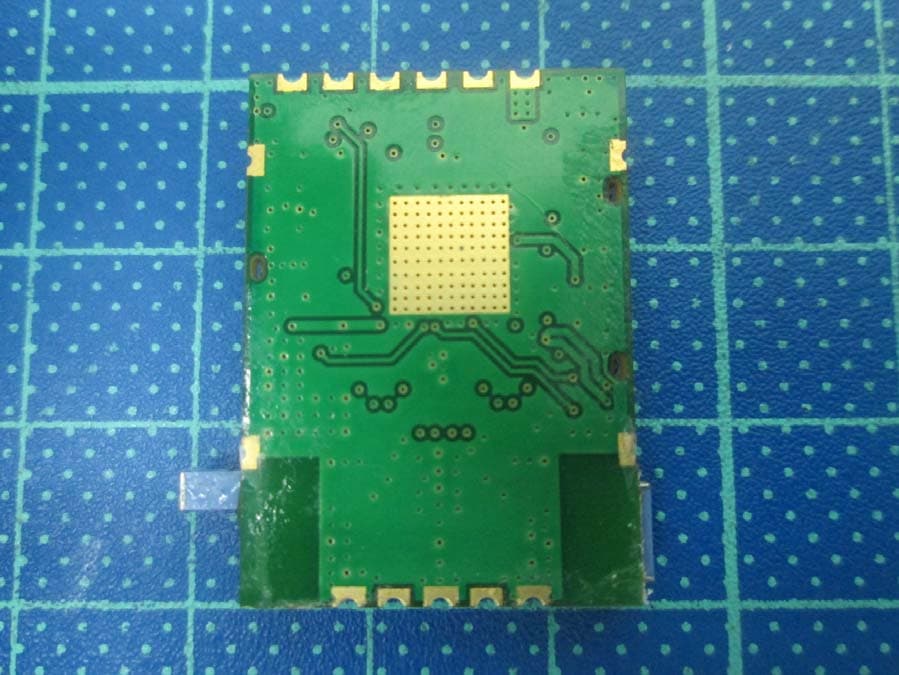
Click to zoom
Application Details
- Equipment Class
- DTS - Digital Transmission System
- Date of Grant
- Jul 05, 2015
- Application Purpose
- Original Equipment
- Date of Application
- Jul 05, 2015
- Equipment Note
- USB WiFi Module
- Frequency Range
- 2412.00000000 - 2462.00000000
- Company
- Radicom Research Inc
- Country
- United States
Documents & Files
Document Text
Text extracted from the exhibit documents filed with the FCC. Open a document above to read the original.
Users Manual
Radicom Research, Inc. Preliminary Designer’s Guide for the WiFiHU2S-a/c RoHS Compliant SMD WiFi Modules June 30, 2015 2 Table of Contents Introduction and Features 3 Ratings and Block Diagram 4 Model and Ordering Information 5 Connecting the WiFiHU2S to Your System 6 General Layout Design Suggestions 7 WiFiHU2S Module Mechanical Dimension 8 WiFiHU2S Module Layout Pad Guideline 9 WiFiHU2S Module Pinout Diagram and Definition 10 FCC, IC, and CE Label Location and Module Model Identification 12 Important Regulatory Compliance and User Information 12 CE Declaration of Conformity 15 WiFiHU2S Regulatory Domain Frequencies 16 Driver Installation Guide for Windows XP/2K 17 WiFiHU2S USB Linux Driver Quick Installation Guide 20 WiFiHU2S USB Linux SoftAP Installation 21 Installing the WiFiHU2S in SoftAP Mode for Windows 7 23 Limited Warranty 25 Contacting Radicom Research 27 Information furnished by Radicom Research is believed to be accurate and reliable. However Radicom Research assumes no responsibility for its use, or any infringement of patents or other rights of third parties that may result from its use. Radicom Research reserves the right to change circuitry at any time without notice. This document is subject to change without notice. 3 Introduction Thanks for purchasing Radicom Research’s SMD WiFi Module. Radicom is committed to providing quality service and technical support in order to expedite the product development process. The WiFiHU2S Module is designed to fully support IEEE802.11n™ Draft 2.0, IEEE802.11e™ and IEEE802.11i™ standards. If further information is required, please contact us and we will provide any additional help needed. The WiFiHU2S series offers SoftAP support. It can turn your Internet connected PC or Laptop into a WiFi Wireless Access Point. So any WiFi device such as iPhone, iPod, PDA, within range can connect to Internet by sharing your WiFiHU2S Access Point. The WiFiHU2S-a/c requires significant CPU power to run in SoftAP mode on 802.11n. Unless you have a very powerful CPU, it is recommended to use the SoftAP mode of WiFiHU2S in 802.11b or g modes only. Features SoftAP support (Software enabled Access Point) Supports ACCESS Point (Host WiFi) IEEE 802.11b/g/n compatible WLAN 150Mbps receive PHY rate and 75Mbps transmit PHY rate using 20MHz bandwidth 300Mbps receive PHY rate and 150Mbps transmit PHY rate using 40MHz bandwidth 20MHz and 40MHz bandwidth transmission Operates in 2.4GHz Frequency Range Compatible with 802.11n draft 2.0 specification Backward compatible with 802.11b/g devices while operating at 802.11n data rates Frame aggregation for increased MAC efficiency (A-MSDU, A-MPDU) Low latency immediate High-Throughput Block Acknowledgement (HT-BA) Long NAV for media reservation with CF-End for NAV release PHY-level spoofing to enhance legacy compatibility Hardware antenna diversity Channel management and co-existence Multiple BSSID feature allows multiple MAC identities when used as a wireless bridge Supports Wake-On-WLAN via Magic Packet and Wake-up frame Transmit Opportunity (TXOP) Short Inter-Frame Spaces (SIFS) bursting for higher multimedia bandwidth Short Guard Interval (400ns) DSSS with DBPSK and DQPSK, CCK modulation with long and short preamble OFDM with BPSK, QPSK, 16QAM, and 64QAM modulation Convolutional Coding Rate: 1/2, 2/3, 3/4, and 5/6 OFDM receive diversity with MRC using up to 2 receive paths. Switch diversity used for DSSS/CCK Selectable digital transmit and receive FIR filters Programmable scaling in transmitter and receiver to trade quantization noise against increased probability of clipping Fast receiver Automatic Gain Control (AGC) 4 Approvals (PENDING) FCC Part 15: FCC OET 65 Supplement C (SAR), 47 CFR FCC Part 15 Subpart C 15.247, 47 CFR FCC Part 15 Subpart B 2009 (Class B) IC RSS-102, IC ES-003 issue 4, IC RSS-247 issue 1:2015 RoHS Compliant CE Marked: EN 61000-3-2:2006+A2:2009, EN 62311:2008, EN 300 328 V1.7.1, EN 301 489-1, V1.8.1, EN 61000-3-3:2008, EN 301 489-17 V2.1.1) EN 60950-1:2006+A11:2009+A1:2010+A12:2011 Support IEEE 802.11b/g/n compatible WLAN IEEE 802.11e QoS Enhancement (WMM) IEEE 802.11h TPC, Spectrum Measurement IEEE 802.11i (WPA, WPA2, WEP). Security ~ Open, shared key, and pair-wise key authentication services Ratings Parameter Min Typical Max Units Maximum Data Rate 300M bps Operating Temperature HU -40 +85 C Relative Humidity (non-condensing) 5 % 95 % Operating Voltage 3.15 3.3 3.6 V Current Consumption 155 160 168 mA Transmit & Receive Level -84(Rx) +17 (Tx) dBm Block Diagram MAC RF USB Interface SMD MODULE GND Antennas 5 Model and Ordering Information This versatile WiFiHU2S family of products offers configuration options to meet the specific system. The WiFiHU2S is available as a SMD module with antennas interface. The WiFiHU2S also has many different antennas options. *These models can use either one or two cables and antennas. For ultimate performance, we recommend using two antennas with better adaptability for receiving. If user want to use only one set of cable and Antenna, try to use CON1 first. Model Description Comments WiFiHU2S-a WiFi SMD Module with dual on board chip antennas Uses onboard chip antennas. Not for use with External Antenna. WiFiHU2S-c * WiFi SMD Module with dual on board U.FL connectors for attaching antenna cables and 2.4GHz 2 dBi Omni-directional antennas Allows designer to determine antenna placement. Can use one or two cables and antennas AC6i-RP-SMA 6" U.FL. to RP-SMA female connector antenna cable Antenna Cable for model WiFiHU2S-c ATN-2d-RP-SMA Replacement antenna, 2.4GHz, 2dBi, RP-SMA, Omni- directional. Antenna for model WiFiHU2S-c 6 Connecting the WiFiHU2S to Your System Prior to connecting the WiFiHU2S to a Window XP, the drivers should be installed. The WiFiHU2S Modules are designed for easy connection to any wireless network. If using Windows, load the provided drivers. The WiFiHU2S is now ready for u…
Text truncated - open the document above for the full version.
Cover Letter(s)
Modular Approval Request Letter FCC ID: K7T-WIFIHU2S Data: June 26, 2015 Gentlemen: There’s that would like to have your authorization as a modular approval. The specific product as below, USB WiFi Module, with its designed features and specified description, meets special requirements for full modular approval on FCC Public Notice DA 00-1407 Released: June 26, 2000 by cross-reference list below. Company: Radicom Research, Inc__ Product Name: USB WiFi Module Model Number WiFiHU2s-a, WiFiHU2s-c FCC No.: K7T-WIFIHU2S Requirement of Public Notice DA00-1407 / part 15.212 Reference to WiFiHU2s-a, WiFiHU2s-c 1. The modular transmitter must have its own RF shielding. The module has its own RF shielding. Please see external photo.pdf 2. The modular transmitter must have buffered modulation/data inputs. The modular has buffered data inputs; it is integrated In chip RTL8192CU. Please see block diagram.pdf 3. The modular transmitter must have its own power supply regulation. All power lines derived from the host device are regulated before energizing other circuits internal to the WiFiHU2s-a and WiFiHU2s-c. Please see circuit.pdf 4. The modular transmitter must comply with the antenna requirements of Section 15.203 and 15.204(c). The WiFiHU2s-a and WiFiHU2s-c meet the IC antenna requirements. It has a unique connector. Please see internal photo.pdf 5. The modular transmitter must be tested in a stand-alone configuration, i.e., the module must not be inside another device during testing. The WiFiHU2s-a and WiFiHU2s-c were tested in a stand-alone configuration via an USB hub PCB. To remove the WiFiHU2s carefully remove it from the six pin headers on the USB interface board. 6. The modular transmitter must be labeled with its own FCC ID number, and, if the FCC ID is not visible when the module is installed inside another device, then the outside of the device into which the module is installed must also display a label referring to the enclosed module. The label position of WiFiHU2s-a and WiFiHU2s-c are clearly indicated. Please see the label location.pdf 7. The modular transmitter must comply with any specific rule or operating requirements applicable to the transmitter and the manufacturer must provide adequate instructions along with the module to explain any such requirements. A copy of these instructions must be included in the application for equipment authorization. The module is compliant with all applicable FCC rules. Detail instructions are given in the Users Manual. Please see Installation guide.pdf 8. The modular transmitter must comply with any applicable RF exposure requirements. For example, FCC Rules in Sections 2.1091, 2.1093 and specific Sections of Part 15, including 15.319(i), 15.407(f), 15.253(f) and 15.255(g), require that Unlicensed PCS, UNII and millimeter wave devices perform routine environmental evaluation for RF Exposure to demonstrate compliance. In addition, spread spectrum transmitters operating under Section 15.247 are required to address RF Exposure compliance in accordance with Section 15.247(b)(4). The WiFiHU2s-a and WiFiHU2s-c comply with applicable RF exposure requirements. Please see MPE report. pdf Yours truly, Roger Sheridan QA Manager Radicom Research Inc
Cover Letter(s)
THIS MUST BE SIGNED BY THE APPLICANT/AGENT AND SHOULD BE PLACED ON APPROPRIATE LETTERHEAD Request for Confidentiality Date: _ 2015/06/26______ Subject: Confidentiality Request for: _____K7T-WIFIHU2S______ Pursuant to FCC 47 CRF 0.457(d) and 0.459 and IC RSP-100, Section 6.4, the applicant requests that a part of the subject FCC application be held confidential. Type of Confidentiality Requested Exhibit Short Term Permanent Block Diagrams Short Term External Photos Short Term Permanent* 1 Internal Photos Short Term Permanent Operation Description/Theory of Operation Short Term Permanent Parts List & Placement/BOM Short Term Permanent Tune-Up Procedure Short Term Permanent Schematics Short Term Test Setup Photos Short Term Permanent* 3 User’s Manual ___ __ Radicom Research Inc______ has spent substantial effort in developing this product and it is one of the first of its kind in industry. Having the subject information easily available to "competition" would negate the advantage they have achieved by developing this product. Not protecting the details of the design will result in financial hardship. Permanent Confidentiality: The applicant requests the exhibits listed above as permanently confidential be permanently withheld from public review due to materials that contain trade secrets and proprietary information not customarily released to the public. Short-Term Confidentiality: The applicant requests the exhibits selected above as short term confidential be withheld from public view for a period of ___180 ___ days from the date of the Grant of Equipment Authorization and prior to marketing. This is to avoid premature release of sensitive information prior to marketing or release of the product to the public. Applicant is also aware that they are responsible to notify ACB in the event information regarding the product or the product is made available to the public. ACB will then release the documents listed above for public disclosure pursuant to FCC Public Notice DA 04-1705. NOTE for Industry Canada Applications: IC currently only distinguishes Permanent Confidentiality exhibits as shown above. Short Term confidentiality is not considered applicable to IC applications. Sincere ly, By: __________________________ ___ _ Roger Sheridan __ (Signature/Title 2 ) (Print name) 1 - The asterisked items (*) require further information to be provided to ACB before permanent confidentiality will be extended to these exhibits. Please refer to FCC KDB 726920 and the specific Document link for D01 found at: https://apps.fcc.gov/oetcf/kdb/forms/FTSSearch ResultPage.cfm?switch=P&id=41731 and review section V regarding EXCEPTIONAL CIRCUMSTANCES. As of the October 2014 version of this document, TCB’s can not authorize these requests. The applicant should petition the FCC by submitting an inquiry as directed. A copy of this inquiry and the FCC’s response must be provided with the application. 2 - Must be signed by applicant contact given for applicant on the FCC site, or by the authorized agent if an appropriate authorized agent letter has been provided. Letters should be placed on appropriate letterhead.
Cover Letter(s)
020415 – 08 Authority to Act as Agent Date: __2015/06/10______ American Certification Body, Inc. 6731 Whittier Avenue Suite C110 McLean, VA 22101 To Whom It May Concern: _____ Intertek Testing Services Taiwan Ltd ______ is authorized to act on our behalf, until otherwise notified, for applications to American Certification Body, Inc. (ACB). We certify that we are not subject to denial of federal benefits, that includes FCC benefits, pursuant to Section 5301 of the Anti-Drug Abuse Act of 1988, 21 U.S.C. 862. Further, no party, as defined in 47 CFR 1.2002 (b), to the application is subject to denial of federal benefits, that includes FCC benefits. Thank you, Agency Agreement Expiration Date: _____June 10, 2016 _____ By: _________ _____ Roger Sheridan (Signature 1 ) (Print name) Title: ___QA Manager _____ On behalf of: ___ Radicom Research, Inc________ (Company Name) Telephone: ___408 383 9006___ 1 - Must be signed by applicant contact given for applicant on the FCC site, or by the authorized agent if an appropriate authorized agent letter has been provided. Letters should be placed on appropriate letterhead.
Cover Letter(s)
Declaration of Identical to Type We declare that the differences of WiFiHU2s‐a and WiFiHU2s‐c are listed as below. Model Number Product Description WiFiHU2s‐a Modules (with on‐ board antenna) SMD type, half‐hole pad to solder to base board WiFiHU2s‐c Modules (with two antenna connectors) SMD type, half‐hole pad to solder to base board WiFiHU2s‐a and WiFiHU2s‐c have the same power setting. July 6, 2015 Roger Sheridan Date of issue Manufacturer/Authorized representative name and signature
External Photos
External photo of EUT WiFiHU2s-a External photo of EUT WiFiHU2s-c
ID Label/Location Info
Model: WiFiHU2s-a FCC ID & IC Label Location S S WiFiHU2s-a Model: WiFiHU2s-c FCC ID & IC Label Location S S WiFiHU2s-c
Internal Photos
Internal photo of EUT WiFiHU2s-a Internal photo of EUT RF module Antenna Internal photo of EUT Antenna Internal photo of EUT WiFiHU2s-c Internal photo of EUT RF module Antenna Internal photo of EUT Antenna Antenna
RF Exposure Info
FCC ID: K7T-WIFIHU2S Report No.: 150500231TWN-001 Page 1 of 13 0597 Maximum Permissible Exposure (MPE) Evaluation Report Report No. : 150500231TWN-001 Model No. : WiFiHU2s-a, WiFiHU2s-c Issued Date : Jun. 02, 2015 Applicant: Radicom Research Inc. 2148 Bering Dr., San Jose, CA. 95131, USA Test Method/ Standard: FCC 1.1310 Test By: Intertek Testing Services Taiwan Ltd. No. 11, Lane 275, Ko-Nan 1 Street, Chia-Tung Li, Shiang-Shan District, Hsinchu City, Taiwan It may be duplicated completely for legal use with the allowance of the applicant. It shall not be reproduced except in full, without the written approval of Intertek Laboratory. The test result(s) in this report only applies to the tested sample(s). The test report was prepared by: Evelyn Lee/ Officer These measurements were taken by: Wayne Chen/ Engineer The test report was reviewed by: Name Jimmy Yang Title Senior Engineer FCC ID: K7T-WIFIHU2S Report No.: 150500231TWN-001 Page 2 of 13 Table of Contents Summary of Tests ..............................................................................................................3 1. General information ......................................................................................................4 1.1 Identification of the EUT ........................................................................................4 1.2 Additional information about the EUT....................................................................5 1.3 Antenna description.................................................................................................6 1.4 Peripherals equipment .............................................................................................6 2. Test specifications .........................................................................................................7 2.1 Introduction .............................................................................................................7 2.2 RF Exposure Limit ..................................................................................................8 2.3 RF Exposure calculations......................................................................................10 2.4 Operation mode .....................................................................................................10 2.5 Test equipment ......................................................................................................11 2.6 Test Set-up .............................................................................................................11 3. Test results ...................................................................................................................12 FCC ID: K7T-WIFIHU2S Report No.: 150500231TWN-001 Page 3 of 13 Summary of Tests MPE Evaluation meet FCC OET No. 65: 1997, IEEE C95.1-2005 Test Reference Results MPE Evaluation FCC Guidelines for Human Exposure IEEE C95.1Complies FCC ID: K7T-WIFIHU2S Report No.: 150500231TWN-001 Page 4 of 13 1. General information 1.1 Identification of the EUT Product: USB WiFi Module Model No: WiFiHU2s-a, WiFiHU2s-c FCC ID: K7T-WIFIHU2S Operating Frequency: 2412 MHz ~ 2462 MHz for 802.11b, 802.11g, 802.11n (HT20) 2422 MHz ~ 2452 MHz for 802.11n (HT40) Channel Number: 11 channels for 2412 MHz ~ 2462 MHz 9 channels for 2422 MHz ~ 2452 MHz Access scheme: DSSS, OFDM Rated Power: DC 5V from Notebook PC Power Cord: N/A Sample Received: May 15, 2015 Sample condition: Workable Test Date(s): May 27, 2015 ~ Jun. 01, 2015 Note 1: This report is for the exclusive use of Intertek's Client and is provided pursuant to the agreement between Intertek and its Client. Intertek's responsibility and liability are limited to the terms and conditions of the agreement. Intertek assumes no liability to any party, other than to the Client in accordance with the agreement, for any loss, expense or damage occasioned by the use of this report. Only the Client is authorized to permit copying or distribution of this report and then only in its entirety. Any use of the Intertek name or one of its marks for the sale or advertisement of the tested material, product or service must first be approved in writing by Intertek. The observations and test results in this report are relevant only to the sample tested. This report by itself does not imply that the material, product, or service is or has ever been under an Intertek certification program. Note 2: When determining the test conclusion, the Measurement Uncertainty of test has been considered. FCC ID: K7T-WIFIHU2S Report No.: 150500231TWN-001 Page 5 of 13 1.2 Additional information about the EUT Transmit path Modulation mode Chain 0 / Main Chain 1 / AUX 802.11b V X 802.11g V V 802.11 n (HT20) V V 802.11 n (HT40) V V Product SW/HW version : SW: V010 / HW: RA6/RA7 Radio SW/HW version : SW: V010 / HW: RA6/RA7 Test SW Version : V010_RTL11n_SingleChip_9xC_USB_v010_20100428 The differences of WiFiHU2s-a and WiFiHU2s-c (EUT) are listed as below. Model Number Product Description WiFiHU2s-a Modules (with on- board antenna) SMD type, half-hole pad to solder to base board Without power regulator circuit WiFiHU2s-c Modules (with two antenna connectors) SMD type, half-hole pad to solder to base board, Without power regulator circuit FCC ID: K7T-WIFIHU2S Report No.: 150500231TWN-001 Page 6 of 13 1.3 Antenna description For WiFiHU2s-a: The EUT uses a permanently connected antenna. Antenna Gain : 0 dBi Antenna Type : Chip antenna Connector Type : Fixed For WiFiHU2s-c: The antenna is affixed to the EUT using a unique connector, which allows for replacement of a broken antenna, but DOES NOT use a standard antenna jack or electrical connector. Antenna Gain : 2 dBi Antenna Type : Dipole antenna Connector Type : I-PEX 1.4 Peripherals equipment Peripherals Brand Model No. Serial No. Data cable Notebook PC DELL Latitude D610 4YWZK1S USB 0.5 meter × 1 FCC ID: K7T-WIFIHU2S Report No.: 150500231TWN-001 Page 7 of 13 2. Test specifications 2.1 Introduction Th…
Text truncated - open the document above for the full version.
Test Report
FCC ID: K7T-WIFIHU2S Report No.: 150500230TWN-001 Page 1 of 104 EMC TEST REPORT Report No. : 150500230TWN-001 Model No. : WiFiHU2s-a, WiFiHU2s-c Issued Date : Jun. 02, 2015 Applicant: Radicom Research Inc. 2148 Bering Dr., San Jose, CA. 95131, USA Test Method/ Standard: 47 CFR FCC Part 15.247 & ANSI C63.4 2009 KDB 558074 D01 v03r03 Test Site: 93910 Test By: Intertek Testing Services Taiwan Ltd. No. 11, Lane 275, Ko-Nan 1 Street, Chia-Tung Li, Shiang-Shan District, Hsinchu City, Taiwan It may be duplicated completely for legal use with the allowance of the applicant. It shall not be reproduced except in full, without the written approval of Intertek Laboratory. The test result(s) in this report only applies to the tested sample(s). The test report was prepared by: Evelyn Lee/ Officer These measurements were taken by: Wayne Chen/ Engineer The test report was reviewed by: Name Jimmy Yang Title Senior Engineer FCC ID: K7T-WIFIHU2S Report No.: 150500230TWN-001 Page 2 of 104 Table of Contents 1. Summary of Test Data................................................................................................................. 4 2. General Information.................................................................................................................... 5 2.1 Identification of the EUT ...................................................................................................... 5 2.2 Description of EUT............................................................................................................... 6 2.3 Antenna description .............................................................................................................. 7 2.4 Peripherals equipment........................................................................................................... 7 2.5 Operation mode..................................................................................................................... 8 2.6 Applied test modes and channels ........................................................................................ 11 2.7 Power setting of test software .............................................................................................12 3. Minimum 6 dB Bandwidth ....................................................................................................... 14 3.1 Operating environment ....................................................................................................... 14 3.2 Limit for minimum 6dB bandwidth .................................................................................... 14 3.3 Measuring instrument setting.............................................................................................. 14 3.4 Test procedure ..................................................................................................................... 14 3.5 Test diagram ........................................................................................................................ 15 3.6 Test results........................................................................................................................... 15 4. Maximum Peak Conducted Output Power ............................................................................... 31 4.1 Operating environment ....................................................................................................... 31 4.2 Limit for maximum peak conducted output power............................................................. 31 4.3 Measuring instrument setting.............................................................................................. 31 4.4 Test procedure ..................................................................................................................... 31 4.5 Test diagram ........................................................................................................................ 31 4.6 Test result ............................................................................................................................ 32 5. Power Spectral Density............................................................................................................. 34 5.1 Operating environment ....................................................................................................... 34 5.2 Limit for power spectrum density....................................................................................... 34 5.3 Measuring instrument setting.............................................................................................. 34 5.4 Test procedure ..................................................................................................................... 35 5.5 Test diagram ........................................................................................................................ 35 5.6 Test results........................................................................................................................... 35 6. Emissions In Non-Restricted Frequency Bands ....................................................................... 51 6.1 Operating environment ....................................................................................................... 51 6.2 Limit for emissions in non-restricted frequency bands....................................................... 51 FCC ID: K7T-WIFIHU2S Report No.: 150500230TWN-001 Page 3 of 104 6.3 Measuring instruments setting ............................................................................................ 51 6.4 Test procedure ..................................................................................................................... 52 6.5 Test diagram ........................................................................................................................ 52 6.6 Test results................................................................................................…
Text truncated - open the document above for the full version.
Test Report
FCC ID: K7T-WIFIHU2S Report No.: 150500230TWN-001 Page 51 of 104 6. Emissions In Non-Restricted Frequency Bands 6.1 Operating environment Temperature: 25 °C Relative Humidity: 50 % Atmospheric Pressure 1008 hPa Requirement 15.247(d) Channel number 1、6、11 6.2 Limit for emissions in non-restricted frequency bands The peak output power measured in any 100 kHz bandwidth outside of the authorized frequency band shall be attenuated by at least 20 dB relative to the maximum in-band peak PSD level in 100 kHz 6.3 Measuring instruments setting Reference level measurement Spectrum analyzer settings Spectrum Analyzer function Setting Detector Peak RBW ≧100 kHz VBW ≧3 x RBW Sweep Auto couple Trace Max hold Span ≧1.5 time 6dB bandwidth Attenuation Auto FCC ID: K7T-WIFIHU2S Report No.: 150500230TWN-001 Page 52 of 104 Emission level measurement Spectrum analyzer settings Spectrum Analyzer function Setting Detector Peak RBW ≧100 kHz VBW ≧3 x RBW Sweep Auto couple Trace Max hold Attenuation Auto 6.4 Test procedure 1. The procedure was used in antenna-port conducted and connected to the spectrum analyzer. 2. Set instrument center frequency to center frequency 3. Use the parameter configured in clause 6.3 to measure 4. Use the peak marker function to determine the maximum amplitude level. 6.5 Test diagram Power meter Attenuator & DC block Power supply EUT FCC ID: K7T-WIFIHU2S Report No.: 150500230TWN-001 Page 53 of 104 6.6 Test results For WiFiHU2s-a: Chain0 : Conducted Spurious @ 802.11b mode Ch 1 Chain0 : Conducted Spurious @ 802.11b mode Ch 1 Chain0 : Conducted Spurious @ 802.11b mode Ch 6 FCC ID: K7T-WIFIHU2S Report No.: 150500230TWN-001 Page 54 of 104 Chain0 : Conducted Spurious @ 802.11b mode Ch 6 Chain0 : Conducted Spurious @ 802.11b mode Ch11 Chain0 : Conducted Spurious @ 802.11b mode Ch11 FCC ID: K7T-WIFIHU2S Report No.: 150500230TWN-001 Page 55 of 104 Chain0 : Conducted Spurious @ 802.11g mode Ch 1 Chain0 : Conducted Spurious @ 802.11g mode Ch 1 Chain0 : Conducted Spurious @ 802.11g mode Ch 6 FCC ID: K7T-WIFIHU2S Report No.: 150500230TWN-001 Page 56 of 104 Chain0 : Conducted Spurious @ 802.11g mode Ch 6 Chain0 : Conducted Spurious @ 802.11g mode Ch11 Chain0 : Conducted Spurious @ 802.11g mode Ch11 FCC ID: K7T-WIFIHU2S Report No.: 150500230TWN-001 Page 57 of 104 Chain1 : Conducted Spurious @ 802.11g mode Ch 1 Chain1 : Conducted Spurious @ 802.11g mode Ch 1 Chain1 : Conducted Spurious @ 802.11g mode Ch 6 FCC ID: K7T-WIFIHU2S Report No.: 150500230TWN-001 Page 58 of 104 Chain1 : Conducted Spurious @ 802.11g mode Ch 6 Chain1 : Conducted Spurious @ 802.11g mode Ch11 Chain1 : Conducted Spurious @ 802.11g mode Ch11 FCC ID: K7T-WIFIHU2S Report No.: 150500230TWN-001 Page 59 of 104 Chain0 : Conducted Spurious @ 802.11n(HT20) mode Ch 1 Chain0 : Conducted Spurious @ 802.11n(HT20) mode Ch 1 Chain0 : Conducted Spurious @ 802.11n(HT20) mode Ch 6 FCC ID: K7T-WIFIHU2S Report No.: 150500230TWN-001 Page 60 of 104 Chain0 : Conducted Spurious @ 802.11n(HT20) mode Ch 6 Chain0 : Conducted Spurious @ 802.11n(HT20) mode Ch11 Chain0 : Conducted Spurious @ 802.11n(HT20) mode Ch11 FCC ID: K7T-WIFIHU2S Report No.: 150500230TWN-001 Page 61 of 104 Chain1 : Conducted Spurious @ 802.11n(HT20) mode Ch 1 Chain1 : Conducted Spurious @ 802.11n(HT20) mode Ch 1 Chain1 : Conducted Spurious @ 802.11n(HT20) mode Ch 6 FCC ID: K7T-WIFIHU2S Report No.: 150500230TWN-001 Page 62 of 104 Chain1 : Conducted Spurious @ 802.11n(HT20) mode Ch 6 Chain1 : Conducted Spurious @ 802.11n(HT20) mode Ch11 Chain1 : Conducted Spurious @ 802.11n(HT20) mode Ch11 FCC ID: K7T-WIFIHU2S Report No.: 150500230TWN-001 Page…
Text truncated - open the document above for the full version.
Contact Information
Applicant
James Sun(QC/Project Manager)
Test Firm
Intertek Testing Services Taiwan Ltd.Lily Shih
Technical Specifications
| # | Rule Parts | Frequency Range | Power Output |
|---|---|---|---|
| 1 | 15C | 2.41 GHz - 2.46 GHz | 361.00 mW |
Other Applications from Radicom Research Inc
K7T-RW8300M
Feb 09, 20202.4G WiFi+BT4.2(BLE) module
Equipment Class
DTS - Digital Transmission System
K7T-BPM730CE
Apr 28, 201420730 class 2 Bluetooth Module
Equipment Class
DSS - Part 15 Spread Spectrum Transmitter
K7T-RW8200
Mar 19, 2014RW8200 Serial / USB Embedded WiFi Modules
Equipment Class
DTS - Digital Transmission System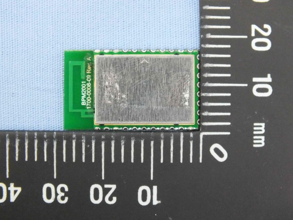
K7T-BPM2001
Sep 15, 2013CSR8311 BlueTooth Module
Equipment Class
DTS - Digital Transmission System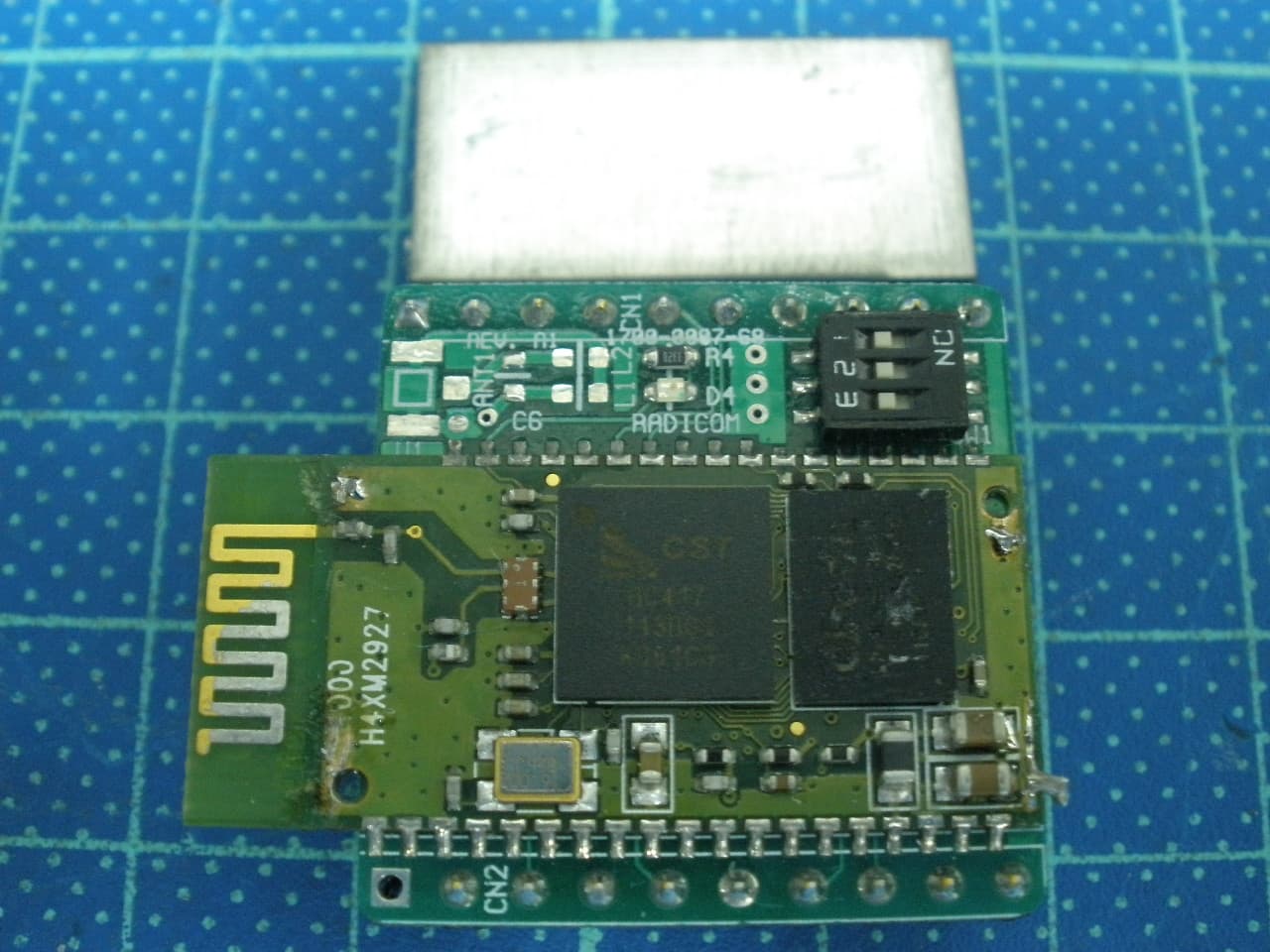
K7T-RB4000
May 30, 2012Bluetooth Module
Equipment Class
DSS - Part 15 Spread Spectrum Transmitter