K8C1208CLBLevel and Flow Transmitter
Rosemount Tank Radar AB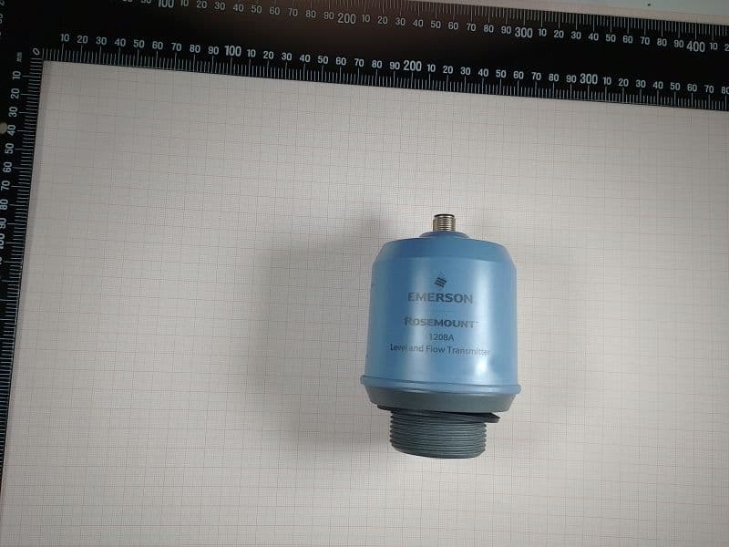
Click to zoom
Application Details
- Equipment Class
- LPR - Level Probing Radar
- Date of Grant
- May 09, 2023
- Application Purpose
- Original Equipment
- Date of Application
- May 09, 2023
- Equipment Note
- Level and Flow Transmitter
- Frequency Range
- 77000.00000000 - 81000.00000000
- Company
- Rosemount Tank Radar AB
- Country
- Sweden
Documents & Files
Document Text
Text extracted from the exhibit documents filed with the FCC. Open a document above to read the original.
Users Manual
Reference Manual 00809-0200-7062, Rev AA March 2023 Rosemount ™ 1208C Level and Flow Transmitter Non-Contacting Radar Safety messages NOTICE Read this manual before working with the product. For personal and system safety, and for optimum product performance, make sure you thoroughly understand the contents before installing, using, or maintaining this product. For technical assistance, contacts are listed below: Customer Central Technical support, quoting, and order-related questions. • United States - 1-800-999-9307 (7:00 am to 7:00 pm CST) • Asia Pacific- 65 777 8211 North American Response Center Equipment service needs. • 1-800-654-7768 (24 hours a day — includes Canada) • Outside of these areas, contact your local Emerson representative. WARNING Failure to follow safe installation and servicing guidelines could result in death or serious injury. Ensure the transmitter is installed by qualified personnel and in accordance with applicable code of practice. Inspection and maintenance of this equipment shall be carried out by suitably trained personnel, in accordance with the applicable standards and code of practice. Use the equipment only as specified in this manual. Failure to do so may impair the protection provided by the equipment. Repair, e.g. substitution of components, etc. may jeopardize safety and is under no circumstances allowed. WARNING Explosions could result in death or serious injury. To prevent ignition of flammable or combustible atmospheres, disconnect power before servicing. Before connecting a handheld communicator in an explosive atmosphere, ensure that the instruments are installed in accordance with intrinsically safe or non-incendive field wiring practices. WARNING Process leaks could result in death or serious injury. Handle the transmitter carefully. Install and tighten process connectors before applying pressure. Do not attempt to loosen or remove process connectors while the transmitter is in service. WARNING Physical access Unauthorized personnel may potentially cause significant damage to and/or misconfiguration of end users’ equipment. This could be intentional or unintentional and needs to be protected against. Physical security is an important part of any security program and fundamental in protecting your system. Restrict physical access by unauthorized personnel to protect end users’ assets. This is true for all systems used within the facility. 2 CAUTION Hot surfaces The transmitter and process seal may be hot at high process temperatures. Allow to cool before servicing. 3 4 Contents Chapter 1 Introduction...............................................................................................................................7 1.1 Using this manual........................................................................................................................7 1.2 Product certifications..................................................................................................................7 1.3 Open source licenses..................................................................................................................7 1.4 Product recycling/disposal.........................................................................................................7 Chapter 2 Transmitter overview...............................................................................................................9 2.1 Measurement principle...............................................................................................................9 2.2 Process characteristics................................................................................................................9 2.3 Vessel characteristics................................................................................................................10 2.4 Non-contacting radar technology...........................................................................................10 2.5 Components of the transmitter...............................................................................................12 2.6 System integration....................................................................................................................13 Chapter 3 Mechanical installation..........................................................................................................15 3.1 Safety messages........................................................................................................................15 3.2 Installation considerations.......................................................................................................15 3.3 Bracket mounting......................................................................................................................19 3.4 Installing on a tank....................................................................................................................26 Chapter 4 Electrical installation..............................................................................................................29 4.1 Safety messages........................................................................................................................29 4.2 Prepare the electrical connections..........................................................................................29 4.3 Power up transmitter................................................................................................................31 4.4 Optional devices........................................................................................................................31 Chapter 5 Configuration.......................................................................................................................... 33 5.1 Safety messages........................................................................................................................33 5.2 Overview.............................................…
Text truncated - open the document above for the full version.
Users Manual
Regulatory information Telecommunication compliance LPR (Level Probing Radar) equipment are devices for measurement of level in the open air or in a closed space. TLPR (Tank Level Probing Radar) equipment are devices for measurement of level in a closed space only (i.e metallic, concrete or reinforced fiberglass tanks, or similar enclosure structures made of comparable attenuating material). Hardware Version Identification Number (HVIN) is 1208CL1 or 1208CLB1 (without or with Bluetooth). Measurement principle Frequency Modulated Continuous Wave (FMCW), 80 GHz Maximum output power 3 dBm (2 mW) Frequency range 77 to 81 GHz FCC Note: This equipment has been tested and found to comply with the limits for a Class B digital device, pursuant to part 15 of the FCC Rules. These limits are designed to provide reasonable protection against harmful interference in a residential installation. This equipment generates, uses and can radiate radio frequency energy and, if not installed and used in accordance with the instructions, may cause harmful interference to radio communications. However, there is no guarantee that interference will not occur in a particular installation. If this equipment does cause harmful interference to radio or television reception, which can be determined by turning the equipment off and on, the user is encouraged to try to correct the interference by one or more of the following measures: — Reorient or relocate the receiving antenna. — Increase the separation between the equipment and receiver. — Connect the equipment into an outlet on a circuit different from that to which the receiver is connected. — Consult the dealer or an experienced radio/TV technician for help. FCC ID K8C1208CL (for LPR/TLPR without Bluetooth) FCC ID K8C1208CLB (for LPR/TLPR with Bluetooth) IC This device complies with Industry Canada’s licence-exempt RSS standard. Operation is subject to the following conditions: 1. This device may not cause harmful interference. 2. This device must accept any interference received, including interference that may cause undesired operation. 3. The installation of the LPR/TLPR device shall be done by trained installers in strict compliance with the manufacturer’s instructions. 4. The use of this device is on a “no-interference, no-protection” basis. That is, the user shall accept operations of high- powered radar in the same frequency band which may interfere with or damage this device. However, devices found to interfere with primary licensing operations will be required to be removed at the user’s expense. 5. The installer/user of this device shall ensure that it is at least 10 km from the Dominion Astrophysical Radio Observatory (DRAO) near Penticton, British Columbia. The coordinates of the DRAO are latitude 49°19′15′′N and longitude 119°37′12′′ W. For devices not meeting this 10 km separation (e.g., those in the Okanagan Valley, British Columbia,) the installer/user must coordinate with, and obtain the written concurrence of, the Director of the DRAO before the equipment can be installed or operated. The Director of the DRAO may be contacted at 250-497-2300 (tel.) or 250-497-2355 (fax). (Alternatively, the Manager, Regulatory Standards, Industry Canada, may be contacted.) Le présent appareil est conforme aux CNR d'Industrie Canada applicables aux appareils radio exempts de licence. L'exploitation est autorisée aux conditions suivantes: 1. l'appareil ne doit pas produire de brouillage. 2. l'appareil doit accepter tout brouillage radioélectrique subi, même si le brouillage est susceptible d'en compromettre le fonctionnement. 3. L’installation d’un dispositif LPR/TLPR doit être effectuée par des installateurs qualifiés, en pleine conformité avec les instructions du fabricant. 4. Ce dispositif ne peut être exploité qu'en régime de non-brouillage et de non-protection, c'est-à-dire que l'utilisateur doit accepter que des radars de haute puissance de la même bande de fréquences puissent brouiller ce dispositif ou même l'endommager. D'autre part, les capteurs de niveau qui perturbent une exploitation autorisée par licence de fonctionnement principal doivent être enlevés aux frais de leur utilisateur. 5. La personne qui installe/utilise ce capteur de niveau doit s'assurer qu'il se trouve à au moins 10 km de l'Observatoire fédéral de radioastrophysique (OFR) de Penticton en Colombie-Britannique. Les coordonnées de l'OFR sont: latitude N 49° 19′ 15′′, longitude O 119° 37′ 12′′. La personne qui installe/utilise un dispositif ne pouvant respecter cette distance de 10 km (p. ex. dans la vallée de l'Okanagan [Colombie-Britannique]) doit se concerter avec le directeur de l'OFR afin d’obtenir de sa part une autorisation écrite avant que l'équipement ne puisse être installé ou mis en marche. Le directeur de l'OFR peut être contacté au 250-497-2300 (tél.) ou au 250-497-2355 (fax). (Le Directeur des Normes réglementaires d'Industrie Canada peut également être contacté). Certificate: 2827A-1208CL (for LPR/TLPR without Bluetooth) 2827A-1208CLB (for LPR/TLPR with Bluetooth)
Users Manual
Quick Start Guide 00825-0200-7062, Rev AA February 2023 Rosemount ™ 1208C Level and Flow Transmitter Non-Contacting Radar Contents About this guide...........................................................................................................................3 Installing on a tank......................................................................................................................5 Prepare the electrical connections............................................................................................8 Power up transmitter................................................................................................................10 Configuration.............................................................................................................................11 Quick Start GuideFebruary 2023 2Rosemount 1208C Level and Flow Transmitter 1 About this guide This Quick Start Guide provides basic guidelines for the Rosemount 1208C Level and Flow Transmitter. Refer to the 1208C Reference Manual for more instructions. 1.1 Safety messages WARNING Failure to follow safe installation and servicing guidelines could result in death or serious injury. Ensure the transmitter is installed by qualified personnel and in accordance with applicable code of practice. Use the equipment only as specified in this Quick Start Guide and the Reference Manual. Failure to do so may impair the protection provided by the equipment. Repair, e.g. substitution of components, etc. may jeopardize safety and is under no circumstances allowed. WARNING Explosions could result in death or serious injury. To prevent ignition of flammable or combustible atmospheres, disconnect power before servicing. Before connecting a handheld communicator in an explosive atmosphere, ensure that the instruments are installed in accordance with intrinsically safe or non-incendive field wiring practices. WARNING Process leaks could result in death or serious injury. Handle the transmitter carefully. Install and tighten process connectors before applying pressure. Do not attempt to loosen or remove process connectors while the transmitter is in service. February 2023Quick Start Guide Quick Start Guide3 WARNING Physical access Unauthorized personnel may potentially cause significant damage to and/or misconfiguration of end users’ equipment. This could be intentional or unintentional and needs to be protected against. Physical security is an important part of any security program and fundamental to protecting your system. Restrict physical access by unauthorized personnel to protect end users’ assets. This is true for all systems used within the facility. CAUTION Hot surfaces The transmitter and process seal may be hot at high process temperatures. Allow to cool before servicing. 1.2 Bracket mounting See the documentation supplied with the bracket kit. Quick Start GuideFebruary 2023 4Rosemount 1208C Level and Flow Transmitter 2 Installing on a tank 2.1 Mount the flange Procedure 1. Place a suitable gasket on the tank flange. 2. Place the flange over the gasket. 3. Tighten the bolts and nuts with sufficient torque for the flange and gasket choice. 4. Apply appropriate thread sealant to the transmitter threads. Note Only for NPT threaded tank connection. February 2023Quick Start Guide Quick Start Guide5 5. Install and hand tighten the transmitter. Note The gasket is necessary for the G threaded version only. 2.2 Mount the NPT threaded adapter Procedure 1. Apply appropriate thread sealant to the outer threads. 2. Mount the threaded adapter on the tank. 60 mm Quick Start GuideFebruary 2023 6Rosemount 1208C Level and Flow Transmitter 3. Apply appropriate thread sealant to the transmitter threads. 4. Install and hand tighten the transmitter. February 2023Quick Start Guide Quick Start Guide7 3 Prepare the electrical connections 3.1 Connector type M12 male (A-coded) 3.2 Cable selection Use 24-18 AWG wire (0.20-0.75 mm 2 ). Twisted pairs and shielded wiring are recommended for environments with high EMI (electromagnetic interference). 3.3 Internal power consumption < 0.8 W in normal operation 3.4 Cable shield grounding Make sure the instrument cable shield is: • Continuously connected throughout the segment. • Connected to a good earth ground at the power supply end. 3.5 Power supply The transmitter operates on 14-35 Vdc at the transmitter terminals. 3.6 Load limitations For HART ® communication, a minimum loop resistance of 250 Ω is required. Maximum loop resistance (R) is determined by the voltage level of the external power supply (U E ): R = 44.4 × (U E − 14) Quick Start GuideFebruary 2023 8Rosemount 1208C Level and Flow Transmitter Figure 3-1: Load Limits R (Ω) U E (Vdc) 444 250 930 143524 19.6 0 200 400 600 800 3.7 Wiring diagram Figure 3-2: Connection 4 1 3 2 BN WH BK BU 1 4 2 3 NC L+ L NC Table 3-1: Pin Assignment Pin Wire color (1) Signal 1BN BrownL+24 V 2WH WhiteNCNot connected 3BU BlueL-0 V 4BK BlackNCNot connected (1)According to IEC 60947-5-2. February 2023Quick Start Guide Quick Start Guide9 4 Power up transmitter Procedure 1. Verify the power supply is disconnected. 2. Insert the M12 connector gently. Note Do not force the connector into place. Check that it is aligned properly. 3. Once fully inserted, turn the screw ring until tight. See the manufacturer’s instruction manual for recommended torque. 4. Connect the power supply. Quick Start GuideFebruary 2023 10Rosemount 1208C Level and Flow Transmitter 5 Configuration 5.1 Configuration tools • Field Device Integration (FDI) compliant systems • Device Descriptor (DD) compliant systems • Device Type Manager (DTM ™ ) compliant systems (pending) 5.2 Download AMS Device Configurator AMS Device Configurator is a software for configuration of Emerson field devices using FDI technology. Procedure Download the software at Emerson.com/AMSDeviceConfigurator. 5.3 Confirm correct device driver Procedure 1. Verify that the correct FDI/DD/DTM Package is loaded on …
Text truncated - open the document above for the full version.
Attestation Statements
EMERSON .. Emerson Automation Solutions Rosemount Tank Radar AB P.O. Box 150 SE-435 23 Molnlycke Sweden T +46 31 337 00 00 E [email protected] www.emerson.com/rosemount VAT no SE556043512401 Federal Communication Commission Authorization and Evaluation Division 7435 Oakland Mills Road C olumbia, MD 21046 USA May 3 rd , 2023 Attestation Statement according to 2.911{d){S)(i) and 2.911(d)(S)(ii) F CC ID: I(8C1208CLB TO WHOM IT MAY CONCERN: Hereby we certify that the equipment for which authorization is sought is not "covered" equipment prohibited from receiving an equipment authorization pursuant to section 2.903 of the FCC rules. Further we certify that, as of the date of the filing of the application, Rosemount Tank Radar AB is not identified on the Covered List as an entity producing "covered" equipment. Sincerely, m� (signature & c0mpany stamp) Rosemount Tank Radar AB FCC Registration Number-FRN 0025969163 Layoutvagen 1, 43533 Molnlycke, Sweden Andrei Stefanescu +463133 70343 [email protected]
Attestation Statements
EMERSON .. Emerson Automation Solutions Rosemount Tank Radar AB P.O. Box 150 SE-435 23 Molnlycke Sweden T +46 31 337 00 00 E info. [email protected] www.emerson.com/rosemount VAT no SE556043512401 Federal Communication Commission Authorization and Evaluation Division 7 435 Oakland Mills Road Columbia, MD 21046 USA Ma rch 3 rd 2 023 Attestation Statement according to 2.911(d)(7) FCCID: K8C1208CLB TO W HOM IT MAY CONCERN: We, Rosemount Tank Radar AB with FRN 0025969163, designate Randon Beuc to act as U.S. agent for service of process. Rosemount, Inc with FCC Registration Number (FRN} 0017340878 hereby acknowledges the obligation of the U.S. agent for service of process. Further Rosemount Tank Radar AB accepts to maintain an agent for no less than one year after the grantee has terminated all marketing and importation or the conclusion of an Commission-related proceeding involving the equipment. Sincere! �I pany stamp) Rosemount Tank Radar AB Layoutvagen 1, 43533 Molnlycke, Sweden Andrei Stefanescu +463313370343 [email protected] Rosemount, Inc. 8200 Markel Blvd; 55317 Chanhassen; M innesota 952-204-4432 [email protected]
Cover Letter(s)
Document Version 1.1 2020-10-30 LONG-TERM CONFIDENTIALITY REQUEST for Certification Service in the USA Federal Communication Commission Equipment Authorization Division, Application Processing Branch 7435 Oakland Mills Road Columbia, MD 21048 TO WHOM IT M AY CONCERN Pursuant to Paragraphs §0.457 and 0.459 of the Commission’s Rules (47 C.F.R.) and Section §552(b)(4) of the Freedom of Information Act, we request Long-Term Confidentiality for the following product: For the product stated above, we request Long-Term Confidentiality for exhibits which contain Block Diagram, Operational Description, Parts List/Tune Up Info, Schematics, SDR Software/Security Info. The above exhibits contain ou r trade secrets and proprietary information that could be of benefit to o ur competitors. This information will not be publicly available. If you have any questions, please feel free to contact us at the address shown below. Sincerely, Company Name: Phone: Company Address: Fax: E-mail: Contact Name: Signature: Signature Date: Check your GC here. Click Grantee Search. FCC I D: Grantee Code Equipment Product Code
External Photos
Annex A No.1-3759/21-03 -01_Annex_A External photos of the Device Under Test This document is electronically signed and valid without handwritten signature. For verification of the electronic signatures, the public keys can be requested at the testing laboratory. Document authorized: Thomas Vogler Lab Manager Radio Communications CTC advanced GmbHUntertuerkheimer Str. 6-10 66117 Saarbruecken / Germany Phone: +49 681 5 98 - 0 Fax: +49 681 5 98 - 9075 web: ctcadvanced.com e-mail: [email protected] Photos Annex A Photo 1 Photo 2 2022-07-14 Document 1-3759/21-03-01_Annex_A 2/4 Photo 3 Photo 4 2022-07-14 Document 1-3759/21-03-01_Annex_A 3/4 Photo 5 - END OF DOCUMENT - 2022-07-14 Document 1-3759/21-03-01_Annex_A 4/4
ID Label/Location Info
1 B ORIGINALFORMAT A3 A 1 23 C B 23 A C 1:1 LAYOUTVÄGEN 1, 435 33 MÖLNLYCKE , SWEDEN A3 1 ST ANGLE THE COPYRIGHT/OWNERSHIP OF THIS DOCUMENT IS AND WILL REMAIN OURS. THE DOCUMENT MUST NOT BE USED WITHOUT AUTHORIZATION OR BROUGHT TO THE KNOWLEDGE OF A THIRD PARTY. CONTRAVENTION WILL BE PROSECUTED. ROSEMOUNT TANK RADAR AB, SWEDEN UNLESS OTHERWISE SPECIFIED: ALL DIMENSIONS ARE IN MILLIMETERS. REMOVE ALL BURRS AND SHARP EDGES. - GENERAL TOLERANCES - MACHINING: CASTING: WELDING: ISO 2768 ISO 8062 EN-ISO 13920 FINISH: SCALE TITLE DRAWING NO. ISSUE SHEET ISSUED BY APPROVED BY APP'D WEEK DRAWN WEEK PRODUCT CODE DOC TYPE ANGLES: Adobe Illustrator DO NOT SCALE PRINT PC-AA 23031208 6 01 1/2 D7000007-910 D7000007-910 REVISION DESCRIPTION ECO NO.APP'DDATE 01 SME-11379 EAp-AS2303 ISSUED PC-AA ROSEMOUNT 1208C EX CERT LABEL DRAWING 1208C EX CERTIFICATION LABEL DRAWING EAp-AS 2303 FM APPROVED PRODUCT. No revisions to this drawing without prior Factory Mutual Approval. 1. LABEL TO BE CUSTOMIZED ACCORDING TO FLEX CONTROLLED FIELDS 2. ALL APPROVAL LOGOS IN ACC. WITH RESP. LOGOTYPE. NO. FIELD MODEL PART NO. PART. REV. MARKING FORMAT 1. BASE LAYER 1208A,1208C -0001 AA According to base layer artwork illustration 2.CONNECTION ` DIAGRAM 3. WARNING 1208C -0301 AA 4. LOGOS 1208C -0401 AA 6. SUPPLY 1208C -0502 AA 1208C -0602 AB NO. FIELD SITE PART NO. MARKING FORMAT EXAMPLE FORMAT A MODEL ALL -FLEX<MODEL> 1208XX B SERIAL NO. ALL -FLEX <YYAABC1234567>22BKRL0011234 C PRODUCTION ALL -FLEX<MM-YYYY> 03-2022 DATE D QR CODE ALL -FLEX <QR-CODE> LINKED TO MY ASSETS 1208C -0202AA 1208C -0002 AA According to base layer artwork illustration 1208C -0704AB 7. MADE IN 1208C -0703AB SUBSTITUTION OF COMPONENTS MAY IMPAIR INTRINSIC SAFETY. TO PREVENT IGNITION OF FLAMMABLE OR COMBUSTIBLE ATMOSPHERES, DISCONNECT POWER BEFORE SERVICING. INSTALL PER CONTROL DRAWING LA SUBSITUTION DE COMPOSANTS PEUT COMPROMETTRE LA SÉCURITÉ INTRINSÈQUE. POUR ÉVITER L’ALLUMANGE DE PRODUITS INFLAMMABLES OU ATMOSPHÈRES COMBUSTIBLES, DÉBRANCHEZ L’ALIMENTATION AVANT L’ENTRERIEN INSTALLER SELON LE SCHÉMA DE CONTRÔLE HART® 4-20 mA 14-35 VDC 22.5mA 8501 2460 4 1 3 2 BN WH BK BU 1 4 2 3 NC L+ L NC 泰国制造 Made in Thailand 8. RADIO OUT. Rosemount™ 1208C Level and Flow Transmitter 1208C English 7000007-429 1208CN Rosemount™ 1208CN Level and Flow Transmitter 1208C Chinese 7000007-431 1208CNC Rosemount™ 1208C Level and Flow Transmitter 1208C English 7000007-428 1208CG Rosemount™ 1208CG Level and Flow Transmitter 1208C Chinese 7000007-430 1208CGC Description product variant Model Language Part Number Model string English LANGUAGE Chinese All All All All All English Chinese K8C1208CLB 2827A-1208CLB 1208CLB1 1208C BT -0903AA All K8C1208CL 2827A-1208CL 1208CL1 1208C -0904AA All 5. LOGOS STRING CONTROLLED FIELDS FLEX CONTROLLED FIELDS 1 B ORIGINALFORMAT A3 A 1 23 C B 23 A C 1:1 LAYOUTVÄGEN 1, 435 33 MÖLNLYCKE , SWEDEN A3 1 ST ANGLE THE COPYRIGHT/OWNERSHIP OF THIS DOCUMENT IS AND WILL REMAIN OURS. THE DOCUMENT MUST NOT BE USED WITHOUT AUTHORIZATION OR BROUGHT TO THE KNOWLEDGE OF A THIRD PARTY. CONTRAVENTION WILL BE PROSECUTED. ROSEMOUNT TANK RADAR AB, SWEDEN UNLESS OTHERWISE SPECIFIED: ALL DIMENSIONS ARE IN MILLIMETERS. REMOVE ALL BURRS AND SHARP EDGES. - GENERAL TOLERANCES - MACHINING: CASTING: WELDING: ISO 2768 ISO 8062 EN-ISO 13920 FINISH: SCALE TITLE DRAWING NO. ISSUE SHEET ISSUED BY APPROVED BY APP'D WEEK DRAWN WEEK PRODUCT CODE DOC TYPE ANGLES: Adobe Illustrator DO NOT SCALE PRINT PC-AA 23031208 6 01 2/2 D7000007-910 D7000007-910 REVISION DESCRIPTION ECO NO.APP'DDATE 01 SME-11379 EAp-AS2245 ISSUED PC-AA 1. LABEL TO BE CUSTOMIZED ACCORDING TO FLEX CONTROLLED FIELDS 2. ALL APPROVAL LOGOS IN ACC. WITH RESP. LOGOTYPE. 1208 CERTIFICATION DRAWING EAp-AS 2303 ROSEMOUNT 1208C EX CERT LABEL DRAWING FM APPROVED PRODUCT. No revisions to this drawing without prior Factory Mutual Approval. EXAMPLE LABEL 1208C EXAMPLE LABEL 1208CN Level and Flow Transmitter 1208 MODEL1208XX SERIAL 22BKRL0011234 Level & Flow Transmitter Made in Thailand EMERSON | ROSEMOUNT DATE MFG: FCC ID: IC: HVIN: 03-2022 K8C1208CLB 2827A-1208CLB 1208CLB1 SUPPLY: ENCL. TYPE: MWP: HART® 4-20 mA 14-35 VDC 22.5mA 4X/6P, IP66/68, IK07 3 BAR Certificate Holder MÖlnlycke, Sweden Layoutvägen 1, 435 33 M ölnlycke, SWE Rosemount Tank Radar AB SUBSTITUTION OF COMPONENTS MAY IMPAIR INTRINSIC SAFETY. TO PREVENT IGNITION OF FLAMMABLE OR COMBUSTIBLE ATMOSPHERES, DISCONNECT POWER BEFORE SERVICING. INSTALL PER CONTROL DRAWING LA SUBSITUTION DE COMPOSANTS PEUT COMPROMETTRE LA SÉCURITÉ INTRINSÈQUE. POUR ÉVITER L’ALLUMANGE DE PRODUITS INFLAMMABLES OU ATMOSPHÈRES COMBUSTIBLES, DÉBRANCHEZ L’ALIMENTATION AVANT L’ENTRERIEN INSTALLER SELON LE SCHÉMA DE CONTRÔLE 8501 2460 4 1 3 2 BN WH BK BU 1 4 2 3 NC L+ L NC Level and Flow Transmitter 1208 型号 1208XX 出厂编号 22BKRL0011234 液位 & 流量变送器 泰国制造 EMERSON | ROSEMOUNT 制造日期 FCC ID: IC: HVIN: 03-2022 K8C1208CLB 2827A-1208CLB 1208CLB1 电源电压: ENCL. TYPE: MWP: 证书持有者 MÖlnlycke, Sweden Layoutvägen 1, 435 33 Mölnlycke, SWE Rosemount Tank Radar AB 液位/流量变送器 SUBSTITUTION OF COMPONENTS MAY IMPAIR INTRINSIC SAFETY. TO PREVENT IGNITION OF FLAMMABLE OR COMBUSTIBLE ATMOSPHERES, DISCONNECT POWER BEFORE SERVICING. INSTALL PER CONTROL DRAWING LA SUBSITUTION DE COMPOSANTS PEUT COMPROMETTRE LA SÉCURITÉ INTRINSÈQUE. POUR ÉVITER L’ALLUMANGE DE PRODUITS INFLAMMABLES OU ATMOSPHÈRES COMBUSTIBLES, DÉBRANCHEZ L’ALIMENTATION AVANT L’ENTRERIEN INSTALLER SELON LE SCHÉMA DE CONTRÔLE 8501 2460 4 1 3 2 BN WH BK BU 1 4 2 3 NC L+ L NC HART® 4-20 mA 14-35 VDC 22.5mA 4X/6P, IP66/68, IK07 3 BAR
Internal Photos
Annex B No.1-3759/21-03 -01_Annex_B Internal photos of the Device Under Test This document is electronically signed and valid without handwritten signature. For verification of the electronic signatures, the public keys can be requested at the testing laboratory. Document authorized: Thomas Vogler Lab Manager Radio Communications CTC advanced GmbHUntertuerkheimer Str. 6-10 66117 Saarbruecken / Germany Phone: +49 681 5 98 - 0 Fax: +49 681 5 98 - 9075 web: ctcadvanced.com e-mail: [email protected] Photos Annex B Photo 1 Photo 2 2023-02-10 Document 1-3759/21-03-01_Annex_B 2/7 Photo 3 Photo 4 2023-02-10 Document 1-3759/21-03-01_Annex_B 3/7 Photo 5 Photo 6 2023-02-10 Document 1-3759/21-03-01_Annex_B 4/7 Photo 7 Photo 8 2023-02-10 Document 1-3759/21-03-01_Annex_B 5/7 Photo 9 Photo 10 2023-02-10 Document 1-3759/21-03-01_Annex_B 6/7 Photo 11 Photo 12 - END OF DOCUMENT - 2023-02-10 Document 1-3759/21-03-01_Annex_B 7/7
RF Exposure Info
SAR Test exemption documentation according to CFR 47 §1.1307 Report identification number: 1-3759/21-03-13 Exemption / MPE (FCC) contains the module with the following certification numbers FCC ID K8C1208CLB This test report is electronically signed and valid without handwritten signature. For verification of the electronic signatures, the public keys can be requested at the testing laboratory. Document authorised: Alexander Hnatovskiy Marco Scigliano Lab Manager Testing Manager Radio Labs Radio Labs Test report no.: 1-3759/21-03-13 Exemption / MPE (FCC) © CTC advanced GmbH Page 2 of 2 EUT technologies: Technologies: Max. rated power: (AVG) Max. gain: Level probing radar 1) 77-81 GHz -32.42 dBm / 0.57μW <0 dBi BT LE 2) 2450 MHz 2.25 dBm / 1.68 mW 3.6 Note: 1) Level Probing radar: max. measured peak EIRP taken from CTC advanced GmbH report 1-3759/21-01-08-A (page 24) (AVG factor -57.4 dB) Max. peak EIRP: 21.8 dBm AVG EIRP: -30.27 dBm, AVG ERP: -32.42 dBm 2) Test results for BT LE taken from CTC advanced GmbH report 1-3759/21-01-09-A (page 21) max. measured avg conducted: 1.0 dBm max. measured EIRP: 4.4 dBm , max. measured ERP: 2.25 dBm max antenna gain: 3.6 dBi Declared minimum safety distance: 20cm According the manual a safety distance of 20cm shall be applied between the user (and/or bystanders) to the EUT antenna whilst active transmitting. MPE-Based Exemption following 47 CFR 1.1307 amendment: If the declared ERP does not exceed the specified threshold based on the calculations below, the device is exempt from routine evaluation. Transmitter Frequency (MHz) Threshold ERP (W) 0.3 – 1.34 1.920 R² 1.34 – 30 3.450 R²/f² 30 – 300 3.83 R² 300 – 1500 0.0128 R² 1500 – 100 000 19.2 R²f where f is the frequency (MHz) R is the separation distance (at least λ/2π) Prediction: worst case (m W)(dBm ) BT LE 245019.51.68768.0028.8200EXEMPTED LPR 770000.60.00057768.0028.8200EXEMPTED LPR 810000.60.00057768.0028.8200EXEMPTED Treshhold ERP VerdictTechnology R min (mm) Transmitter frequency (MH z) Max. decl. ERP (m W) Minimal Safety Distance (mm) This prediction demonstrates the following: The power density levels for FCC that are larger than the minimum safety-distances stated above, are below the maximum levels allowed by regulations.
Test Report
BNetzA - CAB - 02/21 - 102 TEST REPORT Test report no.: 1-3759/21-01-08 Testing laboratory Applicant CTC advanced GmbH Untertuerkheimer Strasse 6 – 10 66117 Saarbruecken / Germany Phone: + 49 6…
Text truncated - open the document above for the full version.
Contact Information
Applicant
Dajana Prastalo(E&D, Approvals)
Test Firm
cetecom advanced GmbHGerald Schmidt
Technical Specifications
| # | Rule Parts | Frequency Range | Power Output |
|---|---|---|---|
| 1 | 15.256 | 77.00 GHz - 81.00 GHz | 151.00 mW |
Other Applications from Rosemount Tank Radar AB
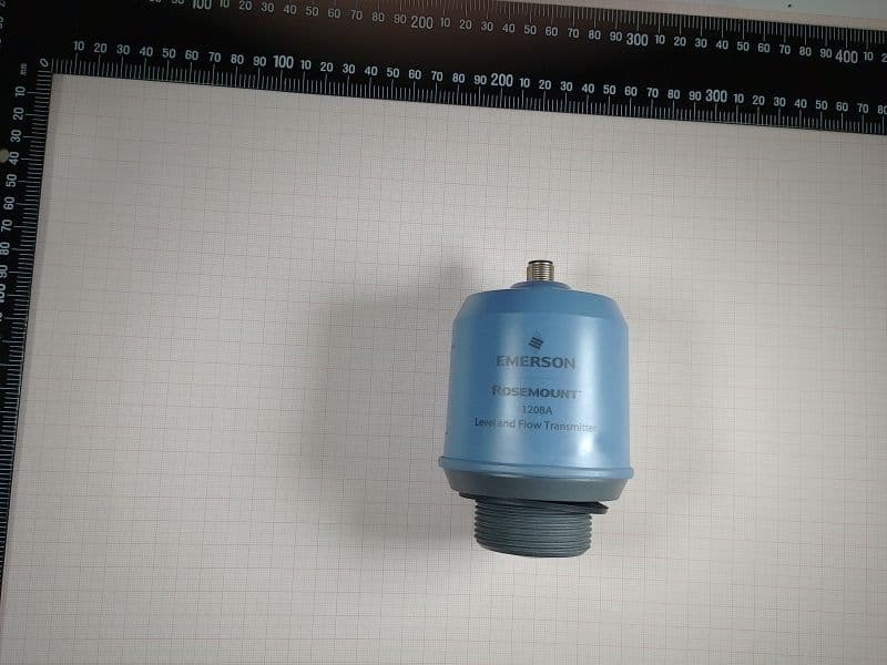
K8C1208LB
Dec 15, 2022Rosemount 1208A Level transmitter
Equipment Class
DTS - Digital Transmission System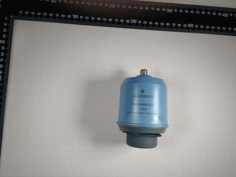
K8C1208L
Dec 15, 2022Rosemount 1208A Level transmitter
Equipment Class
LPR - Level Probing Radar
K8C3408T
Oct 20, 2022Rosemount 3408 Level Transmitter
Equipment Class
LPR - Level Probing Radar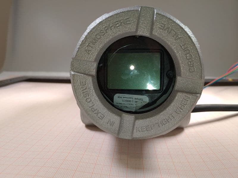
K8C3408TB
Oct 20, 2022Rosemount 3408 Level Transmitter
Equipment Class
LPR - Level Probing Radar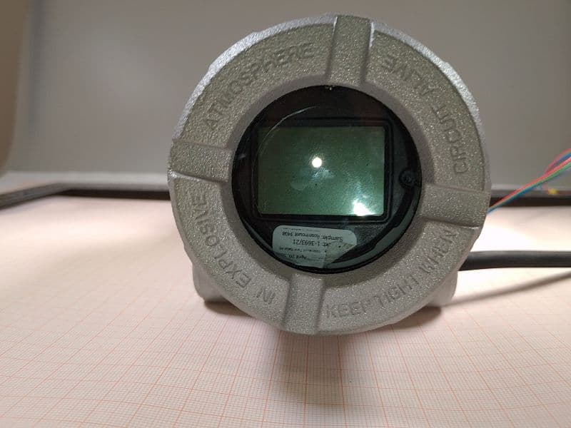
K8C3408LB
Oct 20, 2022Rosemount 3408 Level Transmitter
Equipment Class
DTS - Digital Transmission System