K8C3408LBRosemount 3408 Level Transmitter
Rosemount Tank Radar AB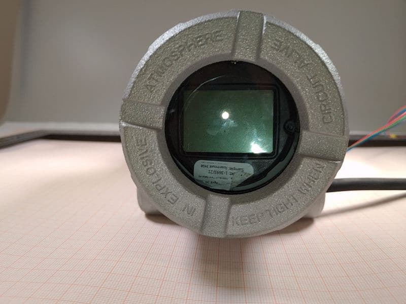
Click to zoom
Application Details
- Equipment Class
- DTS - Digital Transmission System
- Date of Grant
- Oct 20, 2022
- Application Purpose
- Original Equipment
- Date of Application
- Oct 20, 2022
- Equipment Note
- Rosemount 3408 Level Transmitter
- Frequency Range
- 2402.00000000 - 2480.00000000
- Company
- Rosemount Tank Radar AB
- Country
- Sweden
Documents & Files
Document Text
Text extracted from the exhibit documents filed with the FCC. Open a document above to read the original.
Users Manual
Quick Start Guide 00825-0100-4418, Rev AA September 2022 Rosemount ™ 3408 Level Transmitter Non-Contacting Radar Contents About this guide...........................................................................................................................3 Confirm approval type..................................................................................................................5 Mount the process seal antenna...................................................................................................6 Mount the lens antenna............................................................................................................... 8 Mount the ATAP lens antenna.................................................................................................... 10 Rotate the transmitter housing..................................................................................................13 Prepare the electrical connections..............................................................................................14 Connect wiring and power up.....................................................................................................17 Configuration.............................................................................................................................22 Quick Start GuideSeptember 2022 2Emerson.com/Rosemount 1About this guide This Quick Start Guide provides basic guidelines for the Rosemount 3408 Level Transmitter. Refer to the 3408 Reference Manual for more instructions. 1.1Safety messages WARNING Failure to follow safe installation and servicing guidelines could result in death or serious injury. Ensure the transmitter is installed by qualified personnel and in accordance with applicable code of practice. Use the equipment only as specified in this Quick Start Guide and the Reference Manual. Failure to do so may impair the protection provided by the equipment. For installations in hazardous locations, the transmitter must be installed according to the Rosemount 3408 Product Certifications document and System Control Drawing. Repair, e.g. substitution of components, etc. may jeopardize safety and is under no circumstances allowed. WARNING Explosions could result in death or serious injury. Verify that the operating atmosphere of the transmitter is consistent with the appropriate hazardous locations certifications. Before connecting a handheld communicator in an explosive atmosphere, ensure the instruments are installed in accordance with intrinsically safe or non-incendive field wiring practices. In Explosion-proof/Flameproof and Non-Incendive/Type Ex ec installations, do not remove the transmitter cover when power is applied to the unit. The transmitter cover must be fully engaged to meet Explosion-proof/ Flameproof requirements. September 2022Quick Start Guide Quick Start Guide3 WARNING Electrical shock could cause death or serious injury. Ensure the mains power to the transmitter is off and the lines to any other external power source are disconnected or not powered while wiring the transmitter. WARNING Process leaks could result in death or serious injury. Ensure that the transmitter is handled carefully. If the process seal is damaged, gas might escape from the tank. WARNING Physical access Unauthorized personnel may potentially cause significant damage to and/or misconfiguration of end users’ equipment. This could be intentional or unintentional and needs to be protected against. Physical security is an important part of any security program and fundamental to protecting your system. Restrict physical access by unauthorized personnel to protect end users’ assets. This is true for all systems used within the facility. CAUTION Hot surfaces The flange and process seal may be hot at high process temperatures. Allow to cool before servicing. Quick Start GuideSeptember 2022 4Emerson.com/Rosemount 2Confirm approval type For hazardous locations transmitters labeled with multiple approval types: Procedure Permanently mark the checkbox of the selected approval type. Figure 2-1: Label with Multiple Approval Types September 2022Quick Start Guide Quick Start Guide5 3Mount the process seal antenna 3.1Mount the flanged version Procedure 1. Lower the transmitter into the nozzle. Note Be careful not to scratch or otherwise damage the PTFE sealing. Quick Start GuideSeptember 2022 6Emerson.com/Rosemount 2. Tighten the bolts and nuts (see Table 3-1). Note • Re-tighten after 24 hours and again after the first temperature cycle. • Check at regular intervals and re-tighten if necessary. 3.2Torque specifications The conditions used for the calculation are: • Standard mating metal flange • A193 B8M Cl.2 / A4-70 bolt material • Friction coefficient of μ=0.16 Low strength bolt and non-metallic mating flange may require lower tightening torque. Table 3-1: Torque Values for Process Seal Antenna, lb-ft (N-m) Process connection size Process connection rating ASME B16.5EN1092-1JIS B2220 Class 150Class 300PN16PN4010K20K 2-in./DN50/50A29 (40)52 (70)26 (35)29 (40)18 (25)37 (50) 3-in./DN80/80A33 (45)48 (65)37 (50)41 (55)22 (30)70 (95) 4-in./DN100/100A59 (80)52 (70)37 (50)74 (100)26 (35)74 (100) 6-in./DN150/150A66 (90)66 (90)74 (100)136 (185)74 (100)N/A September 2022Quick Start Guide Quick Start Guide7 4Mount the lens antenna 4.1Mount on NPT threaded connections Procedure 1. Apply anti-seize paste or PTFE tape on threads according to your site procedures. 2. Mount the transmitter on the tank. Example • (A) Threaded fitting • (B) Threaded flange A B 46 mm / 50 mm Note Be careful not to scratch or otherwise damage the PTFE sealing. Quick Start GuideSeptember 2022 8Emerson.com/Rosemount 4.2Mount on BSPP (G) threaded connections Procedure 1. Place a suitable gasket on the tank nozzle. Example • (A) Threaded fitting • (B) Threaded flange AB 2. Mount the transmitter on the tank. A B 46 mm / 50 mm Note Be careful not to scratch or otherwise damage the PTFE sealing. S…
Text truncated - open the document above for the full version.
Users Manual
Product Certifications 00880-0100-4418, Rev AA September 2022 Rosemount ™ 3408 Level Transmitter Non-Contacting Radar 1Product certifications Rev 0.20 1.1 European directive and UKCA regulations information A copy of the EU/UKCA Declaration of Conformity can be found at the end of this document. The most recent revision of the EU/UKCA Declaration of Conformity can be found at Emerson.com/Rosemount. 1.2 Safety Instrumented Systems (SIS) SIL 3 Capable: IEC 61508 certified for use in safety instrumented systems up to SIL 3 (Minimum requirement of single use (1oo1) for SIL 2 and redundant use (1oo2) for SIL 3). 1.3 Ordinary location certification As standard, the transmitter has been examined and tested to determine that the design meets the basic electrical, mechanical, and fire protection requirements by a nationally recognized test laboratory (NRTL) as accredited by the Federal Occupational Safety and Health Administration (OSHA). 1.4 Environmental conditions Table 1-1: Environmental Conditions (Ordinary Location and Low Voltage Directive (LVD)) TypeDescription LocationIndoor or outdoor use Maximum altitude6562 ft. (2000 m) Ambient temperature-67 to +185 °F (-55 to +85 °C) Installation categoryDC supplied Electrical supply12-35 Vdc, 1 W Mains supply voltage fluctuationsSafe at 12-35 Vdc ±10% Pollution degree2 1.5 Telecommunication compliance Measurement principle Frequency Modulated Continuous Wave (FMCW), 80 GHz Maximum output power +5 dBm (3.2 mW) Product CertificationsSeptember 2022 2Rosemount 3408 Level Transmitter Frequency range 77.25 to 80.96 GHz LPR (Level Probing Radar) equipment are devices for measurement of level in the open air or in a closed space. Valid for ATAP lens antenna (code SCA). Hardware Version Identification Number (HVIN) is 3408L1 or 3408LB1 (without or with Bluetooth). TLPR (Tank Level Probing Radar) equipment are devices for measurement of level in a closed space only (i.e metallic, concrete or reinforced fiberglass tanks, or similar enclosure structures made of comparable attenuating material). Hardware Version Identification Number (HVIN) is 3408T1 or 3408TB1 (without or with Bluetooth). 1.6 FCC Note: This equipment has been tested and found to comply with the limits for a Class B digital device, pursuant to part 15 of the FCC Rules. These limits are designed to provide reasonable protection against harmful interference in a residential installation. This equipment generates, uses and can radiate radio frequency energy and, if not installed and used in accordance with the instructions, may cause harmful interference to radio communications. However, there is no guarantee that interference will not occur in a particular installation. If this equipment does cause harmful interference to radio or television reception, which can be determined by turning the equipment off and on, the user is encouraged to try to correct the interference by one or more of the following measures: • Reorient or relocate the receiving antenna. • Increase the separation between the equipment and receiver. • Connect the equipment into an outlet on a circuit different from that to which the receiver is connected. • Consult the dealer or an experienced radio/TV technician for help. FCC ID K8C3408L or K8C3408LB (LPR, without or with Bluetooth) K8C3408T or K8C3408TB (TLPR, without or with Bluetooth) 1.7 IC This device complies with Industry Canada’s license-exempt RSS standard. Operation is subject to the following conditions: 1. This device may not cause interference. 2. This device must accept any interference received, including interference that may cause undesired operation. September 2022Product Certifications Product Certifications3 3. The installation of the LPR/TLPR device shall be done by trained installers in strict compliance with the manufacturer’s instructions. 4. The use of this device is on a “no-interference, no-protection” basis. That is, the user shall accept operations of high-powered radar in the same frequency band which may interfere with or damage this device. However, devices found to interfere with primary licensing operations will be required to be removed at the user’s expense. 5. Devices operating under TLPR conditions (i.e. not operating in “Open Air” Mode) shall be installed and operated in a completely enclosed container to prevent RF emissions, which can otherwise interfere with aeronautical navigation. Le présent appareil est conforme aux CNR d'Industrie Canada applicables aux appareils radio exempts de licence. L'exploitation est autorisée aux conditions suivantes: 1. l'appareil ne doit pas produire de brouillage. 2. l'utilisateur de l'appareil doit accepter tout brouillage radioélectrique subi, même si le brouillage est susceptible d'en compromettre le fonctionnement. 3. L’installation d’un dispositif LPR ou TLPR doit être effectuée par des installateurs qualifiés, en pleine conformité avec les instructions du fabricant. 4. Ce dispositif ne peut être exploité qu'en régime de non-brouillage et de non-protection, c'est-à-dire que l'utilisateur doit accepter que des radars de haute puissance de la même bande de fréquences puissent brouiller ce dispositif ou même l'endommager. D'autre part, les capteurs de niveau qui perturbent une exploitation autorisée par licence de fonctionnement principal doivent être enlevés aux frais de leur utilisateur. 5. Un dispositif visé comme TLPR doit être installé et exploité dans un réservoir entièrement fermé afin de prévenir les rayonnements RF qui pourraient autrement perturber la navigation aéronautique. Certificate 2827A-3408L, 2827A-3408LB (LPR, without or with Bluetooth) 2827A-3408T, 2827A-3408TB (TLPR, without or with Bluetooth) 1.8 Radio Equipment Directive (RED) 2014/53/EU and Radio Equipment Regulations S.I. 2017/1206 This device complies with ETSI EN 302 372 (TLPR), ETSI EN 302 729 (LPR), EN 301 489-17 and EN 300 328 (Bluetooth), and EN 62479. Product CertificationsSeptember 2022 4Rosemount 3408 Level Transmitter L…
Text truncated - open the document above for the full version.
Users Manual
Reference Manual 00809-0100-4418, Rev AA September 2022 Rosemount ™ 3408 Level Transmitter Non-Contacting Radar Safety messages NOTICE Read this manual before working with the product. For personal and system safety, and for optimum product performance, ensure you thoroughly understand the contents before installing, using, or maintaining this product. For technical assistance, contacts are listed below: Customer Central Technical support, quoting, and order-related questions. • United States - 1-800-999-9307 (7:00 am to 7:00 pm CST) • Asia Pacific- 65 777 8211 North American Response Center Equipment service needs. • 1-800-654-7768 (24 hours a day — includes Canada) • Outside of these areas, contact your local Emerson representative. WARNING Failure to follow safe installation and servicing guidelines could result in death or serious injury. Ensure the transmitter is installed by qualified personnel and in accordance with applicable code of practice. Use the equipment only as specified in this manual. Failure to do so may impair the protection provided by the equipment. For installations in hazardous locations, the transmitter must be installed according to the Rosemount 3408 Product Certifications document and System Control Drawing. WARNING Explosions could result in death or serious injury. Verify that the operating atmosphere of the transmitter is consistent with the appropriate hazardous locations certifications. Before connecting a handheld communicator in an explosive atmosphere, ensure the instruments are installed in accordance with intrinsically safe or non-incendive field wiring practices. In Explosion-proof/Flameproof and Non-Incendive/Type Ex ec installations, do not remove the transmitter cover when power is applied to the unit. The transmitter cover must be fully engaged to meet Explosion-proof/Flameproof requirements. WARNING Electrical shock could cause death or serious injury. Ensure the mains power to the transmitter is off and the lines to any other external power source are disconnected or not powered while wiring the transmitter. WARNING Process leaks could result in death or serious injury. Ensure that the transmitter is handled carefully. If the process seal is damaged, gas might escape from the tank. 2 WARNING Repair, e.g. substitution of components, etc. may jeopardize safety and is under no circumstances allowed. Unauthorized changes to the product are strictly prohibited as they may unintentionally and unpredictably alter performance and jeopardize safety. Unauthorized changes that interfere with the integrity of the welds or flanges, such as making additional perforations, compromise product integrity and safety. Equipment ratings and certifications are no longer valid on any products that have been damaged or modified without the prior written permission of Emerson. Any continued use of product that has been damaged or modified without the written authorization is at the customer’s sole risk and expense. WARNING Physical access Unauthorized personnel may potentially cause significant damage to and/or misconfiguration of end users’ equipment. This could be intentional or unintentional and needs to be protected against. Physical security is an important part of any security program and fundamental to protecting your system. Restrict physical access by unauthorized personnel to protect end users’ assets. This is true for all systems used within the facility. CAUTION Hot surfaces The flange and process seal may be hot at high process temperatures. Allow to cool before servicing. CAUTION The products described in this document are NOT designed for nuclear-qualified applications. Using non-nuclear qualified products in applications that require nuclear-qualified hardware or products may cause inaccurate readings. For information on Rosemount nuclear-qualified products, contact your local Emerson Sales Representative. 3 4 Contents Chapter 1Introduction.............................................................................................................. 7 1.1 Using this manual........................................................................................................................ 7 1.2 NAMUR NE 53 revision history......................................................................................................7 1.3 Product certifications...................................................................................................................8 1.4 Open source licenses................................................................................................................... 8 1.5 Product recycling/disposal...........................................................................................................8 Chapter 2Transmitter overview.................................................................................................9 2.1 Measurement principle................................................................................................................9 2.2 Process characteristics.................................................................................................................9 2.3 Vessel characteristics.................................................................................................................10 2.4 Non-contacting radar technology..............................................................................................10 2.5 Components of the transmitter.................................................................................................12 2.6 System integration.................................................................................................................... 13 Chapter 3Mechanical installation............................................................................................ 15 3.1 Safety messages........................................................................................................................15 3.2 Con…
Text truncated - open the document above for the full version.
Users Manual
ASpecifications and reference data A.1Performance specifications A.1.1General Reference conditions • Measurement target: Stationary metal plate, no disturbing objects • Antenna: Process seal • Temperature: 59 to 77 °F (15 to 25 °C) • Ambient pressure: 14 to 15 psi (960 to1060 mbar) • Relative humidity: 25-75% • Damping: Default value, 2 s Instrument accuracy (under reference conditions) ±0.04 in. (±1 mm) (1) Repeatability ±0.02 in. (±0.5 mm) Ambient temperature effect ±0.04 in. (±1 mm)/10 K Sensor update rate • Minimum 1 Hz (with 15 Vdc at 4 mA; 12 Vdc at 22.5 mA) • Minimum 0.5 Hz (with 13 Vdc at 4 mA) Maximum level rate 40 mm/s as default, adjustable up to 200 mm/s (1) Refers to inaccuracy according to IEC 60770-1 when excluding installation dependent offset. See the IEC 60770-1 standard for a definition of radar specific performance parameters and if applicable corresponding test procedures. Reference ManualSpecifications and reference data 00809-0100-4418 September 2022 Rosemount 3408 Level Transmitter105 A.1.2Measuring range Table A-1: Maximum Measuring Range, ft. (m) Antenna typeBasic Process Control System (BPCS) Safety Instrumented Systems (SIS) Process seal antenna98 (30)49 (15) Lens antenna49 (15)49 (15) ATAP lens antenna98 (30)49 (15) Note that a combination of adverse process conditions, such as heavy turbulence, foam, and condensation, together with products with poor reflection may affect the measuring range. Accuracy over measuring range Figure A-1 illustrates the accuracy over measuring range at reference conditions. Figure A-1: Accuracy Over Measuring Range B ±0.04 (±1) ±0.20 (±5) 3.9 (100) C A B ±0.04 (±1) ±0.20 (±5) 0.8 (20) 3.9 (100) C A A. Device Reference Point B. Accuracy in inches (millimeters) C. Distance in inches (millimeters) A.1.3Environment Vibration resistance 2 g at 10-1000 Hz according to IEC 61298-3, level “field with general application” Note The bracket option does not meet the vibration requirements. Specifications and reference dataReference Manual September 2022 00809-0100-4418 106Emerson.com/Rosemount Electromagnetic compatibility (EMC) • EMC Directive (2014/30/EU): EN 61326-1 • EN 61326-2-3 • NAMUR recommendations NE21 Pressure Equipment Directive (PED) Complies with 2014/68/EU article 4.3 Built-in lightning protection EN 61326, IEC 61000-4-5, level 2kV Radio approvals • Radio Equipment Directive (2014/53/EU): — ETSI EN 302 372 (TLPR) — ETSI EN 302 729 (LPR) — EN 301 489-17 and EN 300 328 (Bluetooth ® ) — EN 62479 • Part 15 of the FCC Rules • Industry Canada RSS 211 A.2Functional specifications A.2.1General Field of application Continuous level measurements on a broad range of liquids and slurries. Measurement principle Frequency Modulated Continuous Wave (FMCW) Frequency range 77 to 81 GHz Maximum output power +5 dBm (3.2 mW) Internal power consumption < 0.8 W in normal operation Reference ManualSpecifications and reference data 00809-0100-4418 September 2022 Rosemount 3408 Level Transmitter107 Humidity 0 - 100% relative humidity, non-condensing Turn-on time < 60 s (2) A.2.2Functional safety The Rosemount 3408 Level Transmitter is IEC 61508 certified to: • Low and high demand: Type B element • SIL 2 for random integrity @ HFT=0 • SIL 3 for random integrity @ HFT=1 • SIL 3 for systematic capability Related information Functional Safety Certificate Rosemount 3408 Safety Manual A.2.34-20 mA HART Output Two-wire, 4-20 mA. Digital process variable is superimposed on 4-20 mA signal, and available to any host that conforms to the HART protocol. The digital HART ® signal can be used in multidrop mode. HART universal revision 7 Analog signal on alarm The transmitter automatically and continuously performs self-diagnostic routines. If a failure or a measurement error is detected, the analog signal will be driven offscale to alert the user. High or low failure mode is user-configurable. Table A-2: Signal on Alarm StandardHighLow Rosemount standard≥ 21.75 mA≤ 3.75 mA NAMUR NE43≥ 21.0 mA≤ 3.6 mA (2) Time from when power is applied to the transmitter until performance is within specifications. Specifications and reference dataReference Manual September 2022 00809-0100-4418 108Emerson.com/Rosemount Analog saturation levels The transmitter will continue to set a current that corresponds to the measurement until reaching the associated saturation limit (and then freeze). Table A-3: Saturation Levels StandardHighLow Rosemount standard20.8 mA3.9 mA NAMUR NE4320.5 mA3.8 mA A.2.4Bluetooth ® wireless technology Minimum typical range 50 ft. (15 m) line of sight. Maximum communication range will vary depending on orientation, obstacles (person, metal, wall, etc.) or electromagnetic environment. A.2.5Display and configuration Damping User selectable (default is 2 s, minimum is 0 s) Output units • Level and distance: ft., in., m, cm, mm • Level rate: ft/s, in./min, in./s, m/h, m/s • Volume: ft 3 , in. 3 , yd 3 , US gal, imperial gal, barrel (bbl), m 3 , l • Temperature: °F, °C • Signal strength: mV Reference ManualSpecifications and reference data 00809-0100-4418 September 2022 Rosemount 3408 Level Transmitter109 Output variables Variable4-20 mADigital outputLCD display Level✓✓✓ Distance (ullage)✓✓✓ Volume✓✓✓ Scaled variable (1) ✓✓✓ Electronics temperatureN/A✓✓ Signal quality (1) N/A✓✓ Level rateN/A✓✓ Signal strengthN/A✓✓ Percent of rangeN/A✓✓ Percent of range auxiliaryN/A✓✓ User-defined (1) ✓✓✓ Loop currentN/AN/A✓ (1) Only for transmitters ordered with Smart Diagnostics Suite. A.2.6Process pressure Final rating may be lower depending on flange selection. Process seal antenna -15 to 363 psig (-1 to 25 bar) Lens antenna -15 to 363 psig (-1 to 25 bar) ATAP lens antenna -15 to 7 psig (-1 to 0.5 bar) A.2.7Temperature limits Process temperature Process seal antenna -76 to 392 °F (-60 to 200 °C) Lens antenna -76 to 392 °F (-60 to 200 °C) ATAP lens antenna -4 to 176 °F (-20 to 80 °C) Specifications and reference dataReference Manual September 2022 00809-0100-4418 110Emerson.com/R…
Text truncated - open the document above for the full version.
Cover Letter(s)
Document Version 1.1 2020-10-30 LONG-TERM CONFIDENTIALITY REQUEST for Certification Service in the USA Federal Communication Commission Equipment Authorization Division, Application Processing Branch 7435 Oakland Mills Road Columbia, MD 21048 TO WHOM IT M AY CONCERN Pursuant to Paragraphs §0.457 and 0.459 of the Commission’s Rules (47 C.F.R.) and Section §552(b)(4) of the Freedom of Information Act, we request Long-Term Confidentiality for the following product: For the product stated above, we request Long-Term Confidentiality for exhibits which contain Block Diagram, Operational Description, Parts List/Tune Up Info, Schematics, SDR Software/Security Info. The above exhibits contain ou r trade secrets and proprietary information that could be of benefit to o ur competitors. This information will not be publicly available. If you have any questions, please feel free to contact us at the address shown below. Sincerely, Company Name: Phone: Company Address: Fax: E-mail: Contact Name: Signature: Signature Date: Check your GC here. Click Grantee Search. FCC I D: Grantee Code Equipment Product Code
External Photos
Annex C No.1-3693/21-01-01_Annex_C External photos of the Device Under Test This document is electronically signed and valid without handwritten signature. For verification of the electronic signatures, the public keys can be requested at the testing laboratory. Document authorized: Thomas Vogler Lab Manager Radio Communications CTC advanced GmbHUntertuerkheimer Str. 6-10 66117 Saarbruecken / Germany Phone: +49 681 5 98 - 0 Fax: +49 681 5 98 - 9075 web: ctcadvanced.com e-mail: [email protected] Photos Annex A Photo 1 Photo 2 2022-07-14Document 1-3693/21-01-01_Annex_C2/4 Photo 3 Photo 4 2022-07-14Document 1-3693/21-01-01_Annex_C3/4 Photo 5 Photo 6 - END OF DOCUMENT - 2022-07-14Document 1-3693/21-01-01_Annex_C4/4
ID Label/Location Info
MADE IN SWEDEN CERTIFICATE HOLDER: ROSEMOUNT TANK RADAR AB; LAYOUTVÄGEN 1; 435 33 MÖLNLYCKE, SWEDEN LT-01234567801234567801234567 MODEL 3408 A1SHA1I6 1R2AASCA BLE1DA1HR7OAC8AWQ4Q5Q8Q15xxxxxxxxx PXXXX S/N: 22GORK1234567LEVEL TRANSMITTER MFG DATE: 22/06 WARNING/AVERTISSEMENT SUBSTITUTION OF COMPONENTS MAY IMPAIR INTRINSIC SAFETY. POTENTIAL ELECTROSTATIC CHARGING HAZARD. LA SUBSTITUTION DE COMPOSANTS PEUT COMPROMETTRE LA SÉCURITÉ INTRINSÈQUE. RISQUE POTENTIEL DE CHARGE ÉLECTROSTATIQUE. -SEE /-VOIR LES INSTRUCTIONS. INSTALL PER CONTROL DRAWING / INSTALLER SELON LE SCHÉMA DE CONTRÔLE D7000006-887 HART® 4-20 mA 30 VDC 22.5 mA DEVICE REV: XXX PROTOCOL: XXXX HV/SV: 1.0.0/1.0.0(1.A0) FCC ID: K8C3408LB IC: 2827A-3408LB HVIN: 3408LB1 FM21CA0083X INTRINSICALLY SAFE IS CLASS I, II, III DIV 1, GRPS A-G T4...T2 SINGLE SEAL -0.5...52 bar, -60°C...+200°C NI CLASS I, DIV 1, GRPS A-D T4...T2 S CLASS II, III DIV 2, GRPS E-G, T4...T2 CLASS 1 Zone 0 Ex ia IIC T4...T2 Ga CLASS 1 Zone 0/1 Ex ib IIC T4...T2 Ga/Gb Zone 20 Ex ia IIIC T 200 85°C...T 200 250°C Da Zone 20/21 Ex ib IIIC T 200 85°C...T 200 250°C Da/Db (-55°C < Ta < +70°C), TYPE 4X / IP66/67/68
Internal Photos
Annex D No.1-3693/21-01-01_Annex_D Internal photos of the Device Under Test This document is electronically signed and valid without handwritten signature. For verification of the electronic signatures, the public keys can be requested at the testing laboratory. Document authorized: Thomas Vogler Lab Manager Radio Communications CTC advanced GmbHUntertuerkheimer Str. 6-10 66117 Saarbruecken / Germany Phone: +49 681 5 98 - 0 Fax: +49 681 5 98 - 9075 web: ctcadvanced.com e-mail: [email protected] Photos Annex D Photo 1 Photo 2 2022-07-14Document 1-3693/21-01-01_Annex_D2/4 Photo 3 Photo 4 2022-07-14Document 1-3693/21-01-01_Annex_D3/4 Photo 5 - END OF DOCUMENT - 2022-07-14Document 1-3693/21-01-01_Annex_D4/4
RF Exposure Info
SAR Test exemption documentation according to CFR 47 §1.1307 Report identification number: 1-3693/21-03-07 Exemption / MPE (FCC) contains the module with the following certification numbers FCC IDs: K8C3408LB This test report is electronically signed and valid without handwritten signature. For verification of the electronic signatures, the public keys can be requested at the testing laboratory. Document authorised: Alexander Hnatovskiy Marco Scigliano Lab Manager Testing Manager Radio Communications & EMC Radio Communications & EMC Test report no.: 1-3693/21-03-07 © CTC advanced GmbH Page 2 of 3 EUT technologies: Technologies: Max. rated power: (AVG ERP ) Max. gain: Level probing radar 1) 77-81 GHz -35.36 dBm / 0.29μW <0 dBi BT LE 2450 MHz 2) 0.05 dBm (1.01 mW) 0.1 dBi Note: 1) max. measured peak EIRP taken from CTC advanced GmbH report 1-3693/21-01-09 (page 24) (AVG factor -64.38 dB) Max. peak EIRP: 25.33 dBm AVG EIRP: -33.21 dBm, AVG ERP: -35.36 dBm 2) BT LE result taken from CTC advanced GmbH report 1-3693/21-01-10, AVG EIRP: 2.2 dBm, AVG ERP: 0.05dBm Collocation overview: Active scenario: Technology 1 2 3 4 RADAR x x BT LE x x Declared minimum safety distance: 20cm According the manual a safety distance of 20cm shall be applied between the user (and/or bystanders) to the EUT antenna whilst active transmitting. Test report no.: 1-3693/21-03-07 © CTC advanced GmbH Page 3 of 3 MPE-Based Exemption following 47 CFR 1.1307 amendment: If the declared ERP does not exceed the specified threshold based on the calculations below, the device is exempt from routine evaluation. Transmitter Frequency (MHz) Threshold ERP (W) 0.3 – 1.34 1.920 R² 1.34 – 30 3.450 R²/f² 30 – 300 3.83 R² 300 – 1500 0.0128 R² 1500 – 100 000 19.2 R²f where f is the frequency (MHz) R is the separation distance (at least λ/2π) Prediction: worst case (mW) (dBm) LPR 77000 10 0.00029 768.00 28.8 200 EXEMPTED LPR 81000 10 0.00029 768.00 28.8 200 EXEMPTED BT 2450 10 1.01 3060.00 34.8 200 EXEMPTED Treshhold ERP Verdict Technology R min (mm) Transmitter frequency (MHz) Max. decl. ERP (mW) Minimal Safety Distance (mm) Collocation: Overview: Technology , [MHz] LPR BT, 2450 Exemption based on Limit ERP [mW]: 768 3060 Result ERP [mW]: 0.0 1.01 Limit-Exhaustion [%] 0.00004 0.033 Collocated percentage [%] Verdict: …
Text truncated - open the document above for the full version.
Contact Information
Applicant
Dajana Prastalo(E&D, Approvals)
Test Firm
cetecom advanced GmbHGerald Schmidt
Technical Specifications
| # | Rule Parts | Frequency Range | Power Output |
|---|---|---|---|
| 1 | 15C | 2.40 GHz - 2.48 GHz | 1.62 mW |
Other Applications from Rosemount Tank Radar AB
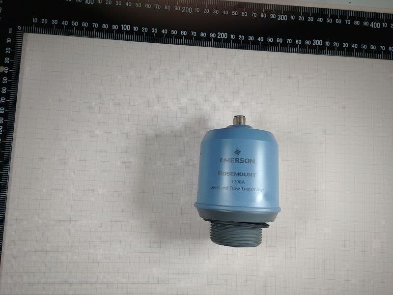
K8C1208CLB
May 09, 2023Level and Flow Transmitter
Equipment Class
LPR - Level Probing Radar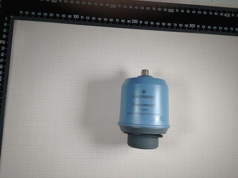
K8C1208LB
Dec 15, 2022Rosemount 1208A Level transmitter
Equipment Class
DTS - Digital Transmission System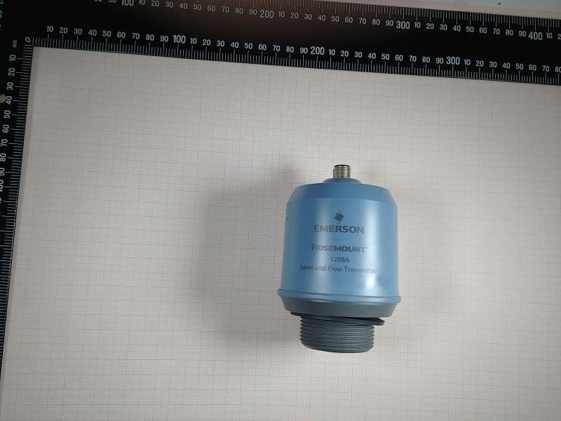
K8C1208L
Dec 15, 2022Rosemount 1208A Level transmitter
Equipment Class
LPR - Level Probing Radar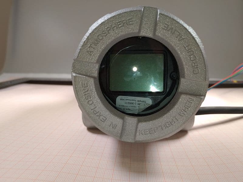
K8C3408T
Oct 20, 2022Rosemount 3408 Level Transmitter
Equipment Class
LPR - Level Probing Radar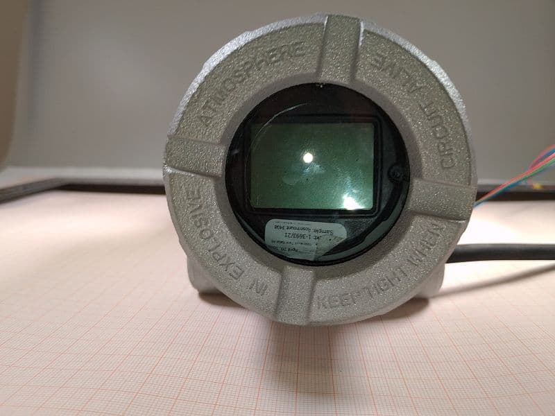
K8C3408TB
Oct 20, 2022Rosemount 3408 Level Transmitter
Equipment Class
LPR - Level Probing Radar