K8C1408LAn LPR in the 77-81 GHz band
Rosemount Tank Radar AB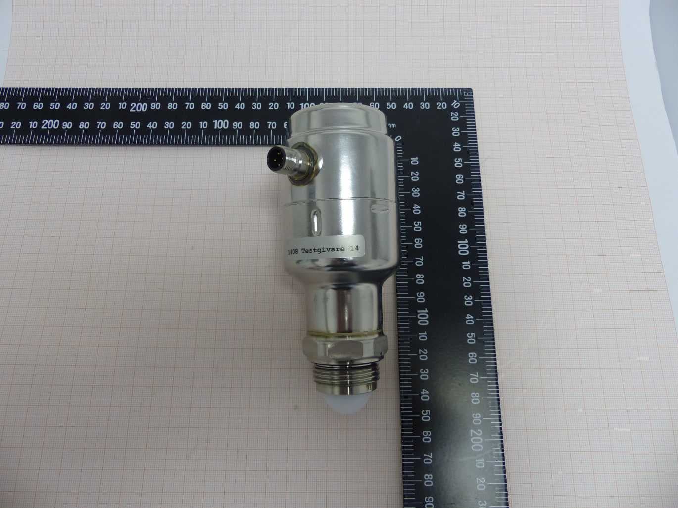
Click to zoom
Application Details
- Equipment Class
- LPR - Level Probing Radar
- Date of Grant
- May 19, 2021
- Application Purpose
- Original Equipment
- Date of Application
- May 19, 2021
- Equipment Note
- An LPR in the 77-81 GHz band
- Frequency Range
- 77000.00000000 - 81000.00000000
- Company
- Rosemount Tank Radar AB
- Country
- Sweden
Documents & Files
Document Text
Text extracted from the exhibit documents filed with the FCC. Open a document above to read the original.
Users Manual
Reference Manual 00809-0200-4480, Rev AA May 2021 Rosemount ™ 1408A Level and Flow Transmitter Non-Contacting Radar Safety messages NOTICE Read this manual before working with the product. For personal and system safety, and for optimum product performance, ensure you thoroughly understand the contents before installing, using, or maintaining this product. For technical assistance, contacts are listed below: Customer Central Technical support, quoting, and order-related questions. • United States - 1-800-999-9307 (7:00 am to 7:00 pm CST) • Asia Pacific- 65 777 8211 North American Response Center Equipment service needs. • 1-800-654-7768 (24 hours a day — includes Canada) • Outside of these areas, contact your local Emerson representative. WARNING Failure to follow safe installation and servicing guidelines could result in death or serious injury. Ensure the transmitter is installed by qualified personnel and in accordance with applicable code of practice. Inspection and maintenance of this equipment shall be carried out by suitably trained personnel, in accordance with the applicable standards and code of practice. Use the equipment only as specified in this manual. Failure to do so may impair the protection provided by the equipment. Repair, e.g. substitution of components, etc. may jeopardize safety and is under no circumstances allowed. WARNING Process leaks could result in death or serious injury. Handle the transmitter carefully. Install and tighten process connectors before applying pressure. Do not attempt to loosen or remove process connectors while the transmitter is in service. WARNING Physical access Unauthorized personnel may potentially cause significant damage to and/or misconfiguration of end users’ equipment. This could be intentional or unintentional and needs to be protected against. Physical security is an important part of any security program and fundamental to protecting your system. Restrict physical access by unauthorized personnel to protect end users’ assets. This is true for all systems used within the facility. CAUTION Hot surfaces The transmitter and process seal may be hot at high process temperatures. Allow to cool before servicing. 2 Contents Chapter 1Introduction.............................................................................................................. 5 1.1 Using this manual........................................................................................................................ 5 1.2 Open source licenses................................................................................................................... 5 1.3 Product recycling/disposal...........................................................................................................5 Chapter 2Transmitter overview.................................................................................................7 2.1 Measurement principle................................................................................................................7 2.2 Process characteristics.................................................................................................................7 2.3 Vessel characteristics...................................................................................................................8 2.4 Application examples...................................................................................................................8 2.5 Components of the transmitter.................................................................................................10 2.6 Easy integration with IO-Link..................................................................................................... 10 Chapter 3Mechanical installation............................................................................................ 13 3.1 Safety messages........................................................................................................................13 3.2 Installation considerations.........................................................................................................13 3.3 Mounting preparations..............................................................................................................18 3.4 Mount transmitter on tank.........................................................................................................19 Chapter 4Electrical installation................................................................................................25 4.1 Safety messages........................................................................................................................25 4.2 Prepare the electrical connections.............................................................................................25 4.3 Power up transmitter.................................................................................................................28 Chapter 5Configuration...........................................................................................................29 5.1 Safety messages........................................................................................................................29 5.2 Overview................................................................................................................................... 29 5.3 Connect the transmitter to the IO-Link...................................................................................... 30 5.4 Get started with your preferred configuration tool.....................................................................30 5.5 Perform the basic setup.............................................................................................................33 Chapter 6Operation and maintenance.....................................................................................35 6.1 Safety messages..........................................................................…
Text truncated - open the document above for the full version.
External Photos
Annex A 1-9604/19-01-01_AnnexA External photos of the Equipment Under Test This addendum is electronically signed and valid without handwritten signature. For verification of the electronic signatures, the public keys can be requested at the testing laboratory. Document authorized: Thomas Vogler Lab Manager Radio Communications & EMC CTC advanced GmbHUntertuerkheimer Str. 6-10 66117 Saarbruecken / Germany Phone: +49 681 5 98 - 0 Fax: +49 681 5 98 - 9075 web: ctcadvanced.com e-mail: [email protected] Photos Photo 1 Photo 2 2020-03-20Document No. 1-9604/19-01-01_AnnexA2/5 Photo 3 Photo 4 2020-03-20Document No. 1-9604/19-01-01_AnnexA3/5 Photo 5 Photo 6 2020-03-20Document No. 1-9604/19-01-01_AnnexA4/5 Document history VersionApplied changesDate of release initial release2020-03-20 - END OF DOCUMENT - 2020-03-20Document No. 1-9604/19-01-01_AnnexA5/5
ID Label/Location Info
Document owner Document type Info class Created Beskrivning/Description I 2020-05-05 Authors Document ID Version Page EAp-TE Terese Ekebrand NCR-Hygienic-DE-0032 1.1 5(6) Stored at J:\NCR-Hygienic\Doc\NCR-Hygienic-DE-0032.docx Rosemount Tank Radar AB Document template: PM Issue 4 Area for marking
Internal Photos
Annex B 1-9604/19-01-01_AnnexB Internal photos of the Equipment Under Test This addendum is electronically signed and valid without handwritten signature. For verification of the electronic signatures, the public keys can be requested at the testing laboratory. Document authorized: Thomas Vogler Lab Manager Radio Communications & EMC CTC advanced GmbHUntertuerkheimer Str. 6-10 66117 Saarbruecken / Germany Phone: +49 681 5 98 - 0 Fax: +49 681 5 98 - 9075 web: ctcadvanced.com e-mail: [email protected] Photos Photo 1 Photo 2 2020-03-20Document No. 1-9604/19-01-01_AnnexB2/8 Photo 3 Photo 4 2020-03-20Document No. 1-9604/19-01-01_AnnexB3/8 Photo 5 Photo 6 2020-03-20Document No. 1-9604/19-01-01_AnnexB4/8 Photo 7 Photo 8 2020-03-20Document No. 1-9604/19-01-01_AnnexB5/8 Photo 9 Photo 10 2020-03-20Document No. 1-9604/19-01-01_AnnexB6/8 Photo 11 2020-03-20Document No. 1-9604/19-01-01_AnnexB7/8 Document history VersionApplied changesDate of release initial release2020-03-20 - END OF DOCUMENT - 2020-03-20Document No. 1-9604/19-01-01_AnnexB8/8
RF Exposure Info
© CTC advanced GmbH Page 1 of 4 BNetzA - CAB - 02/21 - 102 D - P L - 1 2 0 7 6 - 0 1 - 0 3 Maximum Permissible Exposure (MPE) & Exposure evaluation Report identification number: 1-9604/20-01-07_1408L MPE (FCC_ISED) Certification numbers and labeling requirements FCC ID K8C1408L ISED number 2827A-1408L HVIN (Hardware Version Identification Number) 1408L PMN (Product Marketing Name) Rosemount 1408 Level Transmitter FVIN (Firmware Version Identification Number) 1 HMN (Host Marketing Name) -/- This report is electronically signed and valid without handwriting signature. For verification of the electronic signatures, the public keys can be requested at the testing laboratory. Document authorised: Alexander Hnatovskiy Thomas Vogler Lab Manager Lab Manager Radio Communications Radio Communications Report no.: 1-9604/20-01-07_1408L © CTC advanced GmbH Page 2 of 4 EUT technologies: Technologies: Max. power [dBm] conducted EIRP 77-81 GHz Radar n.a. 25.22 dBm Details and origins of the measurements shown in the table above: # Results from: 1-9604/19-01-05 Report no.: 1-9604/20-01-07_1408L © CTC advanced GmbH Page 3 of 4 Prediction of MPE limit at given distance - FCC Equation from page 18 of OET Bulletin 65, Edition 97-01 S = PG / 4π R 2 where: S = Power density P = Power input to the antenna G = Antenna gain R = Distance to the center of radiation of the antenna PG = Output Power including antenna gain The table below is excerpted from Table 1B of 47 CFR 1.1310 titled “Limits for Maximum Permissible Exposure (MPE), Limits for General Population/Uncontrolled Exposure” Frequency Range (MHz) Power Density (mW/cm 2 ) Averaging Time (minutes) 300 -1500 f/1500 30 1500 - 100000 1.0 30 where f = Frequency (MHz) Prediction: worst case TechnologyRadar Frequency79000MHz RDistance20cm PGEIRP25.22dBm SMPE limit for uncontrolled exposure1.0000 mW/cm 2 Calculated Power density:0.0662mW/cm² Calculated percentage of limit:6.62% This prediction demonstrates the following: The power density levels for FCC at a distance of 20 cm are below the maximum levels allowed by regulations. Report no.: 1-9604/20-01-07_1408L © CTC advanced GmbH Page 4 of 4 Prediction of MPE limit at given distance - ISED RSS-102, Issue 5, 2.5.2 RF exposure evaluation is required if the separation distance between the user and/or bystander and the device’s radiating element is greater than 20 cm, except when the device operates as follows: • below 20 MHz and the source-based, time-averaged maximum e.i.r.p. of the device is equal to or less than 1 W (adjusted for tune-up tolerance); • at or above 20 MHz and below 48 MHz and the source-based, time-averaged maximum e.i.r.p. of the device is equal to or less than 4.49/ƒ 0.5 W (adjusted for tune-up tolerance), where ƒ is in MHz; • at or above 48 MHz and below 300 MHz and the source-based, time-averaged maximum e.i.r.p. of the device is equal to or less than 0.6 W (adjusted for tune-up tolerance); • at or above 300 MHz and below 6 GHz and the source-based, time-averaged maximum e.i.r.p. of the device is equal to or less than 1.31 x 10 -2 ƒ 0.6834 W (adjusted for tune-up tolerance), where ƒ is in MHz; • at or above 6 GHz and the source-based, time-averaged maximum e.i.r.p. of the device is equal to or less than 5 W (adjusted for tune-up tolerance). Prediction: worst case 77 - 81 GHz Frequency 79000 MHz R Distance 20 cm P G Maximum EIRP 25.22 dBm P G Maximum EIRP 332.7 mW Exclusion Limit from above: 5.00 W Calculated percentage of Limit: 6.65% Conclusion: RF exposure evaluation is not required.
Test Report
BNetzA - CAB - 02/21 - 102 TEST REPORT Test report no.: 1-9604/19-01-05-A Testing laboratory Applicant CTC advanced GmbH Untertuerkheimer Strasse 6 – 10 66117 Saarbruecken / Germany Phone: + 49 681 5 98 - 0 Fax: + 49 681 5 98 - 9075 Internet: http://www.ctcadvanced.com e-mail: [email protected] Accredited Testing Laboratory: The testing laboratory (area of testing) is accredited according to DIN EN ISO/IEC 17025 (2005) by the Deutsche Akkreditierungsstelle GmbH (DAkkS) The accreditation is valid for the scope of testing procedures as stated in the accreditation certificate starting with the registration number: D-PL-12076-01. Rosemount Tank Radar AB Layoutvägen 1 P O Box 150 435 33 Mölnlycke / SWEDEN Phone: +46 31 3370 0000 Contact: Terese Ekebrand e-mail: [email protected] Phone: -/- Manufacturer Rosemount Tank Radar AB P O Box 150 Layoutvägen 1 435 33 Mölnlycke / SWEDEN Test standard/s 47 CFR Part 15 Title 47 of the Code of Federal Regulations; Chapter I; Part 15 – Radio frequency devices RSS-211 Level Probing Radar Equipment For further applied test standards please refer to section 3 of this test report. Test Item Kind of test item: 77-81 GHz level probing radar Model name: Rosemount 1408 Level Transmitter FCC ID: K8C1408L IC: 2827A-1408L Frequency: 77 – 81 GHz Technology tested: FMCW radar Antenna: Lens antenna Power supply: 24 V (min. 18 to max. 30 V DC) Temperature range: -40° to +80° This test report is electronically signed and valid without handwritten signature. For verification of the electronic signatures, the public keys can be requested at the testing laboratory. Test report authorized: Test performed: p.o. Karsten Geraldy Thomas Vogler Lab Manager Lab Manager Radio Communications Radio Communications Test report no.: 1-9604/19-01-05-A © CTC advanced GmbH Page 2 of 33 1 Table of contents 1 Table of contents ............................................................................................................................................. 2 2 General information ......................................................................................................................................... 3 2.1 Notes and disclaimer ........................................................................................................................... 3 2.2 Application details ............................................................................................................................... 3 2.3 Test laboratories sub-contracted ........................................................................................................ 3 3 Test standard/s, references and accreditations .............................................................................................. 4 4 Test environment ............................................................................................................................................. 5 5 Test item .......................................................................................................................................................... 5 5.1 General description ............................................................................................................................. 5 5.2 Additional information ........................................................................................................................ 5 6 Sequence of testing ....................................................................................................................................... 6 6.1 Sequence of testing radiated spurious 9 kHz to 30 MHz ............................................................... 6 6.2 Sequence of testing radiated spurious 30 MHz to 1 GHz .............................................................. 7 6.3 Sequence of testing radiated spurious 1 GHz to 18 GHz .............................................................. 8 6.4 Sequence of testing radiated spurious above 18 GHz .................................................................. 9 6.5 Sequence of testing radiated spurious above 50 GHz with external mixers ............................. 10 7 Description of the test setup ....................................................................................................................... 11 7.1 Shielded semi anechoic chamber .................................................................................................. 12 7.2 Radiated measurements fully anechoic chamber ........................................................................ 13 7.3 Radiated measurements 18 GHz to 50 GHz in test lab ................................................................ 14 7.4 Radiated measurements > 50 GHz in test lab ............................................................................... 14 8 Measurement uncertainty ............................................................................................................................ 15 9 Summary of measurement results ............................................................................................................. 16 10 Summary of measurement results ......................................................................................................... 17 10.1 Frequency stability and fundamental bandwidth ......................................................................... 17 10.2 Fundamental emissions .................................................................................................................. 19 10.3 Unwanted emissions limit ............................................................................................................... 22 10.4 Antenna beamwidth and antenna side lobe gain ......................................................................... 29 10.5 Emissions from digital circuitry ..................................................................................................... 30 11 Glossary.......................…
Text truncated - open the document above for the full version.
Test Setup Photos
Annex F 1-9604/19-01-01_AnnexF Setup photos of the Equipment Under Test (LPR) This addendum is electronically signed and valid without handwritten signature. For verification of the electronic signatures, the public keys can be requested at the testing laboratory. Document authorized: Thomas Vogler Lab Manager Radio Communications & EMC CTC advanced GmbHUntertuerkheimer Str. 6-10 66117 Saarbruecken / Germany Phone: +49 681 5 98 - 0 Fax: +49 681 5 98 - 9075 web: ctcadvanced.com e-mail: [email protected] Photos Photo 1 Photo 2 2020-03-20Document No. 1-9604/19-01-01_AnnexF2/4 Photo 3 Photo 4 2020-03-20Document No. 1-9604/19-01-01_AnnexF3/4 Document history VersionApplied changesDate of release initial release2020-03-20 - END OF DOCUMENT - 2020-03-20Document No. 1-9604/19-01-01_AnnexF4/4
Contact Information
Applicant
Dajana Prastalo(E&D, Approvals)
Test Firm
cetecom advanced GmbHGerald Schmidt
Technical Specifications
| # | Rule Parts | Frequency Range | Power Output |
|---|---|---|---|
| 1 | 15.256 | 77.00 GHz - 81.00 GHz | 333.00 mW |
Other Applications from Rosemount Tank Radar AB
K8C1208CLB
May 09, 2023Level and Flow Transmitter
Equipment Class
LPR - Level Probing Radar
K8C1208LB
Dec 15, 2022Rosemount 1208A Level transmitter
Equipment Class
DTS - Digital Transmission System
K8C1208L
Dec 15, 2022Rosemount 1208A Level transmitter
Equipment Class
LPR - Level Probing Radar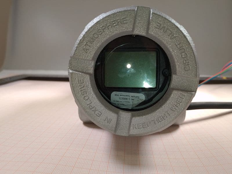
K8C3408T
Oct 20, 2022Rosemount 3408 Level Transmitter
Equipment Class
LPR - Level Probing Radar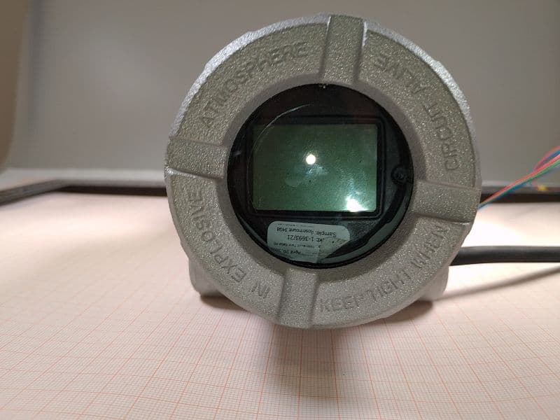
K8C3408TB
Oct 20, 2022Rosemount 3408 Level Transmitter
Equipment Class
LPR - Level Probing Radar