K8C5401Radar Level Gauge
Rosemount Tank Radar AB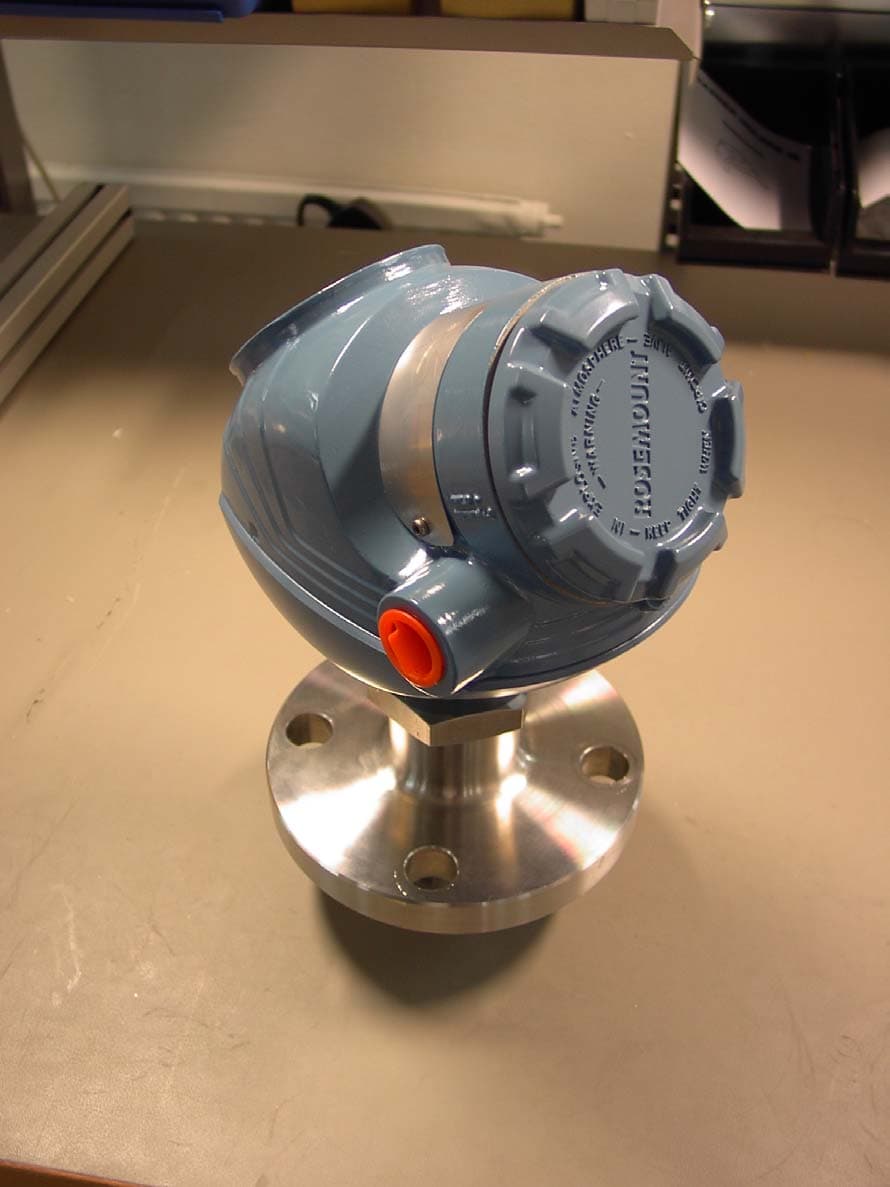
Click to zoom
Application Details
- Equipment Class
- DXX - Part 15 Low Power Communication Device Transmitter
- Date of Grant
- Jan 11, 2004
- Application Purpose
- Original Equipment
- Date of Application
- Nov 24, 2003
- Equipment Note
- Radar Level Gauge
- Frequency Range
- 6300.00000000 - 6300.00000000
- Company
- Rosemount Tank Radar AB
- Country
- Sweden
Documents & Files
Document Text
Text extracted from the exhibit documents filed with the FCC. Open a document above to read the original.
Users Manual
www.rosemount.com Reference Manual 00809-0100-4026, Rev AA November 2003 Preliminary copy Rosemount 5400 Series Subtitle Reference Manual 00809-0100-4026, Rev AA November 2003 Rosemount 5400 Series www.rosemount.com Preliminary copy Rosemount 5400 Series Rosemount 5400 Series Radar Transmitter may be protected by one or more U.S. Patents pending and foreign patents pending. Rosemount and the Rosemount logotype are registered trademarks of Rosemount Inc. HART is a registered trademark of the HART Communication Foundation. Teflon, VITON, and Kalrez are registered trademarks of E.I. du Pont de Nemours & Co. Asset Management Solutions is a trademark of Emerson Process Management. Cover Photo: xx NOTICE Read this manual before working with the product. For personal and system safety, and for optimum product performance, make sure you thoroughly understand the contents before installing, using, or maintaining this product. Within the United States, Rosemount Inc. has two toll-free assistance numbers. Customer Central: 1-800-999-9307(7:00 a.m. to 7:00 p.m. CST) Technical support, quoting, and order-related questions. North American Response Center: Equipment service needs. 1-800-654-7768 (24 hours a day ñ Includes Canada) For equipment service or support needs outside the United States, contact your local Rosemount representative. The products described in this document are NOT designed for nuclear-qualified applications. Using non-nuclear qualified products in applications that require nuclear-qualified hardware or products may cause inaccurate readings. For information on Rosemount nuclear-qualified products, contact your local Rosemount Sales Representative. This product is designed to meet FCC and R&TTE requirements for a non-intentional radiator. This device complies with part 15 of the FCC rules. Operation is subject to the following two conditions: (1) This device may not cause harmful interference, and (2) this device must accept any interference received, including interference that may cause undesired operation. Reference Manual 00809-0100-4026, Rev AA November 2003 Rosemount 5400 Series www.rosemount.com Table of Contents SECTION 1 Introduction Safety Messages . . . . . . . . . . . . . . . . . . . . . . . . . . . . . . . . . . . . . . . . . 1-1 Manual Overview . . . . . . . . . . . . . . . . . . . . . . . . . . . . . . . . . . . . . . . . . 1-2 SECTION 2 Transmitter Overview Theory of Operation. . . . . . . . . . . . . . . . . . . . . . . . . . . . . . . . . . . . . . . 2-1 Components of the transmitter . . . . . . . . . . . . . . . . . . . . . . . . . . . . . . 2-2 System Architecture. . . . . . . . . . . . . . . . . . . . . . . . . . . . . . . . . . . . . . . 2-3 Process Characteristics . . . . . . . . . . . . . . . . . . . . . . . . . . . . . . . . . . . . 2-4 Dielectric constant . . . . . . . . . . . . . . . . . . . . . . . . . . . . . . . . . . . . . 2-4 Foam . . . . . . . . . . . . . . . . . . . . . . . . . . . . . . . . . . . . . . . . . . . . . . . 2-4 Turbulence . . . . . . . . . . . . . . . . . . . . . . . . . . . . . . . . . . . . . . . . . . . 2-4 Temperature/Pressure . . . . . . . . . . . . . . . . . . . . . . . . . . . . . . . . . . 2-4 Vapor . . . . . . . . . . . . . . . . . . . . . . . . . . . . . . . . . . . . . . . . . . . . . . . 2-4 Condensation . . . . . . . . . . . . . . . . . . . . . . . . . . . . . . . . . . . . . . . . . 2-4 Tank Characteristics . . . . . . . . . . . . . . . . . . . . . . . . . . . . . . . . . . . . 2-4 Antenna Selection Guide/Measuring Range . . . . . . . . . . . . . . . . . . . . 2-5 SECTION 3 Installation Safety messages . . . . . . . . . . . . . . . . . . . . . . . . . . . . . . . . . . . . . . . . . 3-1 Installation Procedure . . . . . . . . . . . . . . . . . . . . . . . . . . . . . . . . . . . . . 3-2 Mounting Considerations . . . . . . . . . . . . . . . . . . . . . . . . . . . . . . . . . . . 3-3 Socket Requirements . . . . . . . . . . . . . . . . . . . . . . . . . . . . . . . . . . . 3-3 Free Space . . . . . . . . . . . . . . . . . . . . . . . . . . . . . . . . . . . . . . . . . . . 3-4 Recommended Mounting Position . . . . . . . . . . . . . . . . . . . . . . . . . 3-5 Beam Width . . . . . . . . . . . . . . . . . . . . . . . . . . . . . . . . . . . . . . . . . . 3-6 Beam Diameter at different distances from flange for 5401 . . . 3-6 Beam Diameter at different distances from flange for 5402 . . . 3-6 Beam angle for 5401 . . . . . . . . . . . . . . . . . . . . . . . . . . . . . . . . . 3-7 Beam angle for 5402 . . . . . . . . . . . . . . . . . . . . . . . . . . . . . . . . . 3-7 Vessel Characteristics . . . . . . . . . . . . . . . . . . . . . . . . . . . . . . . . . . 3-8 Disturbing objects . . . . . . . . . . . . . . . . . . . . . . . . . . . . . . . . . . . . . . 3-8 Mechanical Installation . . . . . . . . . . . . . . . . . . . . . . . . . . . . . . . . . . . . 3-9 Mounting a standard cone antenna . . . . . . . . . . . . . . . . . . . . . . . . 3-9 Mounting in Still Pipes . . . . . . . . . . . . . . . . . . . . . . . . . . . . . . . . . 3-10 Mounting in Bypass Pipes . . . . . . . . . . . . . . . . . . . . . . . . . . . . . . 3-11 Antenna extension . . . . . . . . . . . . . . . . . . . . . . . . . . . . . . . . . . . . 3-12 ìDisc Antennaî . . . . . . . . . . . . . . . . . . . . . . . . . . . . . . . . . . . . . . . 3-12 Electrical Installation . . . . . . . . . . . . . . . . . . . . . . . . . . . . . . . . . . . . . 3-13 Cable/conduit entries . . . . . . . . . . . . . . . . . . . . . . . . . . . . . . . . . . 3-13 Grounding. . . . . . . . . . . . . . . . . . . . . . . . . . . . . . . . . . . . . . . . . . . 3-13 Cable Selection . . . . . . . . . . . . . . . . . . . . . . . . . . . . . . . . . . . . . . 3-13 Hazardous Areas . . . . . . . . . . . . . . . . . . . . . . . . . . . . . . . . . . . . . 3-13 Power Requirements . . . . . . . . . . . . . . . . . . . . . . . . . . . . . . . . . . 3-14 Maximum Loop Resistance . . . . . . . . . . . …
Text truncated - open the document above for the full version.
Cover Letter(s)
Request for confidentiality Saab Tank Control respectfully requests that in accordance with §§ 0.457 (d), 0.459 confidentiality be provided for all detailed technical information, for the schematics, and for the block diagrams contained within this application. In support of this request, we show the following. Enclosed within our application is technical information, which we deem to be trade secrets and proprietary. If made public, the information might be used to our disadvantage in the marketplace. The equipment covered in this application is a Radar Level Gauge designed for measurement in closed metallic tanks under Part 15 as well as under open conditions under Part 90, in the later case with a site-license. Saab Tank Control is one of the world’s largest producers of level gauges and has sold and installed more than 30,000 gauges worldwide. Saab Tank Control requires that all installations of the above-captioned device be performed by Saab Tank Control’s personnel, who are the sole source of maintenance for the gauges. Additionally, Saab Tank Control maintains records on the sale and installation of all such gauges worldwide. To assist in assuring that we receive the full value of our license and protect our competitive posture, we respectfully request grant of confidentiality for all information mentioned above. We feel that a grant of confidentiality is only proper as our gauges only enters the stream of commerce under strict control of our employees. The gauge will consequently not be subject to the examination of our competitors. For the above stated reasons, Saab Tank Control hereby requests that our application be processed to grant in accord with the Commission’s Rules and the stated intention of the Bureau in creation of those same Rules. Gothenburg 2003-11-18 Carl Fjelkner, Product Manager
ID Label/Location Info
All text except, FCC information, Model name, Rosemount logo and manufacturing country/city is example text. The label above is placed as in the “External Photos” document. GÖTEBORG, SWEDEN RADAR LEVEL TRANSMITTER 5401______________________ S/N_____________________ MFG_____________________ MAY BE PROTECTED BY US AND FOREIGN PATENTS AND PATENTS PENDING SUPPLY: 10,5 – 30VDC (I.S.) FCC ID: K8C5401 ENCL. TYPE 4X, IP66, IP67 IS CL I, II, III, DIV. 1, GP A,B,C,D,E,F & G CL I, ZONE 0, AEx ia IIC T4 WHEN INSTALLED PER CONTROL DWG 9150077-XXX NI CL I, DIV 2, GP A,B,C & D; SUITABLE FOR CL II, III DIV 2, GP F & G; NI MAX 42,5 V, 25mA AMBIENT TEMPERATURE LIMITS -40 o C to +70 o C WARNING: SUBSTITUTION OF COMPONENTS MAY IMPAIR SUITABILITY FOR DIV 1 & WARNING: EXPLOSION HAZARD – DO NOT DISCONNECT EQUIPMENT UNLESS AREA IS KNOWN TO BE NON-HAZARDOUS I5/HART TAG_____________________
Internal Photos
1. Assembly 1 2. Assembly 2 3. PMM Front 4. PMM Back 5. Assembly 3 See “Internal Photos 2” for more photos
Internal Photos
1. MB Front 2. MB Back 3. Assembly 4 4. IBH Front 5. IBH Back See “internal photos 3” for more information
Internal Photos
1. Display 2. Assembly 5 3. Assembly 6 4. EB Front 5. EB Back See “Internal Photos 4” for more photos
Internal Photos
1. EB w plate front 2. EB w plate back 3. Assembly 7 19. Assembly 8
Test Report
1 Page: 1 of 7 TEST REF. NO: 03/2062A DATE: October 21, 2003 TEST REPORT REPORT CERTIFICATE issued by a FCC listed Test Laboratory CUSTOMER Project No: 03210 Saab Marine Electronics AB Låsblecksgatan 9 SE-589 41 Linköping Sweden MANUFACTURER: Saab Rosemount Sweden EQUIPMENT UNDER TEST (EUT): Radar Level Gauge. Model: Rosemount 5401. Prototype No: P3 14. TEST SPEC.: 47 Cfr Ch. 1 (10-1-01 Edition): 1. Part 15, Subpart B, Class B, Digital Devices. 1.1. § 15.107. Conducted emission 1.2. § 15.109. Radiated emission 2. Part 15, Subpart C, Field Disturbance Sensor. 2.1. § 15.207. Conducted emission 2.2. § 15.209. Radiated emission DATE OF TEST: September 29 - 31, 2003 TEST SITE: Svenska EMC Lab AB, Karlskrona, Sweden. FCC registration number: 90967. SWEDAC accreditation number: 1713 TEST RESULT: The EUT (Equipment Under Test) did pass the above mentioned test. ------------------------------------------------------------------------------------------------------------------------ Approved, Karlskrona October 21, 2003 ............................................ Hans Östergren Manager Svenska EMC Lab AB This Test Report shall not be reproduced, except in full, without the written approval of Svenska EMC Lab AB 2 Page: 2 of 7 TEST REF. NO: 03/2062A DATE: October 21, 2003 _________________________________________________________________________________ DATE OF RECEIPT: September 29, 2003 CONDITION OF EUT: No remarks. Operates as intended. TEST PERSONNEL: Svenska EMC Lab AB: Bo Gidlöw. ASSISTANT PERSONNEL: Saab Marine Electronics AB: Mikael Kleman. DESCRIPTION OF THE EUT: The EUT is a Radar Tank Gauge used in industrial environments. The radar frequency is 6.3 GHz. The output power is below 1 mW. To control the radar digital circuits are integrated in the same enclosure as the radar transmitter-receiver. A display and switches for the operation is built-in. Three different types of antennas were delivered together with the EUT: 1. Horn Antenna, 8” 2. Horn Antenna, 6” 3. Horn Antenna, 4” The radar is designed for installation in different types of tanks or to operate in open environment. The test sample was measured with tanks of different materials and also measured without any additional tank. The EUT input power range is 18 – 36 VDC. Output signal is 4 – 20 mA in the power cable. This signal could be detected with a simple passive peripheral unit. CALIBRATION DECLARATION: The test equipment is calibrated as the calibration information in the Test Equipment list. Before starting of the tests the check points in the applicable Checklists were confirmed. ESTIMATED UNCERTAINTY: Expanded uncertainty (k = 2), Conducted Emission, 0.45 – 30 MHz: ± 1.2 dB Expanded uncertainty (k = 2), Field Strength, emission 9 kHz – 1000 MHz: ± 2.4 dB Expanded uncertainty (k = 2), Field Strength, emission 1 to 40 GHz: ± 3 dB Frequency, 0.45 – 1000 MHz: ± 10 Hz Frequency, 1 – 40 GHz: ± 100 kHz The uncertainties are for a confidence level of not less than 95 %. 3 Page: 3 of 7 TEST REF. NO: 03/2062A DATE: October 21, 2003 _________________________________________________________________________________ TEST EQUIPMENT: Type/Manufacturer/Bandwidth s/n Calibration information Date Interval For emission test up to 1 GHz: EMI Test System, Monitor EZM, 860157/014 0308 12 months Rohde & Schwarz EP-6, 20 Hz - 1300 MHz Test Receiver, Rohde & Schwarz ESH-3, 894979/013 0308 12 months 9 kHz - 30 MHz Test Receiver, Rohde & Schwarz ESVP, 893497/006 0308 12 months 20 - 1300 MHz Pulse Limiter Rohde & Schwarz ESH3-Z2 357881052 0308 12 months DC - 30 MHz Plotter, Rohde & Schwarz DOP 2 893117/0008 0308 12 months LISN 50 OHM/50 μH, Schwarzbeck 93-84105 0308 12 months NSLK8126, 10 kHz - 30 MHz, 25 A Software, Rohde & Schwarz EZM K-1 K 1 V 1.06 0308 12 months Biconical Antenna, Schwarzbeck BBA9106 93-92196.1 0308 12 months 30 - 300 MHz Log-periodic Antenna, Schwarzbeck UHALP9107, 91071205 0308 12 months 300 - 1000 MHz Coaxial cable, Suhner RG214 93-1217 0309 12 months Antenna Mast System, Jyske EMC, h = 1 - 4 m 93-90172 NA NA Turn Table, Jyske EMC 93-90171 NA NA Shielded Chamber, Jyske EMC, 11 x 6 x 4.5 m 93-90168 0303 36 months Anechoic Chamber, 8 x 4.5 x 3 m 93-87151 0304 36 months Open Area Test Site for 3 m antenna distance - 0304 36 months For emission test at fundamental frequency 6.3 GHz and for emission test 1 to 18 GHz: Spectrum Analyzer, HP 8566B 2950A06284 0003 12 months Plotter, HP 7475A 2641L16543 NA NA Signal Amplifier, HP 8449B, 1 – 26.5 GHz 3008A00514 0306 12 months Double Ridged Guide Antenna, EMCO 3115, 2338 0308 36 months 1 - 18 GHz Coaxial Cable, Sucoflex 104, l = 5 m 171288/4 0309 12 months Coaxial Cable, Sucoflex 104, l = 0.5 m 180067/4 0309 12 months For emission test at harmonic frequencies above 18 GHz: Spectrum Analyzer, HP 8566B 2950A06284 0309 12 months Plotter, HP 7475A 2641L16543 NA NA Signal Mixer, HP 11970K, 18 - 26.5 GHz UA-004 0105 36 months Signal Mixer, HP 11970A, 26.5 - 40 GHz UA-005 0105 36 months Mixer Amplifier, HP 11975A, 2 - 8 GHz FO-003 0105 36 months Standard Gain Horn Antenna, Microguide AT-001 0003 36 months AN180-DR, 18 - 40 GHz. Adapter coaxial to waveguide, Sealectro DA-001 0003 36 months 18 – 40 GHz 4 Page: 4 of 7 TEST REF. NO: 03/2062A DATE: October 21, 2003 _________________________________________________________________________________ TEST SET-UP AND PROCEDURE: See Appendix 1 to 3. As laid out in ANSI C.63.4:1992 Document. Tested as table top equipment. Radiated emission test: Over-head cable. The signal cables were fixed on a wooden stand of 2.3 m in height and 1.5 m in width. TEST CONDITIONS: Rating: 115 VAC, 60 Hz, to the peripheral Power Supply. 24 VDC 22 mA to the Tank Radar. Peripherals: AC/DC Power Supply, Trio PR-630, 115 VAC / 24 VDC. Class I. Modem HART. 250 Ω resistor. Current Meter. PC for configuration of the system. Cables: Unshielded combined power line and signal cable of 15 m length without protective earth. Unshielded mains cable of 2.5 m length to the Power Supply. Configur…
Text truncated - open the document above for the full version.
Contact Information
Applicant
Dajana Prastalo(E&D, Approvals)
Technical Contact
Saab Marine Electronics ABCarl O Fjelkner
[email protected]+46-31-3370280
Gamlestadsv�gen 18B · Gothenburg · Sweden
Non-Technical Contact
Saab Marine Electronics ABCarl O Fjelkner
[email protected]+46-31-3370280
Test Firm
Svenska EMC Lab ABHans Ostergren
Technical Specifications
| # | Rule Parts | Frequency Range | Power Output |
|---|---|---|---|
| 1 | 15C | 6.30 GHz - 6.30 GHz | - |
Other Applications from Rosemount Tank Radar AB
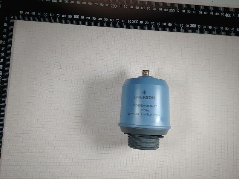
K8C1208CLB
May 09, 2023Level and Flow Transmitter
Equipment Class
LPR - Level Probing Radar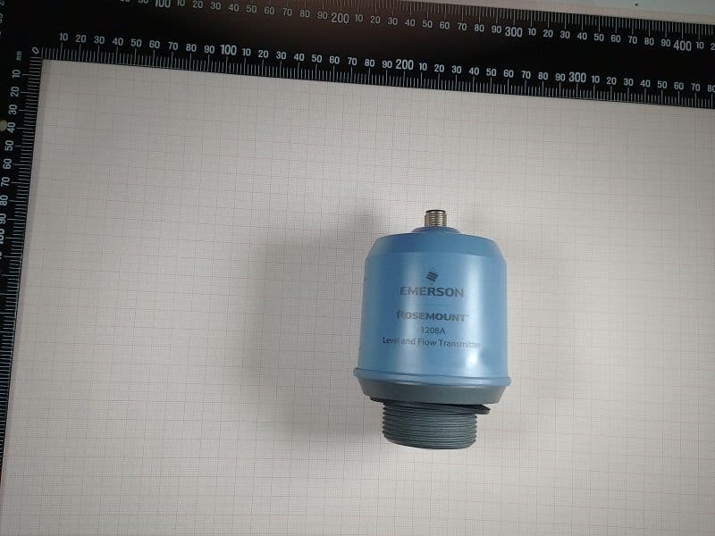
K8C1208LB
Dec 15, 2022Rosemount 1208A Level transmitter
Equipment Class
DTS - Digital Transmission System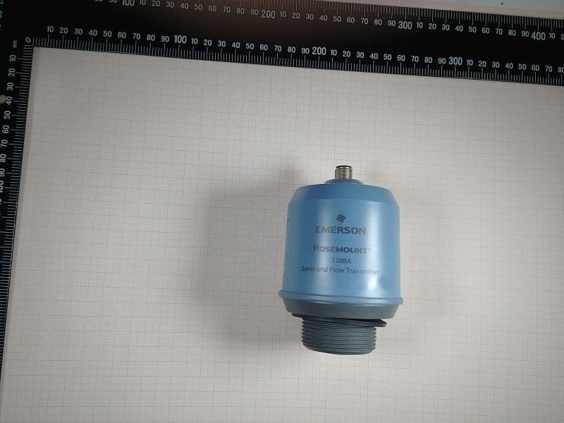
K8C1208L
Dec 15, 2022Rosemount 1208A Level transmitter
Equipment Class
LPR - Level Probing Radar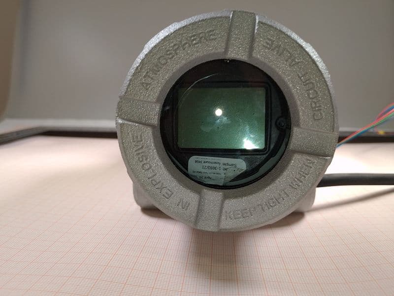
K8C3408T
Oct 20, 2022Rosemount 3408 Level Transmitter
Equipment Class
LPR - Level Probing Radar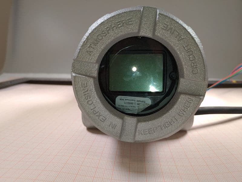
K8C3408TB
Oct 20, 2022Rosemount 3408 Level Transmitter
Equipment Class
LPR - Level Probing Radar