K8C5900Rosemount 5900S Radar Level Gauge
Rosemount Tank Radar AB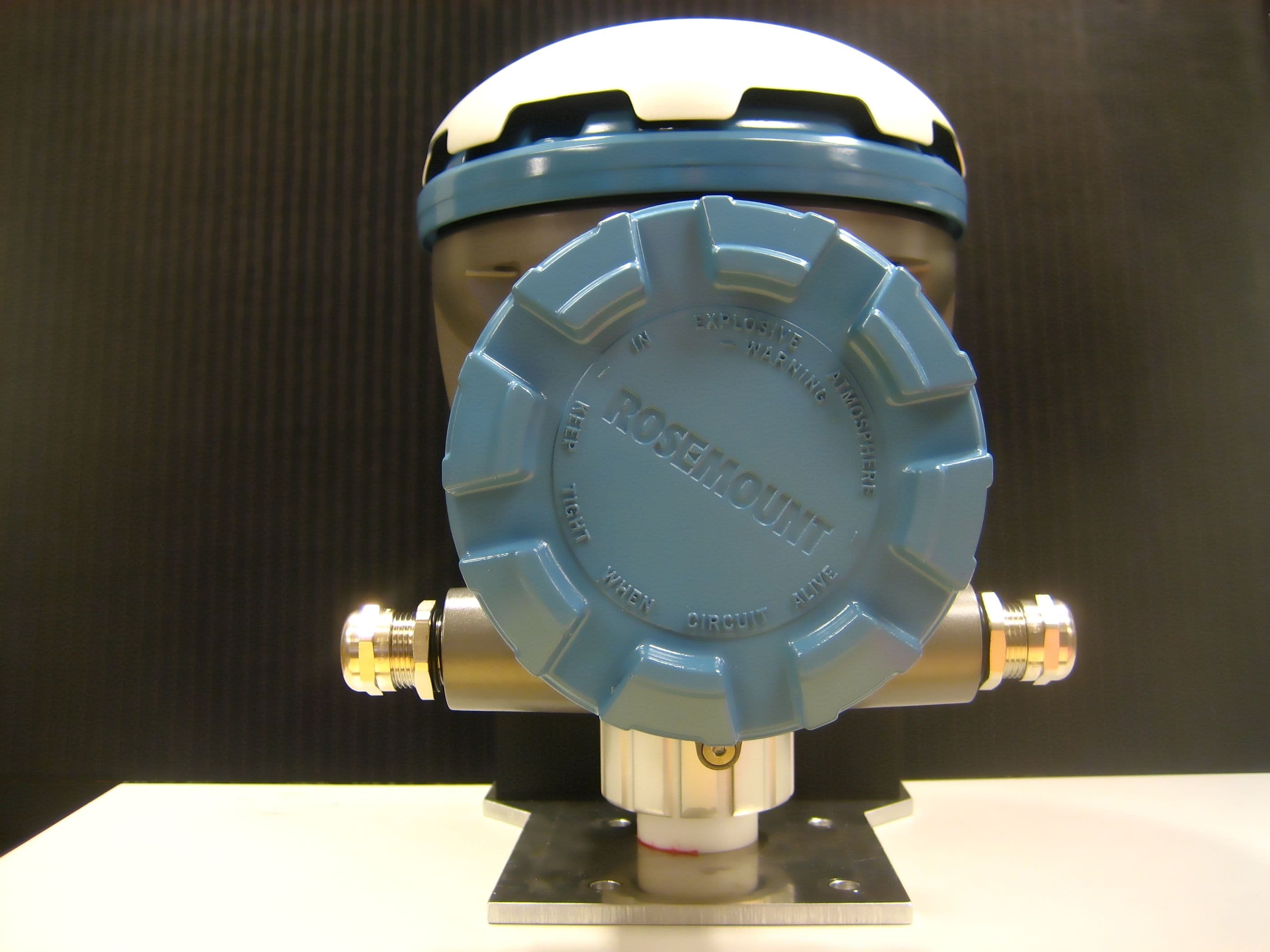
Click to zoom
Application Details
- Equipment Class
- DXT - Part 15 Low Power Transceiver, Rx Verified
- Date of Grant
- Jan 06, 2010
- Application Purpose
- Original Equipment
- Date of Application
- Nov 29, 2009
- Equipment Note
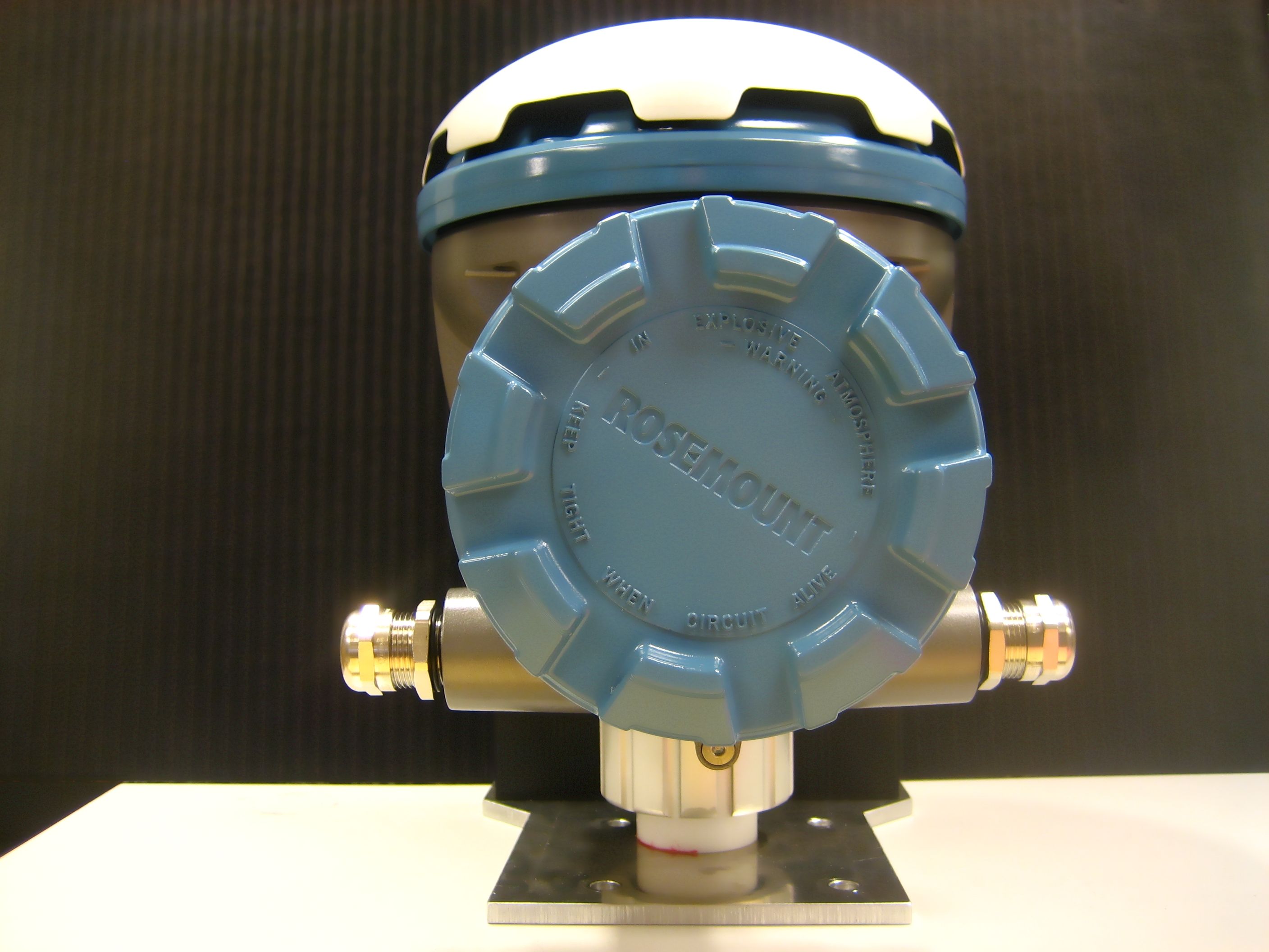
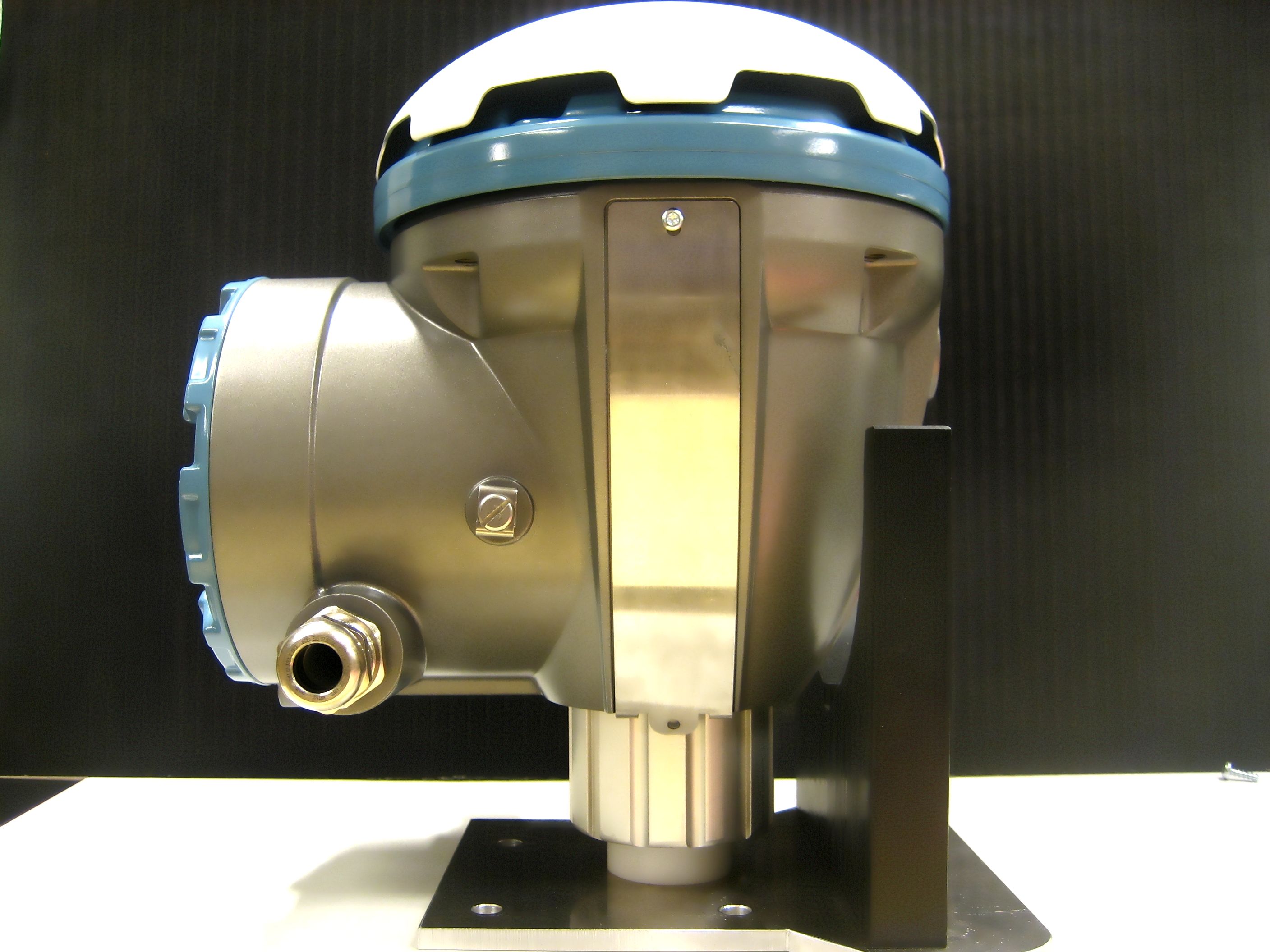
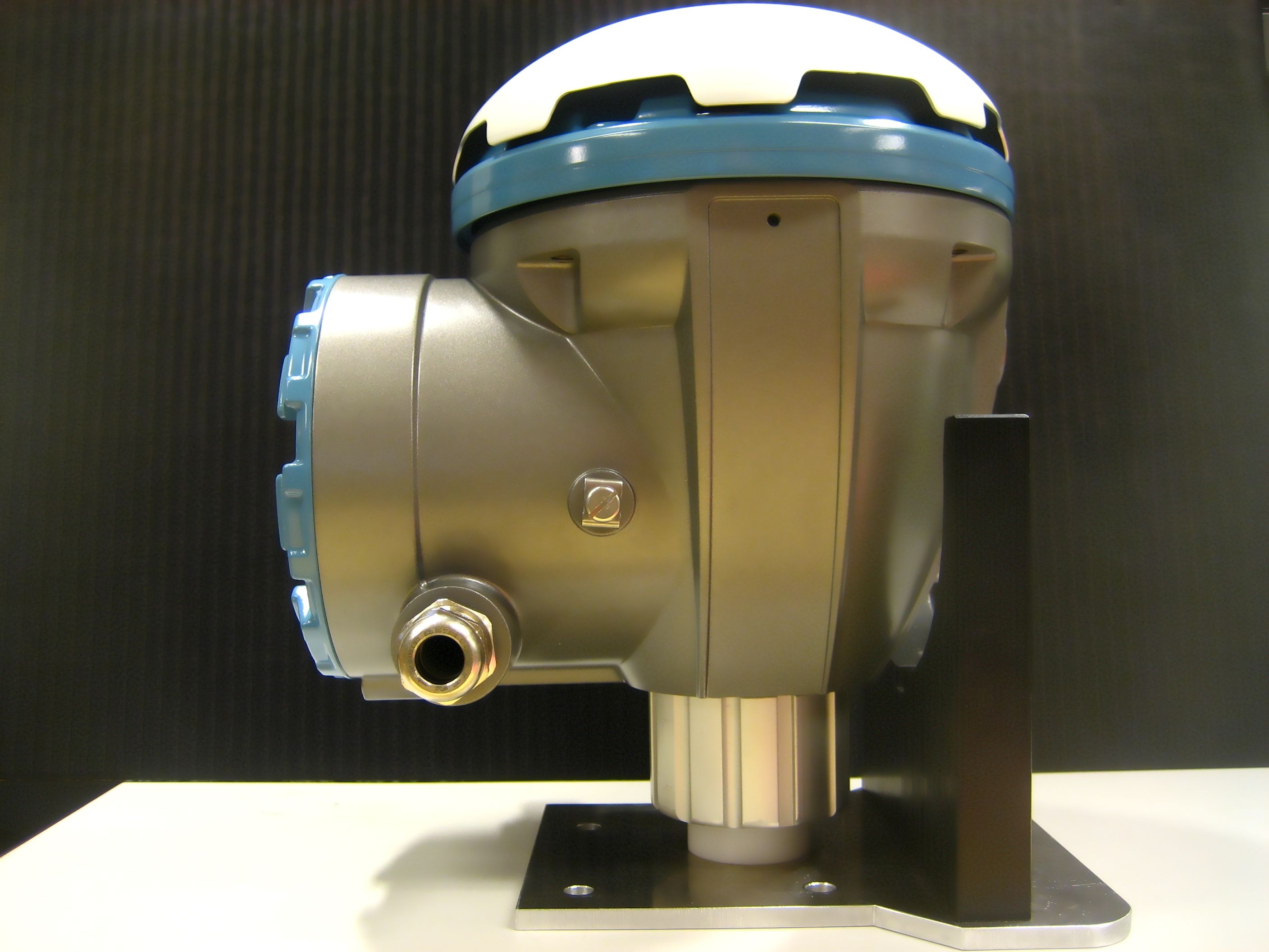
- Rosemount 5900S Radar Level Gauge
- Frequency Range
- 9501.00000000 - 10549.00000000
- Company
- Rosemount Tank Radar AB
- Country
- Sweden
Documents & Files
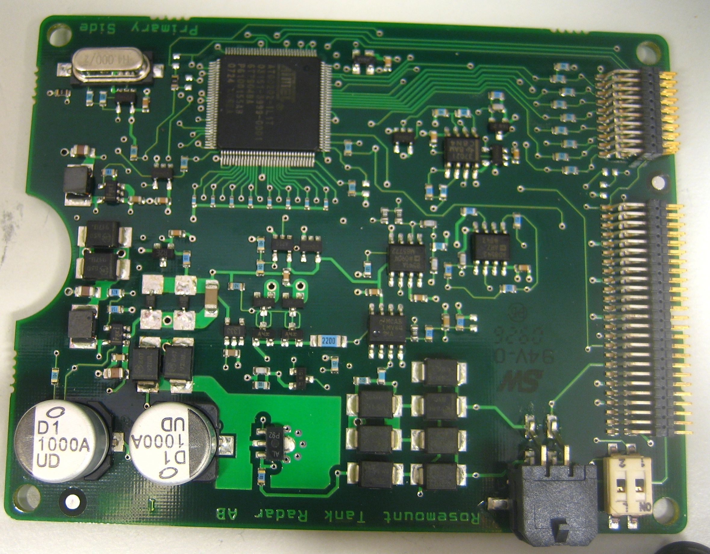
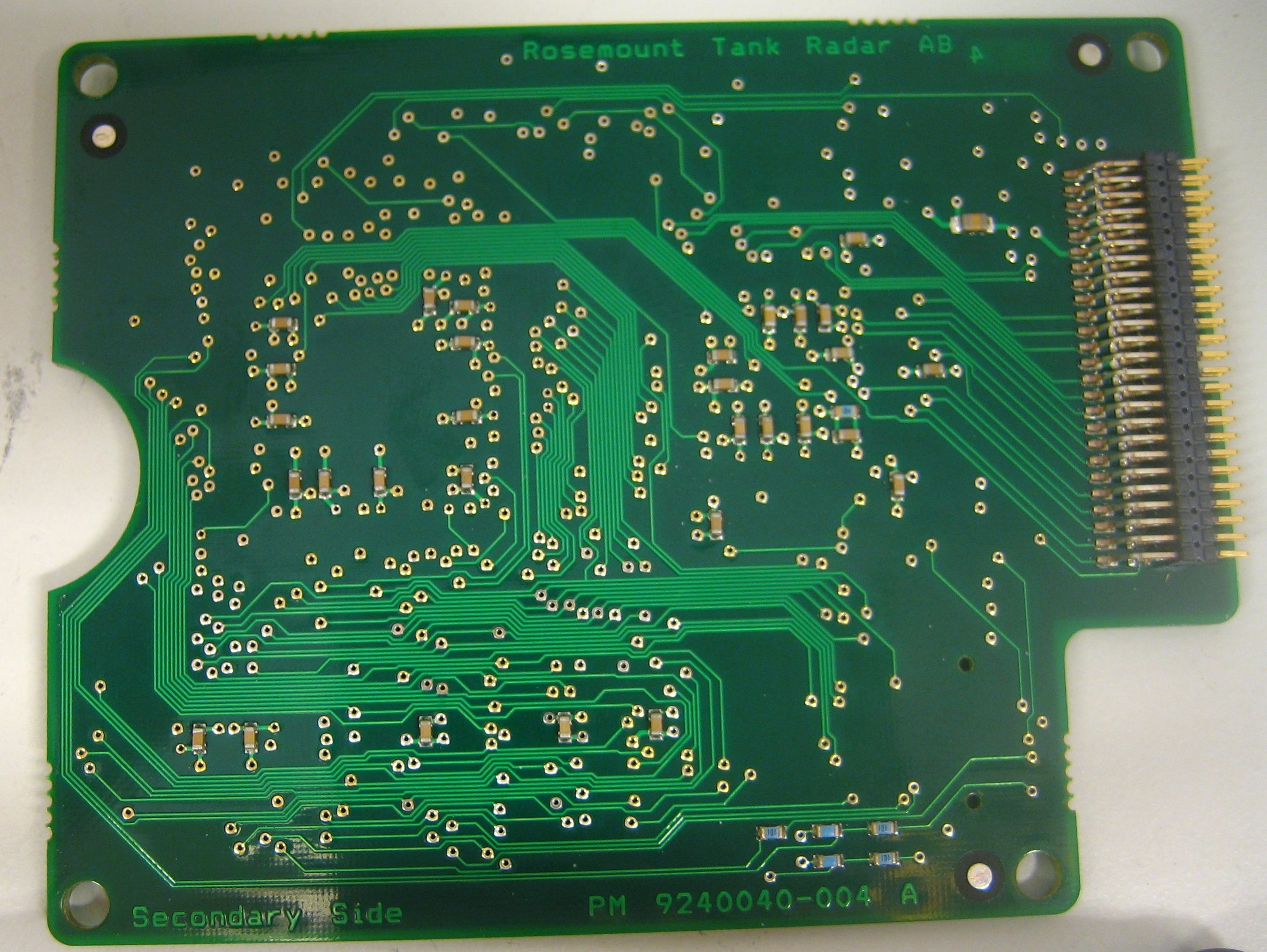
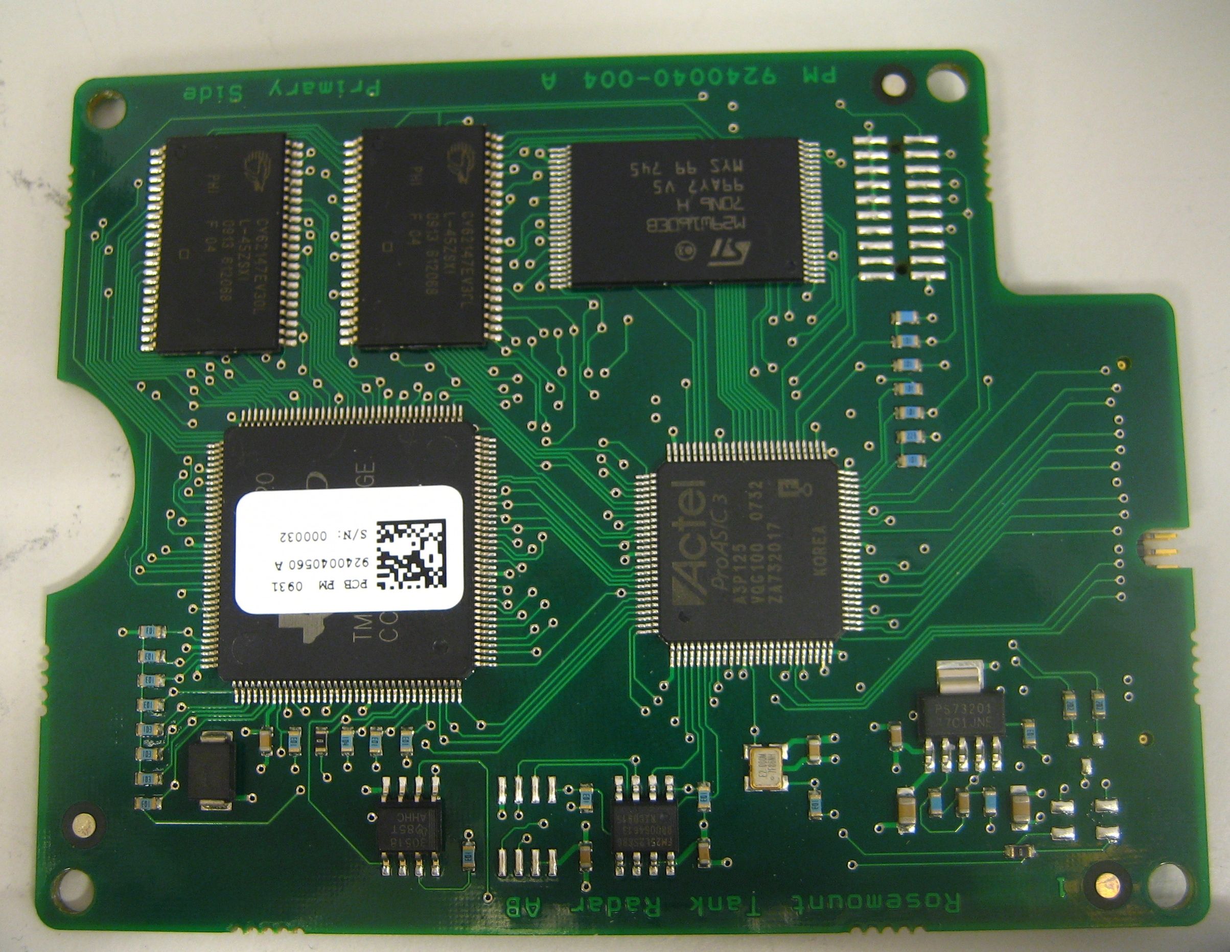
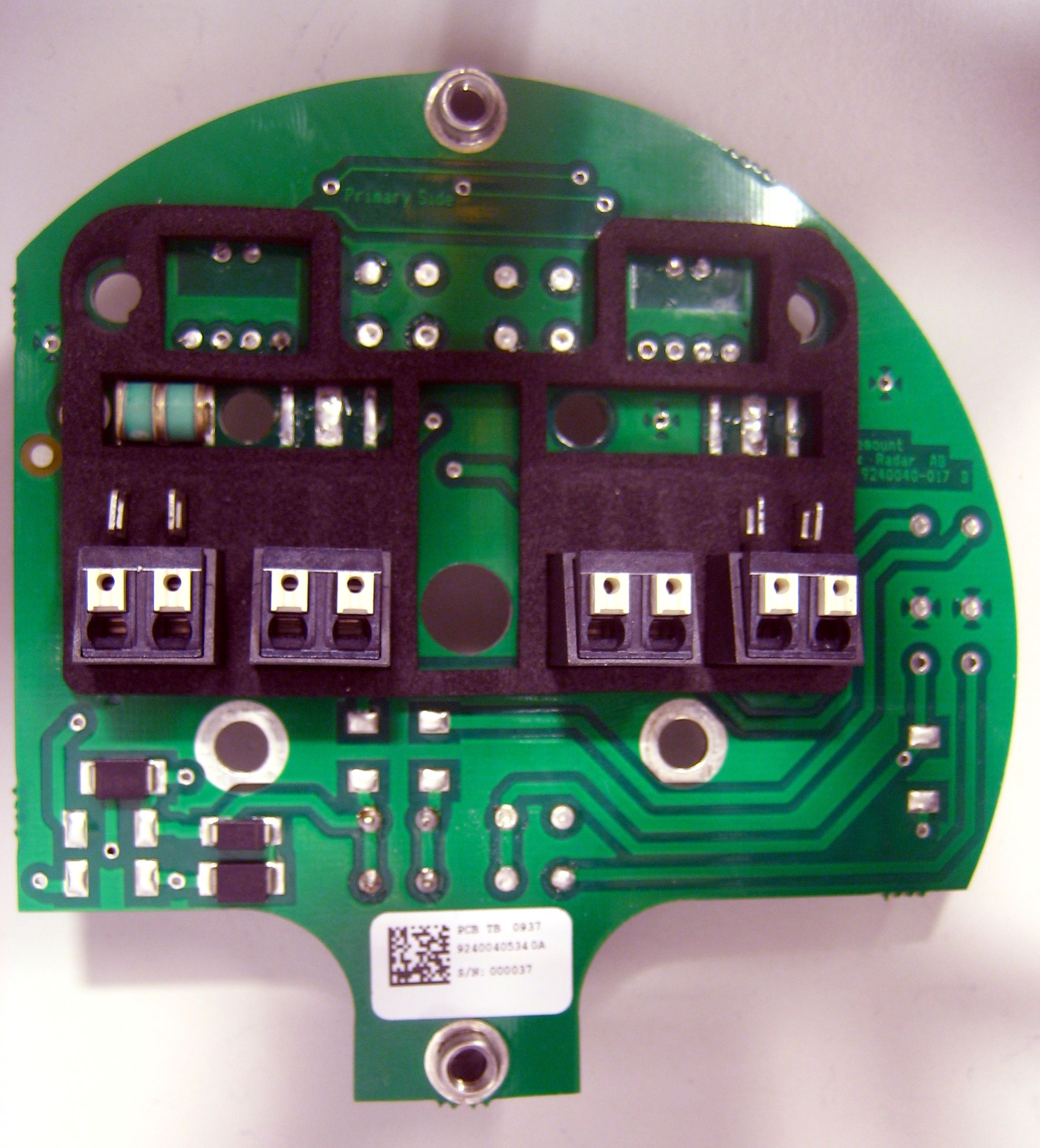
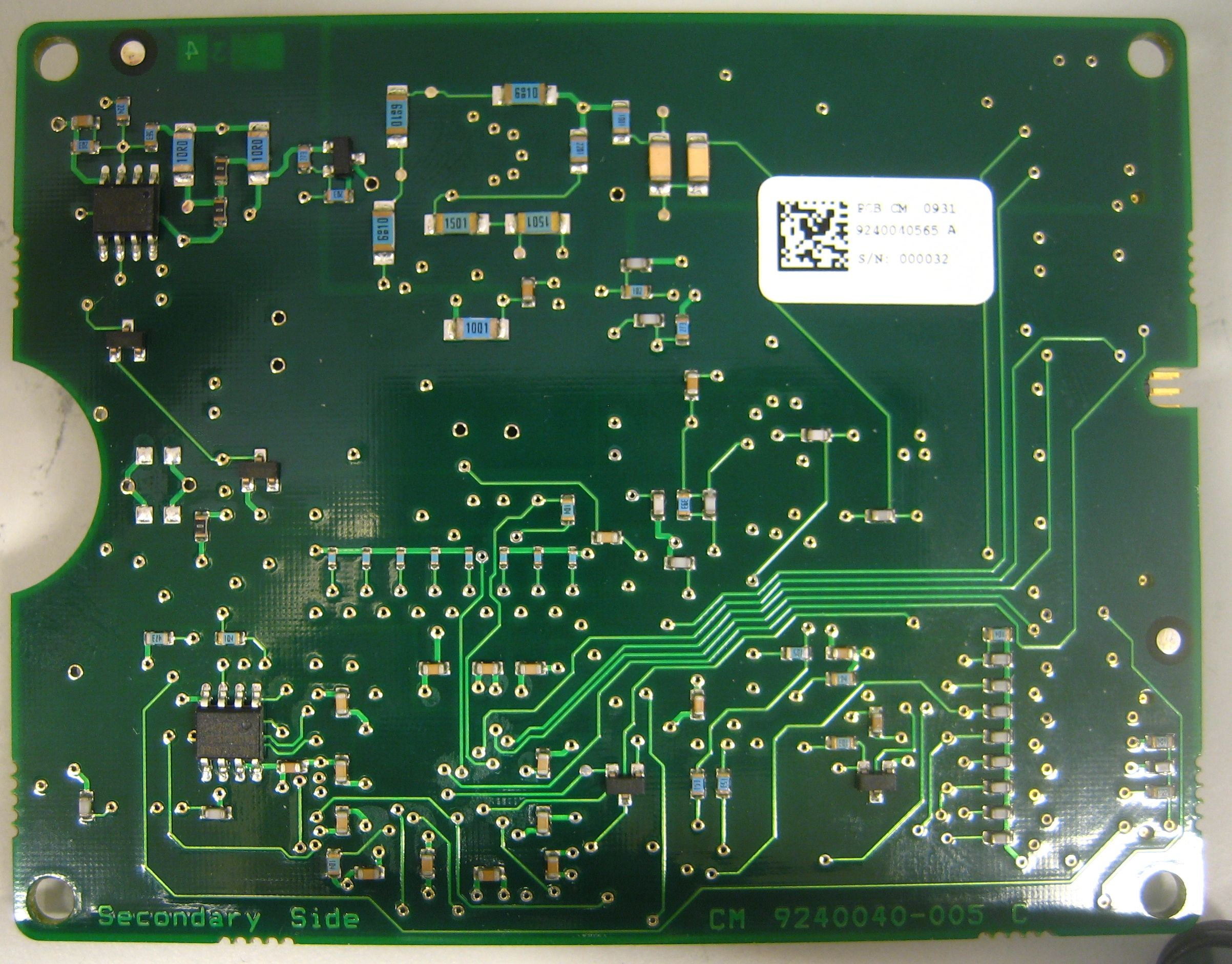
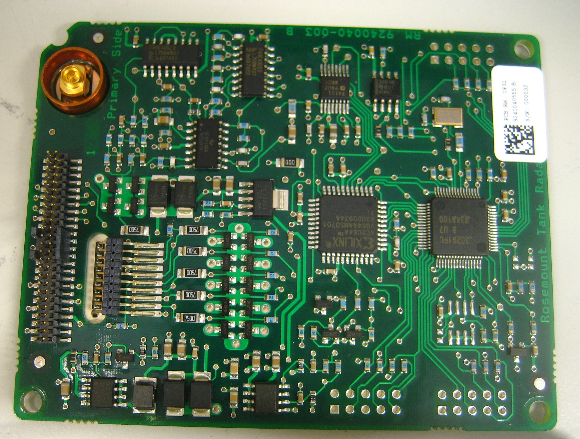
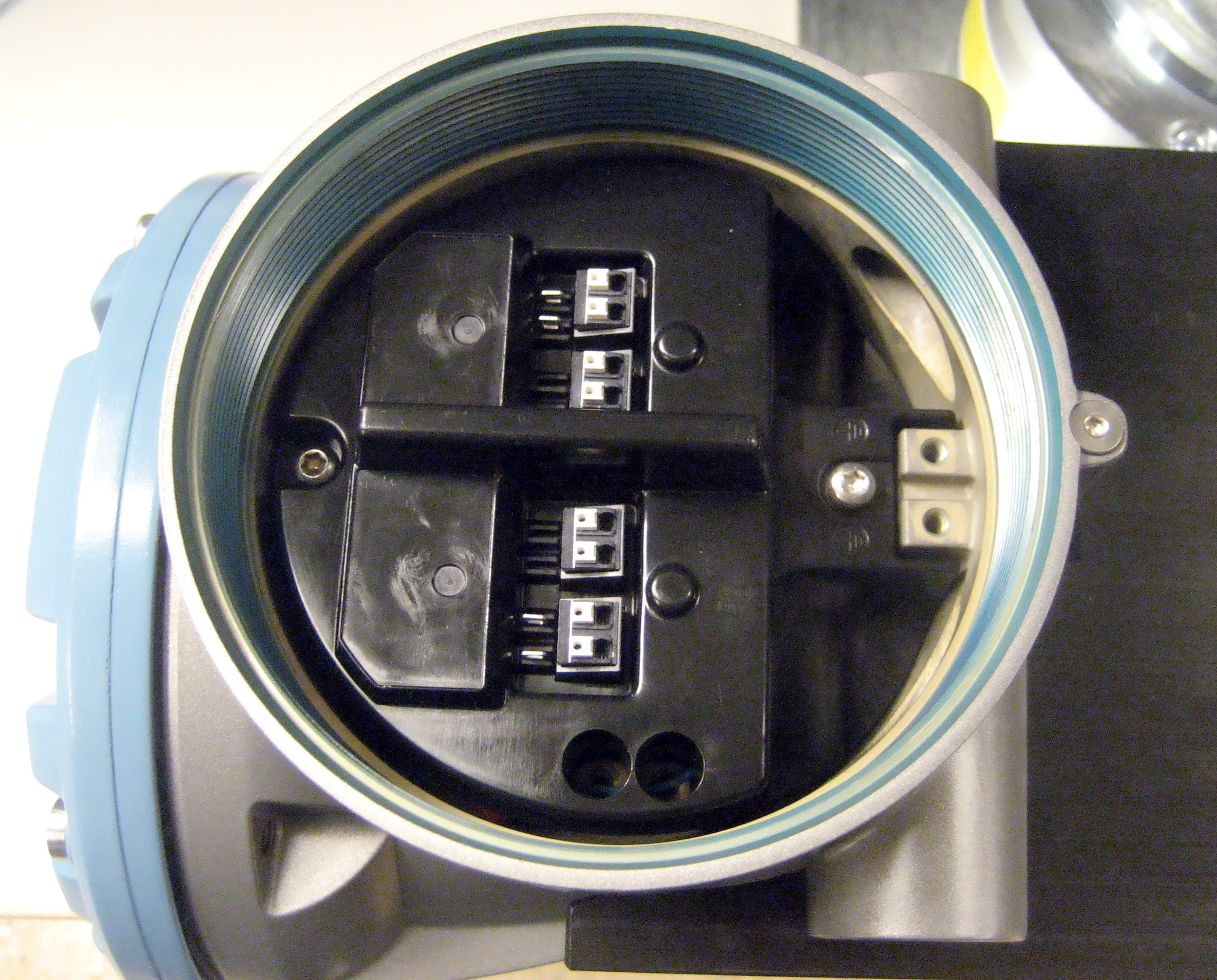
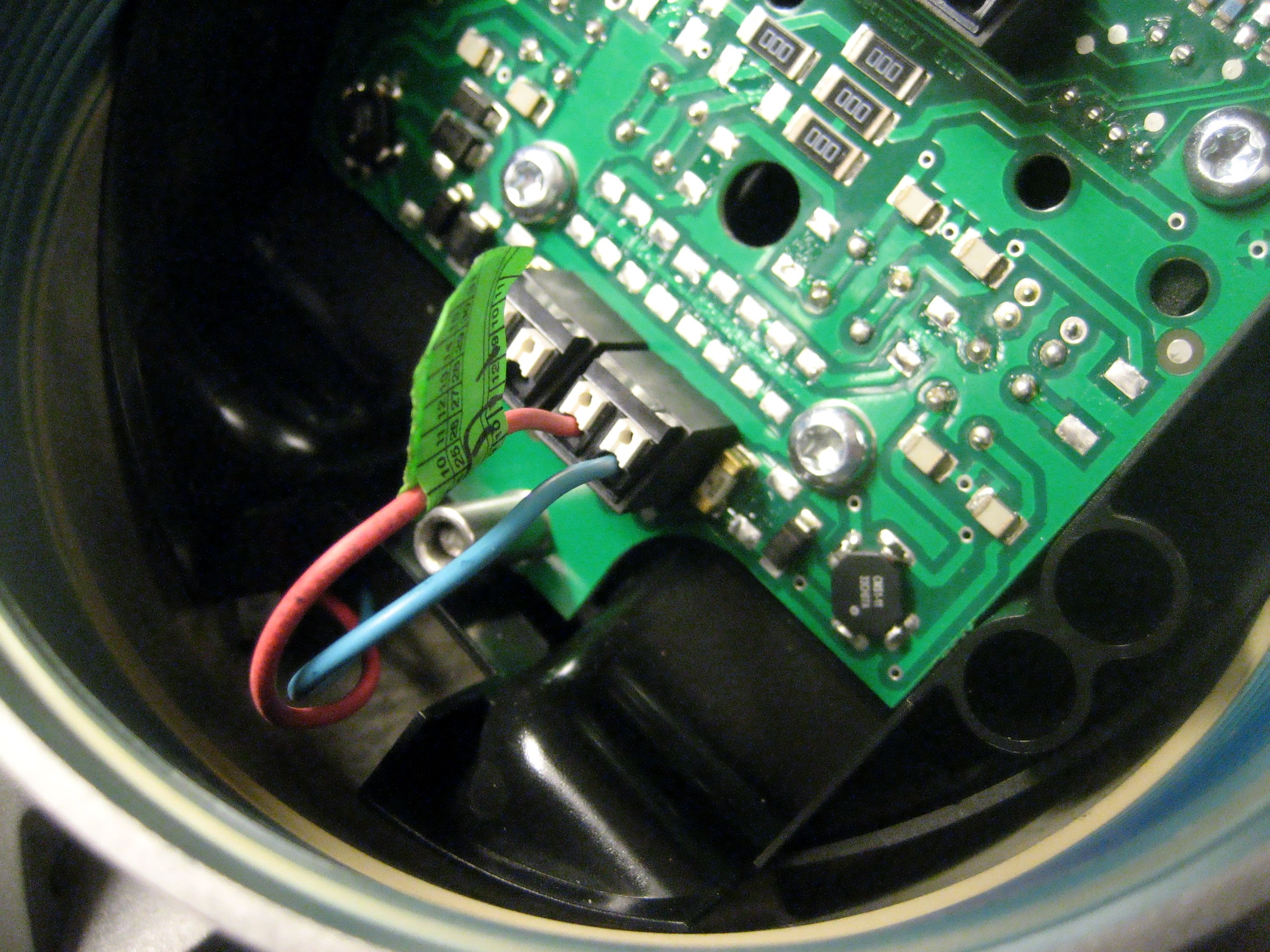
Document Text
Text extracted from the exhibit documents filed with the FCC. Open a document above to read the original.
Users Manual
www.rosemount-tg.com Reference Manual 300520EN, Rev AA November 2009 Rosemount 5900 Radar Level Gauge Preliminary Preliminary Reference Manual 300520EN, Rev AA November 2009 Rosemount 5900 www.rosemount-tg.com Rosemount 5900 Radar Level Gauge Cover Photo: 5900_coverphoto.tif NOTICE Read this manual before working with the product. For personal and system safety, and for optimum product performance, make sure you thoroughly understand the contents before installing, using, or maintaining this product. For equipment service or support needs, contact your local Emerson Process Management/Rosemount Tank Gauging representative. Spare Parts Any substitution of non-recognized spare parts may jeopardize safety. Repair, e.g. substitution of components etc, may also jeopardize safety and is under no circumstances allowed. Rosemount Tank Radar AB will not take any responsibility for faults, accidents, etc caused by non-recognized spare parts or any repair which is not made by Rosemount Tank Radar AB. Specific FCC Requirements (USA only) Rosemount 5900 generates and uses radio frequency energy. If it is not installed and used properly, that is, in strict accordance with the manufacturer ́s instructions, it may violate FCC regulations on radio frequency emission. Rosemount TankRadar 5900 has been FCC certified under test conditions which assume a metallic tank. Installation on a non-metallic tank is not certified, and is not allowed. The FCC certificate for Rosemount 5900 requires that the tank is closed as far as emitted radio energy is concerned. Tanks with open manholes, external-floating-roof tanks without still pipes etc. are not covered by the certificate. Preliminary Preliminary Reference Manual 300520EN, Rev AA November 2009 Rosemount 5900 Series www.rosemount-tg.com Table of Contents SECTION 1 Introduction 1.1Safety Messages . . . . . . . . . . . . . . . . . . . . . . . . . . . . . . . . . . . . 1-1 1.2Symbols. . . . . . . . . . . . . . . . . . . . . . . . . . . . . . . . . . . . . . . . . . . 1-2 1.3Manual Overview. . . . . . . . . . . . . . . . . . . . . . . . . . . . . . . . . . . . 1-3 1.4Service Support . . . . . . . . . . . . . . . . . . . . . . . . . . . . . . . . . . . . . 1-4 1.5Product Recycling/ Disposal1-5 1.6Packing Material . . . . . . . . . . . . . . . . . . . . . . . . . . . . . . . . . . . . 1-5 1.6.1Reuse . . . . . . . . . . . . . . . . . . . . . . . . . . . . . . . . . . . . . 1-5 1.6.2Recycling . . . . . . . . . . . . . . . . . . . . . . . . . . . . . . . . . . 1-5 1.6.3Energy recovery . . . . . . . . . . . . . . . . . . . . . . . . . . . . . 1-5 SECTION 2 Overview 2.1Introduction . . . . . . . . . . . . . . . . . . . . . . . . . . . . . . . . . . . . . . . . 2-1 2.2Components . . . . . . . . . . . . . . . . . . . . . . . . . . . . . . . . . . . . . . . 2-2 2.3System Overview. . . . . . . . . . . . . . . . . . . . . . . . . . . . . . . . . . . . 2-3 2.4Antennas . . . . . . . . . . . . . . . . . . . . . . . . . . . . . . . . . . . . . . . . . . 2-7 2.5Installation Procedure . . . . . . . . . . . . . . . . . . . . . . . . . . . . . . . . 2-9 SECTION 3 Installation 3.1Safety Messages . . . . . . . . . . . . . . . . . . . . . . . . . . . . . . . . . . . . 3-1 3.2Installation Considerations . . . . . . . . . . . . . . . . . . . . . . . . . . . . 3-3 3.2.1Horn Antenna Requirements . . . . . . . . . . . . . . . . . . . 3-4 3.2.2Parabolic Antenna Requirements . . . . . . . . . . . . . . . 3-6 3.2.3Still Pipe Antenna Requirements . . . . . . . . . . . . . . . 3-10 3.2.4LPG/LNG Antenna Requirements . . . . . . . . . . . . . . 3-13 3.3Mechanical Installation . . . . . . . . . . . . . . . . . . . . . . . . . . . . . . 3-18 3.3.1Horn Antenna . . . . . . . . . . . . . . . . . . . . . . . . . . . . . . 3-18 3.3.2Parabolic Antenna . . . . . . . . . . . . . . . . . . . . . . . . . . 3-20 3.3.3Array Antenna - Fixed version . . . . . . . . . . . . . . . . . 3-29 3.3.4Array Antenna - Hinged Hatch . . . . . . . . . . . . . . . . . 3-32 3.3.5LPG/LNG Antenna . . . . . . . . . . . . . . . . . . . . . . . . . . 3-36 3.4Electrical Installation . . . . . . . . . . . . . . . . . . . . . . . . . . . . . . . . 3-39 3.4.1Cable/conduit entries . . . . . . . . . . . . . . . . . . . . . . . . 3-39 3.4.2Grounding . . . . . . . . . . . . . . . . . . . . . . . . . . . . . . . . 3-39 3.4.3Cable Selection . . . . . . . . . . . . . . . . . . . . . . . . . . . . 3-40 3.4.4Hazardous Areas . . . . . . . . . . . . . . . . . . . . . . . . . . . 3-40 3.4.5Power Requirements . . . . . . . . . . . . . . . . . . . . . . . . 3-40 3.4.6Power Budget. . . . . . . . . . . . . . . . . . . . . . . . . . . . . . 3-40 3.4.7The Raptor Tankbus . . . . . . . . . . . . . . . . . . . . . . . . 3-41 3.4.8Typical installations . . . . . . . . . . . . . . . . . . . . . . . . . 3-42 3.4.9Wiring . . . . . . . . . . . . . . . . . . . . . . . . . . . . . . . . . . . . 3-43 3.4.10Terminal Blocks . . . . . . . . . . . . . . . . . . . . . . . . . . . . 3-44 3.4.11Wiring Diagrams. . . . . . . . . . . . . . . . . . . . . . . . . . . . 3-47 Preliminary Reference Manual 300520EN, Rev AA November 2009 Rosemount 5900 Series TOC-2 Table of Contents SECTION 4 Configuration 4.1Safety Messages . . . . . . . . . . . . . . . . . . . . . . . . . . . . . . . . . . . . 4-1 4.2Overview . . . . . . . . . . . . . . . . . . . . . . . . . . . . . . . . . . . . . . . . . . 4-2 4.2.1Basic Configuration . . . . . . . . . . . . . . . . . . . . . . . . . . 4-3 4.2.2Advanced Configuration . . . . . . . . . . . . . . . . . . . . . . . 4-3 4.2.3Configuration Tools . . . . . . . . . . . . . . . . . . . . . . . . . . 4-3 4.3Basic Configuration . . . . . . . . . . . . . . . . . . . . . . . . . . . . . . . . . . 4-4 4.3.1Tank Geometry . . . . . . . . . . . . . . . . . . . . . . . . . . . . . 4-4 4.3.2Environment . . . . . . . . . . . . . . . . . . . . . . . . . . . . . . . . 4-6 4.3.3Tank Shape . . . . . . . . . . . . . . . . . . . . . . . . . . . . . . . . 4-6 4.4Configurat…
Text truncated - open the document above for the full version.
Users Manual
Reference Manual 300520EN, Rev AA November 2009 6-9 Rosemount 5900 Series Section 6. Service and Troubleshooting 7. Click the Browse button to locate the flash program file. File extension *.cry are used for these files. 8. Click the Start Programming button. Now the Start Device Programming window appears. 9. Click the Start Programming button to activate device programming. If a 2160 Field Communication Unit (FCU) is used, a maximum of 25 devices can be programmed. If there are more devices the programming must be divided in two steps. 10. Update the TankMaster installation by adding the new *.ini files for the 5900 gauge to the TankMaster installation folder. For the 5900 two *.ini files are used, RLG.ini and RLG0xx.ini, where xx is the identification code of the 5900 gauge application software. The RLG.ini file is copied to the C:\Program Files\Rosemount\Server folder. The RLG0xx.ini file is copied to the C:\Program Files\Rosemount\Shared folder. Preliminary Reference Manual 300520EN, Rev AA November 2009 Rosemount 5900 Series 6-10 Section 6. Service and Troubleshooting 6.2.6Write ProtectionA Rosemount 5900 can be write protected to avoid unintentional configuration changes. 1. Start the TankMaster WinSetup program. 2. In the WinSetup workspace select the Logical View tab. 3. Click the right mouse button on the 5900 icon. 4. Choose the Write Protect option to open the Write Protect window. 5. Ensure that New State is set to Protected. 6. Click the OK button to save the new state and close the Write Protect window. Preliminary Reference Manual 300520EN, Rev AA November 2009 6-11 Rosemount 5900 Series Section 6. Service and Troubleshooting 6.2.7Write Protection Switch A switch can be used to prevent unauthorized changes in the Rosemount 5900 database. To write protect the 5900 do the following: 1. Check if there is any screw that is sealed. Contact Emerson Process Management/Rosemount Tank Gauging before breaking the seal if warranty is still valid. Completely remove the seal so that it does not damage the threads. 2. Loosen the screws and remove the cover. 3. Locate the write protection switch. 4. To write protect the 5900 move the left-hand switch to the ON position. 5. Check that contact surfaces on the transmitter housing and cover are clean. Replace the cover and tighten the screws. Write protection switch OFF ON Preliminary Reference Manual 300520EN, Rev AA November 2009 Rosemount 5900 Series 6-12 Section 6. Service and Troubleshooting 6.2.8Logging Measurement Data The Rosemount 5900 supports logging of diagnostic registers. This function is useful for verifying that the gauge works properly. The logging function can be accessed by using the TankMaster WinSetup program. To start logging do the following: 1. Start the TankMaster WinSetup program. 2. Select the 5900 gauge icon in the WinSetup workspace. 3. Click the right mouse button and choose Logging. 4. The Manual mode lets you start logging at any time. In Automatic mode you have to specify a Start and Stop time. 5. The resulting log file will not exceed the size specified by the Max File Size parameter. In automatic mode logging will proceed until the stop date and time is reached. In manual mode logging will proceed until it is stopped by clicking the Stop button. Logging will stop automatically when the number of log files is equal to the number given by the Max Log Files parameter. 6. The log file is stored as a plain text file and can be viewed in any word processing program. The log file is stored in the following folder: C:\Rosemount\Tankmaster\Setup\Log, where C is the disk drive where the TankMaster software is installed. The log file contains the same input registers as the View Diagnostic Registers window, see “Diagnostics” on page 6-7. You can can change which input registers to be included in the log file by configuring the View Diagnostic Registers window, see the Raptor System Configuration Manual (Document No. 300510EN) for more information. Preliminary Reference Manual 300520EN, Rev AA November 2009 6-13 Rosemount 5900 Series Section 6. Service and Troubleshooting 6.2.9Exchanging Gauge Electronics Jämför SIL; krav på att redogöra för reparation och underhåll av vissa delar, t.ex. Electronic Deposit Box (EDB). Preliminary Reference Manual 300520EN, Rev AA November 2009 Rosemount 5900 Series 6-14 Section 6. Service and Troubleshooting 6.2.10 Calibration Using the WinSetup Calibrate function The Calibrate function is a tool that lets you adjust a Rosemount 5900 level gauge in order to minimize the offset between actual (hand dipped) product levels and the values measured by the level gauge. By using the Calibrate function you can optimize measurement performance over the whole measurement range from the top to the bottom of the tank. The Calibration function calculates a new Calibration Distance based on fitting a straight line to the deviations between hand dipped levels and levels measured by the transmitter. For the Rosemount 5900 still pipe gauge the calibration function is specially suitable since a minor adjustment of the Scale Factor is often necessary. The radar propagation velocity is dependent on the inner diameter of the still pipe, and the Scale Factor parameter is used to adjust the transmitter to take this effect into account. Since the average diameter is often difficult to determine accurately a calibration is often needed. Procedure The adjustment process includes the following steps: 1. Recording the hand dipped ullage values and the corresponding level gauge values. 2. Entering the hand dipped levels and the level gauge values into WinSetup. 3. Inspect the resulting calibration graph and, if necessary, exclude measurement points which should not be used in the adjustment calculation. Required information Make sure that the following information is available when you intend to use the RTG Adjustment function in TankMaster WinSetup: • A list of hand dipped ullage values. • A list of RTG level val…
Text truncated - open the document above for the full version.
Attestation Statements
1 Prastalo, Dajana [PROCESS/RMT/GOTE]From: [email protected] Sent: den 7 december 2009 13:17 To: Prastalo, Dajana [PROCESS/RMT/GOTE] Subject: Pay.Gov Payment Confirmation THIS IS AN AUTOMATED MESSAGE. PLEASE DO NOT REPLY. Your transaction has been successfully completed. Payment Summary Application Name: Remittance Advice Form 159 Pay. gov Tracking ID: 2503I5BG Agency Tracking ID: 1702196 Account Holder Name: Linda Karlsson Transaction Type: Sale Billing Address: Box 13045 City: GOTHENBURG Zip/Postal Code: 40251 Country: SWE Card Type: Master Card Card Number: ************9236 Payment Amount: $1,395.00 Transaction Date: Dec 7, 2009 7:17:26 AM
Cover Letter(s)
2009-11-30 Request for Rosemoun t to be provid within this a Enclosed w If made pub covered in t Part 15. Rosemoun t more than 3 captioned d maintenanc installation o To assist in respectfully confidential employees. For the ab o processed t of those sam Yours Sinc e Dajana Pra s Senior E&D Emerson P r Rosemount E&D Depar r confidential t Tank Radar ded for all de application. In within our app blic, the infor this applicatio t Tank Radar 30,000 gauge device be per ce for the gau of all such ga assuring tha request gra ity is only pr o The gauge ove stated rea to grant in ac me Rules. erely, stalo D Approvals E rocess Mana t Tank Radar rtment ity r AB respectf tailed techni n support of plication is te mation migh on is a Rada r AB is one o es worldwide rformed by R uges. Additio auges worldw at we receive nt of confide oper as our g will consequ asons, Rose ccord with th Engineer agement r AB fully request cal informati this request , chnical infor t be used to ar Level Gau of the world’s e. Rosemoun Rosemount T onally, Rosem wide. e the full valu ntiality for al gauges only ently not be emount Tank e Commissi o s that in acco on, for the sc , we show th mation, whi c our disadva ge designed s largest prod nt Tank Rada Tank Radar’s mount Tank ue of our lice l information enter the st r subject to th Radar AB h on’s Rules a ordance with chematics, a e following. ch we deem t ntage in the for measur e ducers of lev ar AB require s personnel, w Radar AB m ense and prot mentioned a ream of com he examinatio ereby reque nd the state d h § 0.457 (d) and for the bl to be trade s marketplace ement in clos vel gauges an es that all ins who are the aintains rec o tect our com above. We fe merce under on of our com sts that our a d intention of , §0.459 con ock diagram secrets and p e. The equipm sed metallic t nd has sold a stallations of sole source ords on the s mpetitive post eel that a gra r strict contro mpetitors. application b f the Bureau nfidentiality ms contained proprietary. ment tanks under and installed the above- of sale and ture, we ant of ol of our be in creation d
ID Label/Location Info
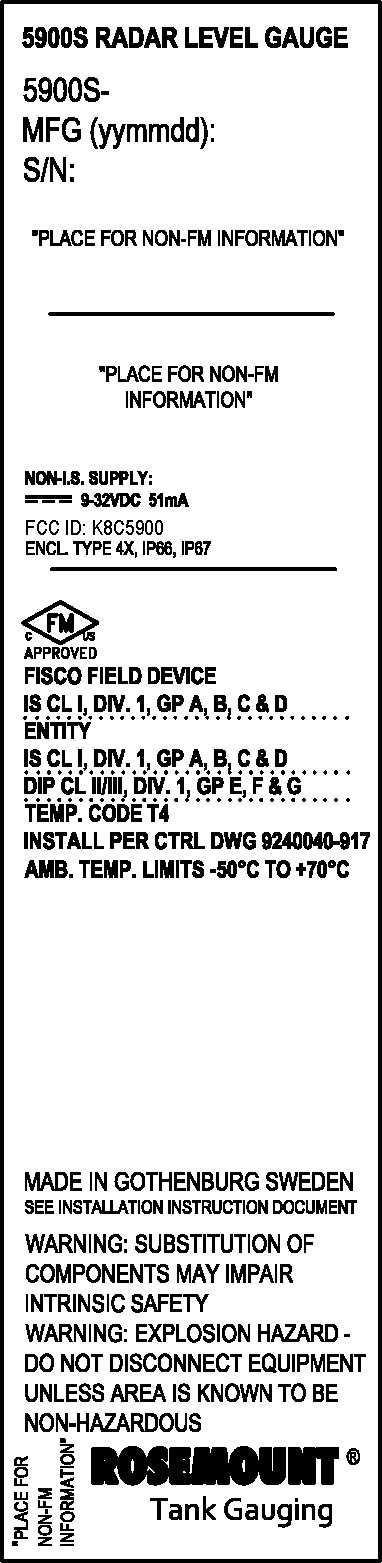
The ID label will be placed here on the device
Operational Description
2009-11-30 ROSEM Rosemount 5 antenna/prob and custody distances st o gauge/transm type in the s watertight to The radar g a varying frequ antenna, it is changed sligh the transmitt surface. This Modulated C The 5900 co n CM), microw compartment microwave u Please indic a Yours Since r Dajana Pras t Senior E&D Emerson Pr o Rosemount T E&D Depart MOUNT 59 5900S Series be inside the t transfer requir ored locally mitter consists same gauge se protect again auge transmit uency, around s mixed with t htly during th ted and the re s signal provid Continuous Wa nsists of an al wave unit (RM t integrated w unit to the ante ate immediate rely, talo Engineer, A p ocess Managem Tank Radar A tment 900S SER is a radar lev tank. Rosemo rements. The in the mem o of a transmitt eries, minimiz nst salt spray a ts microwaves d 10 GHz for the signal that he time it take eceived signal des a measured ave). The FM uminum enclo M), signal proc with the housin enna. ly if you nee d pprovals ment AB RIES - A b vel gauge that ount 5900S, is radar level ga ory of the ga ter head and a zing spare par atmospheres in s towards the 5900S. When is being trans s for the echo , the result is d value with h MCW-method i osure containi cessing electro ng. A special o d additional in brief descrip provides outs s a non-contac auge measures auge, it calcu an antenna. Th rts requiremen n coastal areas e surface of th n the signal ha smitted at that o signal to trav a signal with high accuracy is based on a r ing an Electro onics (PCB PM output is the w nformation fro ption of the standing reliab ct, FMCW ba s the distance ulates the lev he transmitter nts. The enclo s. he liquid. Th as travelled do t moment. The vel down to th h a low freque . This is called radar sweep w onics Unit (ED M). The extern waveguide pas m us! e equipment bility with no ased, high-pre to the surface vel of the li head can be c osure of the t e microwave own to the liqu e frequency o he surface and ency, proporti d the FMCW- with varying fr DB) with comm nal connection ssing the micro t: moving parts ecision gauge e of the produc quid’s surfac combined with transmitter he signal has a uid surface an of the transmit d back again. W ional to the d -method (Freq requency. munication ci ns are made in owaves from s and only the for inventory ct. Using tank ce. The radar h any antenna ad is air- and continuously nd back to the tted signal has When mixing distance to the quency rcuit (PCB n a terminal the e y k r a d y e s g e
Test Report
CETECOM ICT Services GmbH Untertürkheimer Str. 6-10, 66117 Saarbruecken Phone: +49 (0) 681 598-0 Fax: -9075 RSC-Laboratory Test report no.:1-1490-01-03/09 Date: 2009-11-02 Page 1 of 63 Recognized by the Federal Communications Commission Anechoic chamber registration no.: 90462 (FCC) Anechoic chamber registration no.: IC 3463A-1 TCB ID: DE 0001 Accredited by the German Accreditation Council DAR–Registration Number DAT-P-176/94-D1 Accredited Bluetooth ® Test Facility (BQTF) Test report no. : 1-1490-01-03/09 Applicant : Rosemount Tank Radar AB Type : Rosemount 5900S Radar Level Gauge Test Standard : FCC Part 15.209 RSS210 Issue 7 FCC ID : K8C5900 Certification No. IC : 2827A-5900 CETECOM ICT Services GmbH Untertürkheimer Str. 6-10, 66117 Saarbruecken Phone: +49 (0) 681 598-0 Fax: -9075 RSC-Laboratory Test report no.: 1-1490-01-03/09 Date: 2009-11-02 Page 2 of 63 Table of contents 1 GENERAL INFORMATION ................................................................................................................................... 3 1.1. ADMINISTRATIVE DATA OF THE TEST FACILITY..................................................................................................... 3 1.1.1 Identification of the testing laboratory ......................................................................................................... 3 1.2. NOTES................................................................................................................................................................... 3 1.3 DETAILS OF APPLICANT......................................................................................................................................... 4 1.4 APPLICATION DETAILS.......................................................................................................................................... 4 1.5 TEST ITEM............................................................................................................................................................. 5 1.6 TEST SETUP........................................................................................................................................................... 6 1.7 TEST SPECIFICATIONS............................................................................................................................................ 6 2 STATEMENT OF COMPLIANCE .......................................................................................................................... 7 2.1 SUMMARY OF MEASUREMENT RESULTS................................................................................................................ 7 2.1.1 CFR 47 Part 15 Radio frequency devices / RSS 210 .................................................................................... 7 3 MEASUREMENTS AND RESULTS ....................................................................................................................... 8 3.1 EMISSSION BANDWIDTH 3.2 CONDUCTED OUTPUT POWER 3.3 FIELD STRENGTH OF THE FUNDAMENTAL 3.4 RADIATED SPURIOUS EMISSIONS 3.5 CONDUCTED EMISSIONS 3.6 FREQUENCY STABILITY 4 USED TESTEQUIPMENT ...................................................................................................................................... 47 5 ANNEX A: PHOTOGRAPHS OF TEST SITE ..................................................................................................... 49 6 ANNEX B: EXTERNAL PHOTOGRAPHS OF THE EQUIPMENT................................................................. 51 7 ANNEX C: INTERNAL PHOTOGRAPHS OF THE EQUIPMENT.................................................................. 63 CETECOM ICT Services GmbH Untertürkheimer Str. 6-10, 66117 Saarbruecken Phone: +49 (0) 681 598-0 Fax: -9075 RSC-Laboratory Test report no.: 1-1490-01-03/09 Date: 2009-11-02 Page 3 of 63 1 General information 1.1. Administrative data of the test facility 1.1.1 Identification of the testing laboratory Company name: Cetecom ICT Services GmbH Address: Untertürkheimerstr. 6-10 D-66117 Saarbruecken Germany Laboratory accreditation: DAR-Registration No. DAT-P-176/94-D1 Bluetooth Qualification Test Facility (BQTF) Federal Communications Commission (FCC) Identification/Registration No : 90462 Responsible for testing laboratory: Nicolas Stamber Phone: +49 681 598 0 Fax: +49 681 598 9075 email: [email protected] 1.2. Notes The test results of this test report relate exclusively to the test item specified in 1.5. The CETECOM ICT Services GmbH does not assume responsibility for any conclusions and generalizations drawn from the test results with regard to other specimens or samples of the type of the equipment represented by the test item. The test report may only be reproduced or published in full. Reproduction or publication of extracts from the report requires the prior written approval of the CETECOM ICT Services GmbH. ............................................................................................................... Responsible for testing laboratory (Karsten Geraldy) ................................................................................................................ Responsible for test report ( Nicolas Stamber) CETECOM ICT Services GmbH Untertürkheimer Str. 6-10, 66117 Saarbruecken Phone: +49 (0) 681 598-0 Fax: -9075 RSC-Laboratory Test report no.: 1-1490-01-03/09 Date: 2009-11-02 Page 4 of 63 1.3 Details of Applicant Name : Rosemount Tank Radar AB Street : Gamlestadsvägen 18 B Town : SE-40251 Göteborg Country : Sweden Phone : +46 31 33 70 000 Fax : +46 31 25 30 22 Contact person Name : Mr. Mikael Kleman Phone : +46 13 23 60 05 Fax : +46 13 23 60 60 E–Mail : [email protected] 1.4 Application Details Date of test : 05.–07.10.2009, 19.–20.10.2009 Person(s) who have been : Mr. Mikael Kleman present during the test CETECOM ICT Services GmbH Untertürkheimer Str. 6-10, 66117 Saarbruecken Phone: +49 (0) 681 598-0 Fax: -9075 RSC-Laboratory Test report no.: 1-1490-01-03/09 Date: 2…
Text truncated - open the document above for the full version.
Test Setup Photos
CETECOM ICT Services GmbH Untertürkheimer Str. 6-10, 66117 Saarbruecken Phone: +49 (0) 681 598-0 Fax: -9075 RSC-Laboratory Test report no.: 1-1490-01-03/09 Date: 2009-11-02 Page 50 of 63 Photo 2 (Radiated Emissions) CETECOM ICT Services GmbH Untertürkheimer Str. 6-10, 66117 Saarbruecken Phone: +49 (0) 681 598-0 Fax: -9075 RSC-Laboratory Test report no.: 1-1490-01-03/09 Date: 2009-11-02 Page 51 of 63 Photo 3 (Radiated Emissions) CETECOM ICT Services GmbH Untertürkheimer Str. 6-10, 66117 Saarbruecken Phone: +49 (0) 681 598-0 Fax: -9075 RSC-Laboratory Test report no.: 1-1490-01-03/09 Date: 2009-11-02 Page 52 of 63 Photo 4 (Radiated Emissions) CETECOM ICT Services GmbH Untertürkheimer Str. 6-10, 66117 Saarbruecken Phone: +49 (0) 681 598-0 Fax: -9075 RSC-Laboratory Test report no.: 1-1490-01-03/09 Date: 2009-11-02 Page 53 of 63 Photo 5 (Radiated Emissions) CETECOM ICT Services GmbH Untertürkheimer Str. 6-10, 66117 Saarbruecken Phone: +49 (0) 681 598-0 Fax: -9075 RSC-Laboratory Test report no.: 1-1490-01-03/09 Date: 2009-11-02 Page 54 of 63 Photo 6 (Radiated Emissions) CETECOM ICT Services GmbH Untertürkheimer Str. 6-10, 66117 Saarbruecken Phone: +49 (0) 681 598-0 Fax: -9075 RSC-Laboratory Test report no.: 1-1490-01-03/09 Date: 2009-11-02 Page 55 of 63 Photo 7 (Radiated Emissions) CETECOM ICT Services GmbH Untertürkheimer Str. 6-10, 66117 Saarbruecken Phone: +49 (0) 681 598-0 Fax: -9075 RSC-Laboratory Test report no.: 1-1490-01-03/09 Date: 2009-11-02 Page 56 of 63 6 Annex B: External Photographs of the Equipment Photo 8 (EUT) CETECOM ICT Services GmbH Untertürkheimer Str. 6-10, 66117 Saarbruecken Phone: +49 (0) 681 598-0 Fax: -9075 RSC-Laboratory Test report no.: 1-1490-01-03/09 Date: 2009-11-02 Page 57 of 63 Photo 9 (EUT waveguide) CETECOM ICT Services GmbH Untertürkheimer Str. 6-10, 66117 Saarbruecken Phone: +49 (0) 681 598-0 Fax: -9075 RSC-Laboratory Test report no.: 1-1490-01-03/09 Date: 2009-11-02 Page 58 of 63 Photo 10 (EUT with horn antenna mounted) CETECOM ICT Services GmbH Untertürkheimer Str. 6-10, 66117 Saarbruecken Phone: +49 (0) 681 598-0 Fax: -9075 RSC-Laboratory Test report no.: 1-1490-01-03/09 Date: 2009-11-02 Page 59 of 63 Photo 11 (EUT with horn antenna mounted) CETECOM ICT Services GmbH Untertürkheimer Str. 6-10, 66117 Saarbruecken Phone: +49 (0) 681 598-0 Fax: -9075 RSC-Laboratory Test report no.: 1-1490-01-03/09 Date: 2009-11-02 Page 60 of 63 Photo 12 (EUT with parabolic antenna mounted) CETECOM ICT Services GmbH Untertürkheimer Str. 6-10, 66117 Saarbruecken Phone: +49 (0) 681 598-0 Fax: -9075 RSC-Laboratory Test report no.: 1-1490-01-03/09 Date: 2009-11-02 Page 61 of 63 Photo 13 (EUT with parabolic antenna mounted) CETECOM ICT Services GmbH Untertürkheimer Str. 6-10, 66117 Saarbruecken Phone: +49 (0) 681 598-0 Fax: -9075 RSC-Laboratory Test report no.: 1-1490-01-03/09 Date: 2009-11-02 Page 62 of 63 Photo 13 (test tank) CETECOM ICT Services GmbH Untertürkheimer Str. 6-10, 66117 Saarbruecken Phone: +49 (0) 681 598-0 Fax: -9075 RSC-Laboratory Test report no.: 1-1490-01-03/09 Date: 2009-11-02 Page 63 of 63 7 Annex C: INTERNAL PHOTOGRAPHS OF THE EQUIPMENT - see attachment
Contact Information
Applicant
Dajana Prastalo(E&D, Approvals)
Test Firm
cetecom advanced GmbHGerald Schmidt
Technical Specifications
| # | Rule Parts | Frequency Range | Power Output |
|---|---|---|---|
| 1 | 15C | 9.50 GHz - 10.55 GHz | - |
Other Applications from Rosemount Tank Radar AB
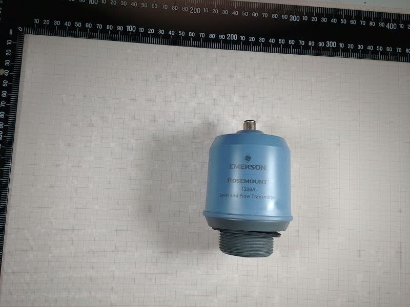
K8C1208CLB
May 09, 2023Level and Flow Transmitter
Equipment Class
LPR - Level Probing Radar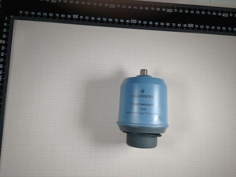
K8C1208LB
Dec 15, 2022Rosemount 1208A Level transmitter
Equipment Class
DTS - Digital Transmission System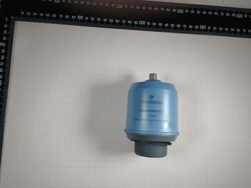
K8C1208L
Dec 15, 2022Rosemount 1208A Level transmitter
Equipment Class
LPR - Level Probing Radar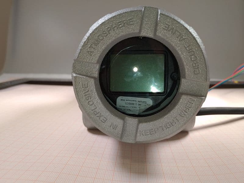
K8C3408T
Oct 20, 2022Rosemount 3408 Level Transmitter
Equipment Class
LPR - Level Probing Radar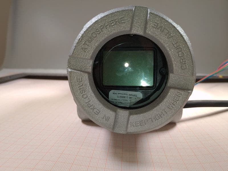
K8C3408TB
Oct 20, 2022Rosemount 3408 Level Transmitter
Equipment Class
LPR - Level Probing Radar