K8CLOOPRADARRadar Level Gauge
Rosemount Tank Radar AB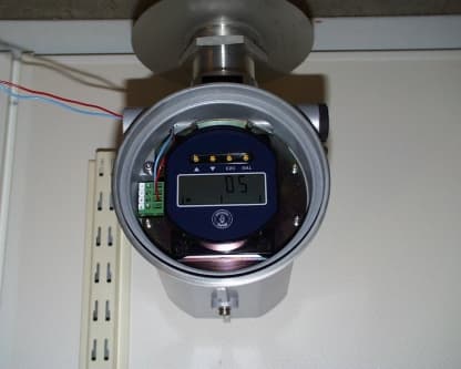
Click to zoom
Application Details
- Equipment Class
- DXX - Part 15 Low Power Communication Device Transmitter
- Date of Grant
- Oct 24, 2000
- Application Purpose
- Original Equipment
- Date of Application
- Apr 24, 2000
- Equipment Note
- Radar Level Gauge
- Frequency Range
- 6300.00000000 - 6300.00000000
- Company
- Rosemount Tank Radar AB
- Country
- Sweden
Documents & Files
Document Text
Text extracted from the exhibit documents filed with the FCC. Open a document above to read the original.
Users Manual
User ́s Guide Preliminary edition (i) User ́s Guide First edition Edition 1.Ref. No: 307010E Copyright © April 2000 Saab Marine Electronics AB (ii) Edition 1.Ref. No: 307010E Copyright © April 2000 Saab Marine Electronics AB The contents, descriptions and specifications within this manual is subject to change without notice. Saab Marine Electronics AB accepts no responsibility for any errors that may appear in this manual. Trademarks HART is a registered trademark of HART Communication Foundation. LoopRadar is a trademark of Saab Marine Electronics AB. TankRadar is a registered trademark of Saab Marine Electronics AB. Spare Parts Any substitution of non-recognized spare parts may jeopardize safety. Repair, e.g. substitution of components etc., may also jeopardize safety and is under no cir- cumstances allowed. Saab Tank Control will not take any responsibility for faults, accidents, etc. caused by non-recognized spare parts or any repair which is not made by Saab Tank Control. Safety This manual applies to equipment covered by certificate number SIRA 00ATEX2052X. The equipment may be used with flammable gases and vapours with apparatus groups IIA, IIB and IIC and with temperature classes T1 to T4 inclusive. The equipment is only certified for use in ambient temperatures in the range -40 °C to +70 °C and should not be used outside this range. The Saab LoopRadar transmitter must be installed by suitably trained personnel according to the instructions in this manual and in accordance with the applicable code of practice. The certificate number has an ’X’ suffix which indicates that special conditions for cable capacitance apply. For specification of cable capacitance see the certificate. Repair of this equipment shall be carried out in accordance with the applicable code of practice. ( iii ) Edition 1.Ref. No: 307010E The various warning messages shown in the Userís Guide are indicated as follows: Indicates that incorrect usage may result in personal injury or malfunctioning instruments. ! Caution Indicates a potentially hazardous situation which could result, if not avoided, in death or serious injury. ! Warning ! Warning Don¥t open lower nut if tank is pressurised or contains hazardous product. (iv) Edition 1.Ref. No: 307010E Contents About this manual....................................................... vi 1Product Description ...................................... 1-1 1.1Features................................................................................ 1-1 1.2Measurement Principle.......................................................... 1-2 2Mechanical Installation ................................. 2-1 2.1Requirements........................................................................ 2-1 2.2Dimensions........................................................................... 2-3 2.3Tools...................................................................................... 2-4 2.4Mounting the Cone Antenna .................................................. 2-5 2.5Installation Hints..................................................................... 2-7 3Electrical Installation.....................................3-1 3.1Connecting the LoopRadar ................................................... 3-1 3.2Cables................................................................................... 3-3 3.3Load...................................................................................... 3-3 3.4Power supply......................................................................... 3-3 3.5Grounding.............................................................................. 3-3 4Transmitter Setup .......................................... 4-1 4.1Configuration ......................................................................... 4-2 4.1.1 General Settings........................................................ 4-2 4.1.2 Basic Tank Geometry................................................ 4-2 4.1.3 Advanced Tank Geometry........................................ 4-3 4.2Analog Output........................................................................ 4-4 (v) Edition 1.Ref. No: 307010E 4.3Volume Calculation................................................................ 4-5 4.4Disturbance Echo Handling. .................................................. 4-7 4.4.1 Noise Table................................................................ 4-7 5Using the Display Panel................................ 5-1 5.1Display Panel......................................................................... 5-1 5.1.1Display....................................................................... 5-1 5.1.2Keys........................................................................... 5-2 5.2Basic Key Parameter List...................................................... 5-3 5.3Navigating the Display Panel Menus ..................................... 5-5 5.4Configuration ......................................................................... 5-6 5.5Volume Calculation................................................................ 5-8 5.6Setting up the Analog Output...............................................5-10 5.7Disturbance Echo Handling ................................................. 5-11 5.7.1Setting up a Noise Threshold Table ....................... 5-11 6Technical Information ................................... 6-1 7Troubleshooting............................................ 7-1 Index............................................................................... I Appendix 1: Key Parameters ................................. A1-1 (vi) Edition 1.Ref. No: 307010E About this manual The main purpose of Userís Guide is to act as guide to installing and operating the Saab LoopRadar. It is not intended to cover service tasks such as changing circuit boards or internal software. Chapter 1 reviews some basic concepts of radar based level gauging. Chapter 2 describes how to assemble a gauge and how…
Text truncated - open the document above for the full version.
Cover Letter(s)
Request for confidentiality Saab Tank Control respectfully requests that in accordance with §§ 0.457 (d), 0.459 confidentiality be provided for all detailed technical information, for the schematics, and for the block diagrams contained within this application. In support of this request, we show the following. Enclosed within our application is technical information, which we deem to be trade secrets and proprietary. If made public, the information might be used to our disadvantage in the marketplace. The equipment covered in this application is a Radar Level Gauge designed for measurement under open conditions under Part 15. To assist in assuring that we receive the full value of our license and protect our competitive posture, we respectfully request grant of confidentiality for all information mentioned above. We feel that a grant of confidentiality is only proper as our gauges only enters the stream of commerce under strict control of our employees. The gauge will consequently not be subject to the examination of our competitors. For the above stated reasons, Saab Tank Control hereby requests that our application be processed to grant in accord with the Commission’s Rules and the stated intention of the Bureau in creation of those same Rules. Göteborg 1999-05-10 Per Karlsson, Product manager
Cover Letter(s)
Correction of frequency tolerance This correction refers to Form 731 Confirmation Number EA97436 (FCC ID: K8CLOOPRADAR); By mistake I entered an incorrect value (0,01%) of the Frequency Tolerance in form 731. The correct value should be 1,6%. Best regards Per Karlsson Saab Marine Electronics AB Box 13045 SE-402 51 Göteborg Sweden Phone: +46 31 3370348 Mobile: +46 70 5808094 Fax: +46 31 253022 Mail: [email protected]
Internal Photos
Chassi assembly back view Chassi assembly front view Chassi assembly left view Chassi assembly right view: Chassis assembly top view Chassis assembly bottom view
Internal Photos
CAK-10 PCB front view CAK-10 back view CFK10 PCB front view CFK10 PCB back view CHK10 PCB front view CHK10 PCB back view CRF10 PCB front view CRF 10 back view
Operational Description
Loop Powered Microwave Level Gauge Technical Description Loop-powered Microwave Level Gauge Features ßNo moving parts and no contact with the liquid ßNo maintenance and high reliability ßHigh sensitivity ßLoop-powered ßAnalog 4 - 20mA and digital HART ‚ outputs ßHigh flexibility with interchangeable gauge heads and antennas ßDifferent antennas available for best performance in various applications ßHigh accuracy ßInteractive setup on PC with Windows based software, HART ‚ communicator or via gauge-mounted keyboard/display Measurement principle The level of the liquid is measured by short radar pulses which are transmitted from the antenna at the tank top towards the liquid. After the radar pulses are reflected by the liquid surface the antenna picks them up again. The distance (d) from the gauge to the liquid is proportional to the time of flight (t) of the microwave pulse. Saab LoopRadar uses a frequency of 5,8 GHz (6,3 GHz in the US) which gives high immun- ity against condensation and antenna contami- nation. Pulse technology measurement is based on ver y shor t radar pulses which are reflected by the surface distance=c* 2 1 ns 1 μs Pulse sequence time of flight 3 Technical Description Applications Saab LoopRadar measures the level of liquids, slurries and the like in standard applications. Use it without agitators or other internal structures, where the sophistication of Saab TankRadar Pro or Rex would not be necessary. Microwave technology offers the highest reliability and precision, which ensure that that measurements are virtually unaffected by temperature, pressure, vapor gas mixtures, density and other product properties. Use it on storage and buffer tanks in areas such as: ßChemical & petrochemical industry ßPharmaceutical plants ßFood and beverage industry ßRefinery process vessels Applications also include level control and flow measurement in areas like: ßWater and sewage treatment ßHydroelectric dams and power plants If the surface is turbulent and for liquids with dielectric constant (e r ) smaller than 1,9 such as liquefied gases, a still pipe is recommended for reliable measurements. (in preparation) 4 Technical Description Bar graph [%]Measured value m Unit mA % ft m ESC ENT Control System HART modem Laptop Isolator Hand Held HART communicator Non ExEx System Integration Saab LoopRadar is loop-powered and uses the same two wires for both power supply and output signal. Level values are transmitted from the gauge as an analog 4-20 mA signal with a superimposed digital HART ‚ signal. The gauge is intrinsically safe and for opera- tion in Ex areas an IS-barrier providing ia- circuit shall be used. Data are displayed on the 5-digit LCD display mounted in the gauge. Configuration is easily done on the 4-key display keyboard. Configuration can also be done on a PC using the Windows based setup software package, or with a HART ‚ communicator (device descriptor in preparation) 5 Technical Description Measuring range Different parameters affect the echo, and therefore the maximum measuring range may differ depending on application, as shown in the following basic rules: ßHigh dielectric constant (e r ) of the media gives better reflection and a longer measuring range. ßA large antenna gives more reliable measurements and longer measuring range. ßA calm surface gives better reflection than a turbulent surface. The measuring range when turbulent surface may therefore be reduced. ßContamination on the antenna, foam on the surface, particles in the tank atmorphere are also circumstances that may affect the measuring performance. Saab Loopradar has a high sensitivity which makes it very able to cope with the above circumstances. However, for reliable measurements the maximum measuring distance should be kept within the range indicated in the diagrams below. If the surface is turbulent and for liquids with e r smaller than 1.9, such as liquefied gases, a still pipe is recommended for reliable measurements. 4" Cone6" Cone8" Cone 0 10 20 0 10 20 0 10 20 0 10 20 abcabcabc (m) Rod/3" Cone abc 4" Cone6" Cone8" Cone 0 10 20 0 10 20 0 10 20 0 10 20 abcabcabc (m) Rod/3" Cone abc The liquids are divided into the following cathegories: a: Oil, gasoline and other hydrocarbons, petrochemicals (dielectric constant, e r = 1.9-4.0) b: Alcohols, concentrated acids, organic solvents: (e r = 4.0-10) c: Water based liquids, dilute acids, acetone, (e r > 10) Measuring range in tanks with calm surface. Measuring range in tanks with turbulent surface. 6 Technical Description Antenna versions Saab LoopRadar can be equipped with diffe- rent antennas to fulfill various requirements. The antenna is the only part exposed to the tank atmosphere. Cone antenna Cone antennas are suitable for a large range of applications, both for free propagation and still-pipe mounted installations. 4", 6" and 8" diameter tank connections are available. Materials exposed to the tank atmosphere are PTFE sealing, antenna in stainless steel (316L) and o-rings in Viton. Thanks to the unique flange clamp solution the existing customer flange can be used as process connection. Either the existing flange is used, or a flange can be included in the deli- very (optional). 172148 238 106 Dia. 152 Dia. 52 Dia. 92 4" Cone Antenna 226 Dia. 140 6" Cone Antenna 346 Dia. 188 8" Cone Antenna Dia. 215Dia. 265 7 Technical Description 130 398 130 398 Dia.38 280 548 280 548 Dia.38 Rod Antenna (in preparation) The rod antenna is made of Teflon ‚ (PFA), which makes it easy to clean and gives a good resistance to aggressive chemicals and condensation. The rod antenna has an inactive length of 100 or 250 mm in order to ensure that measurements are unaffected by the mounting nozzle. Maximum nozzle height is the same as the inactive length of the antenna. The rod antenna is available with 1½ threaded or flanged connection, for flexibility in tank mounting. 8 Technical Description Mechanical mounting Saab LoopRadar is easily carried to the tank top and mou…
Text truncated - open the document above for the full version.
Test Report
1 Page: 1(6) TEST REF. NO: 00/1947 DATE: March 28, 2000 TEST REPORT 47 Cfr Ch. 1 (10-1-99 Edition). CUSTOMER AND MANUFACTURER: Saab Marine Electronics AB Box 13045 SE-402 51 Göteborg Sweden EQUIPMENT UNDER TEST (EUT): Radar Level Gauge. Model Saab Loopradar, s/n 010. TEST SPEC.: 47 Cfr Ch. 1 (10-1-99 Edition): 1. Part 15, Subpart B, Class B, Digital Devices. § 15.107. Conducted emission § 15.109. Radiated emission 2. Part 15, Subpart C, Field Disturbance Sensor. § 15.207. Conducted emission § 15.209. Radiated emission DATE OF TEST: March 14 - 15, 2000 TEST SITE: Svenska EMC Lab AB, Karlskrona, Sweden. FCC List No 31040/SIT 1300F2. TEST PERSONNEL: Svenska EMC Lab AB: Bo Gidlöw. Saab Marine Electronics AB: Per Karlsson. TEST RESULT: The EUT (Equipment Under Test) did pass the above mentioned test. ------------------------------------------------------------------------------------------------------------------------ Karlskrona March 28, 2000 Hans Östergren Manager Svenska EMC Lab AB This Test Report shall not be reproduced, except in full, without the written approval of Svenska EMC Lab AB 2 Page: 2(6) TEST REF. NO: 00/1947 DATE: March 28, 2000 ********************************************************************************* DATE OF RECEIPT: March 14, 2000 CONDITION OF EUT: No remarks. Operates as intended. DESCRIPTION OF THE EUT: The EUT is a Radar Tank Gauge used in industrial environments. The used radar frequency is fixed to 6.22 GHz. The output power is below 1 mW. To control the radar digital circuits are integrated in the same enclosure as the radar transmitter-receiver. A display and switches for the operation is built-in. Four different types of antennas were delivered together with the EUT: 1. Horn Antenna, 8” 2. Horn Antenna, 6” 3. Horn Antenna, 4” 4. Rod Antenna The radar is designed for installation in plastic tanks or to operate in open environment. The test sample was measured without any additional tank. The EUT input power range is 18 – 36 VDC. Output signal is 4 – 20 mA in the power cable. This signal could be detected with a simple passive peripheral unit. CALIBRATION DECLARATION: The test equipment is calibrated as the calibration information in the Test Equipment list. Before starting of the tests the check points in the applicable Checklists were confirmed. ESTIMATED UNCERTAINTY: Expanded uncertainty (k = 2), Conducted Emission, 0.45 – 30 MHz:± 1.2 dBμV Expanded uncertainty (k = 2), Field Strength, emission 9 kHz – 1000 MHz: ± 2.4 dBμV/m Expanded uncertainty (k = 2), Field Strength, emission 1 to 40 GHz:± 3 dBμV/m Frequency, 0.45 – 1000 MHz:± 10 Hz Frequency, 1 – 40 GHz:± 100 kHz Temperature:± 1 °C Humidity:± 5 % The uncertainties are for a confidence level of not less than 95 %. TEST EQUIPMENT: Type/Manufacturer/Bandwidth s/n Calibration information DateInterval For emission test up to 1 GHz: EMI Test System, Monitor EZM,860157/014990712 months Rohde & Schwarz EP-6, 20 Hz - 1300 MHz 3 Page: 3(6) TEST REF. NO: 00/1947 DATE: March 28, 2000 ********************************************************************************* TEST EQUIPMENT (CONTINUED): Type/Manufacturer/Bandwidth s/n Calibration information DateInterval Test Receiver, Rohde & Schwarz ESH-3,894979/013990712 months 9 kHz - 30 MHz Test Receiver, Rohde & Schwarz ESVP,893497/006990712 months 20 - 1300 MHz Pulse Limiter Rohde & Schwarz ESH3-Z2357881052990712 months DC - 30 MHz Plotter, Rohde & Schwarz DOP 2893117/0008990712 months LISN 50 OHM/50 uH, Schwarzbeck93-84105990712 months NSLK8126, 10 kHz - 30 MHz, 25 A Software, Rohde & Schwarz EZM K-1K 1 V 1.06990812 months Active Loop Antenna, EMCO, 65021057970936 months 9 kHz - 30 MHz Biconical Antenna, Schwarzbeck BBA910693-92196.1990712 months 30 - 300 MHz Log-periodic Antenna, Schwarzbeck UHALP9107, 91071205990712 months 300 - 1000 MHz Antenna Mast System, Jyske EMC, h = 1 - 5 m93-90172NANA Turn Table, Jyske EMC93-90171NANA Shielded Chamber, Jyske EMC, 11 x 6 x 4.5 m93-90168970336 months Anechoic Chamber, 8 x 4.5 x 3 m93-87151970436 months Open Area Test Site for 3 m antenna distance-970436 months For emission test at fundamental frequency 6.3 GHz and for emission test 1 to 18 GHz: Spectrum Analyzer, HP 8566B2950A06284000312 months Plotter, HP 7475A2641L16543NANA Signal Amplifier, HP 8449B, 1 – 26.5 GHzFMV000312 months Double Ridged Guide Antenna, EMCO 3115, 2338970936 months 1 - 18 GHz Coaxial Cable, Sucoflex 104, l = 5 m050SU4MV000112 months Coaxial Cable, W.L.Gore, GD5015010394, l = 1 m 010GO1M4990512 months For emission test at harmonic frequencies above 18 GHz: Spectrum Analyzer, HP 8566B2950A06284000312 months Plotter, HP 7475A2641L16543NANA Signal Mixer, HP 11970K, 18 - 26.5 GHzUA-004000312 months Signal Mixer, HP 11970A, 26.5 - 40 GHzUA-005000312 months Mixer Amplifier, HP 11975A, 2 - 8 GHzFO-003990512 months Standard Gain Horn Antenna, Microguide AT-001000336 months AN180-DR, 18 - 40 GHz. Adapter coaxial to waveguide, Midisco DA-001000336 months 18 – 40 GHz Coaxial Cable, W.L.Gore, GD5015010394, l = 1 m 010GO1M4990512 months 0 – 40 GHz, from antenna to mixer 4 Page: 4(6) TEST REF. NO: 00/1947 DATE: March 28, 2000 ********************************************************************************* TEST SET-UP AND PROCEDURE: See Appendix 1 and 2. As laid out in ANSI C.63.4:1992 Document. TEST CONDITIONS: Rating: 115 VAC, 60 Hz, to the peripheral Power Supply. 24 VDC 60 mW to the Tank Radar. Peripherals: AC/DC Power Supply, Trio PR-630, 115 VAC / 24 VDC. Class I. Power Line Filter: See Appendix 3. Cables: Unshielded combined power line and signal cable of 1 m length without protective earth. Unshielded mains cable of 2.5 m length to the Power Supply. Clock Frequency: 1.843 MHz. Radar center frequency 6.3 GHz. Effective radiated power: Less than 0.1 mW. Radar Pulse data: Pulse length 1.2 nanosecond. Repetition frequency 1 MHz. See Appendix 4. Modulation type: No modulation. Modifications: No modifications. Operating Conditions: Normal operating conditions. Acti…
Text truncated - open the document above for the full version.
Test Report
TEST REF. NO: 00/1947-1 Minervavägen 20, SE-37141 Karlskrona DATE: October 5, 2000 Phone: +46 45580290, Fax: +46 45510288 www.emclab.se e-mail: [email protected] 1 Page: 1 of 5 TEST REPORT 47 Cfr Ch. 1 (10-1-99 Edition). CUSTOMER AND MANUFACTURER: Saab Marine Electronics AB Box 13045 SE-402 51 Göteborg Sweden EQUIPMENT UNDER TEST (EUT): Radar Level Gauge. Model Saab Loopradar, s/n 010, with 8" Antenna, and with the Radar mounted in Tanks of different materials. TEST SPEC.: 47 Cfr Ch. 1 (10-1-99 Edition): Part 15, Subpart C, Field Disturbance Sensor. § 15.209. Radiated emission, fundamental frequency. DATE OF TEST: September 20 - 21, 2000 TEST SITE: Svenska EMC Lab AB, Karlskrona, Sweden. FCC List No 31040/SIT 1300F2. SWEDAC accreditation No: 1713 TEST PERSONNEL: Svenska EMC Lab AB: Bo Gidlöw. Saab Marine Electronics AB: Per Karlsson. TEST RESULT: The EUT (Equipment Under Test) did pass the above mentioned test. ------------------------------------------------------------------------------------------------------------------------ Karlskrona October 5, 2000 ............................................ Hans Östergren Manager Svenska EMC Lab AB This Test Report shall not be reproduced, except in full, without the written approval of Svenska EMC Lab AB TEST REF. NO: 00/1947-1 Minervavägen 20, SE-37141 Karlskrona DATE: October 5, 2000 Phone: +46 45580290, Fax: +46 45510288 www.emclab.se e-mail: [email protected] 2 Page: 2 of 5 ********************************************************************************* DATE OF RECEIPT: September 20, 2000 CONDITION OF EUT: No remarks. Operates as intended. DESCRIPTION OF THE EUT: The EUT is a Radar Tank Gauge used in industrial environments. The used radar frequency is 6.3 GHz. The output power is below 1 mW. To control the radar digital circuits are integrated in the same enclosure as the radar transmitter-receiver. A display and switches for the operation is built-in. The Radar was during the tests mounted on the top of three different types of tanks, plastic, metallic, and concrete, together with the 8" Horn Antenna. The same Radar was previous tested with four different horn antennas. See Test Report No 00/1947. Worst case was with the 8" Horn Antenna. CALIBRATION DECLARATION: The test equipment is calibrated as the calibration information in the Test Equipment list. Before starting of the tests the check points in the applicable Checklists were confirmed. ESTIMATED UNCERTAINTY: Expanded uncertainty (k = 2), Field Strength, emission 1 to 40 GHz:± 3 dBμV/m Frequency, 1 – 40 GHz:± 100 kHz Temperature:± 1 °C Humidity:± 5 % The uncertainties are for a confidence level of not less than 95 %. TEST EQUIPMENT: Type/Manufacturer/Bandwidth s/n Calibration information DateInterval Spectrum Analyzer, HP 8566B2950A06284000312 months Plotter, HP 7475A2641L16543NANA Signal Amplifier, Aertech A55H-504, 4 – 8 GHz55-1237000912 months Signal Amplifier, Aertech A55H-504, 4 – 8 GHz55-1238000912 months Double Ridged Guide Antenna, EMCO 3115, 2338970936 months 1 - 18 GHz Coaxial Cable, Sucoflex 104, l = 5 m050SU5MV000112 months Coaxial Cable, Sucoflex 104, l = 2.5 m025SU3MV000112 months Antenna Mast System, Jyske EMC, h = 1 - 4 m93-90172NANA Turn Table, Jyske EMC93-90171NANA Open Area Test Site for 3 m antenna distance01000436 months TEST REF. NO: 00/1947-1 Minervavägen 20, SE-37141 Karlskrona DATE: October 5, 2000 Phone: +46 45580290, Fax: +46 45510288 www.emclab.se e-mail: [email protected] 3 Page: 3 of 5 ********************************************************************************* TEST SET-UP AND PROCEDURE: See Appendix 1 and 2. As laid out in ANSI C.63.4:1992 Document. TEST CONDITIONS: Rating: 115 VAC, 60 Hz, to the peripheral Power Supply. 24 VDC 60 mW to the Tank Radar. Peripherals: AC/DC Power Supply, Trio PR-630, 115 VAC / 24 VDC. Class I. Cables: Unshielded combined power line and signal cable of 1 m length without protective earth. Unshielded mains cable of 2.5 m length to the Power Supply. Clock Frequency: 1.843 MHz. Radar center frequency 6.3 GHz. Effective radiated power: Less than 0.1 mW. Radar Pulse data: Pulse length 1.2 nanosecond. Repetition frequency 1 MHz. See Appendix 4. Modulation type: No modulation. Modifications: No modifications. Operating Conditions: Normal operating conditions. Active level gauging with level measurements. The EUT was programmed for 20 m measurement distance and for the Antenna types used during the tests. Tested at 115 VAC to the Power Supply, and within the range 18 to 36 VDC to the EUT. TEST PERFORMANCE: § 15.209: Radiated Electromagnetic Field: Measured at the fundamental frequency on the open area test site. The emission was maximized by rotating the table, varying the antenna height 1 to 4 m and the antenna polarization in vertical or horizontal positions. Test instruments according to "TEST EQUIPMENT"- list on page 2. Test equipment set-up as in Appendix 3. The radar was mounted on the following tanks: A) Steel tank, height 100 cm, width 100 cm, and depth 100 cm. B) Tank of concrete, height 76 cm, and inner diameter 40 cm. C) Plastic tank, height 155 cm, and diameter 105 cm. At measurement on 3 m antenna distance were no signal observed. The fundamental emission was too low. The distance was changed to 0.1 m and the limit linearly converted to this distance by adding 30 dB. The peak limit is at 3 m 20 dB + 54 dB (AV. limit) = 74 dBuV/m. At 0.1 m distance is the peak limit then 74 dBμV/m plus 30 dB = 104 dBuV/m. The analyzer was in max. hold with peak detector (RBW = 1 MHz, VBW = 1 MHz). Maximum emission was searched for by rotating the table, varying the antenna height and the antenna polarization. No emissions at all were observed at 0.1 m distance from the three types of tanks. TEST REF. NO: 00/1947-1 Minervavägen 20, SE-37141 Karlskrona DATE: October 5, 2000 Phone: +46 45580290, Fax: +46 45510288 www.emclab.se e-mail: [email protected] 4 Page: 4 of 5 ******************************************************************************…
Text truncated - open the document above for the full version.
Contact Information
Applicant
Dajana Prastalo(E&D, Approvals)
Technical Contact
Saab Marine Electronics ABPer A Karlsson
[email protected]+46-31-3370348
Gamlestadsvagen 18b · Gothenburg · Sweden
Non-Technical Contact
Saab Marine Electronics ABPer A Karlsson
[email protected]+46-31-3370348
Test Firm
Svenska EMC Lab ABHans Ostergren
Technical Specifications
| # | Rule Parts | Frequency Range | Power Output | Tolerance |
|---|---|---|---|---|
| 1 | 15C | 6.30 GHz - 6.30 GHz | - | % |
Other Applications from Rosemount Tank Radar AB
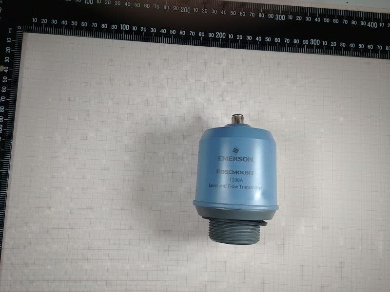
K8C1208CLB
May 09, 2023Level and Flow Transmitter
Equipment Class
LPR - Level Probing Radar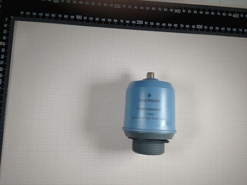
K8C1208LB
Dec 15, 2022Rosemount 1208A Level transmitter
Equipment Class
DTS - Digital Transmission System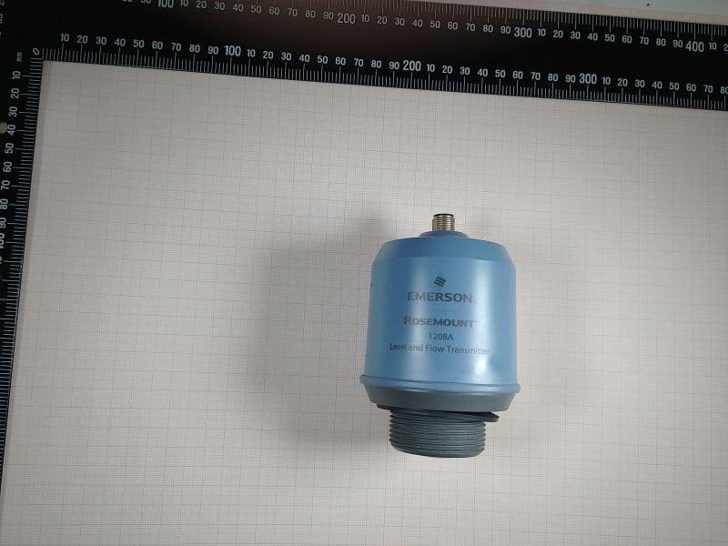
K8C1208L
Dec 15, 2022Rosemount 1208A Level transmitter
Equipment Class
LPR - Level Probing Radar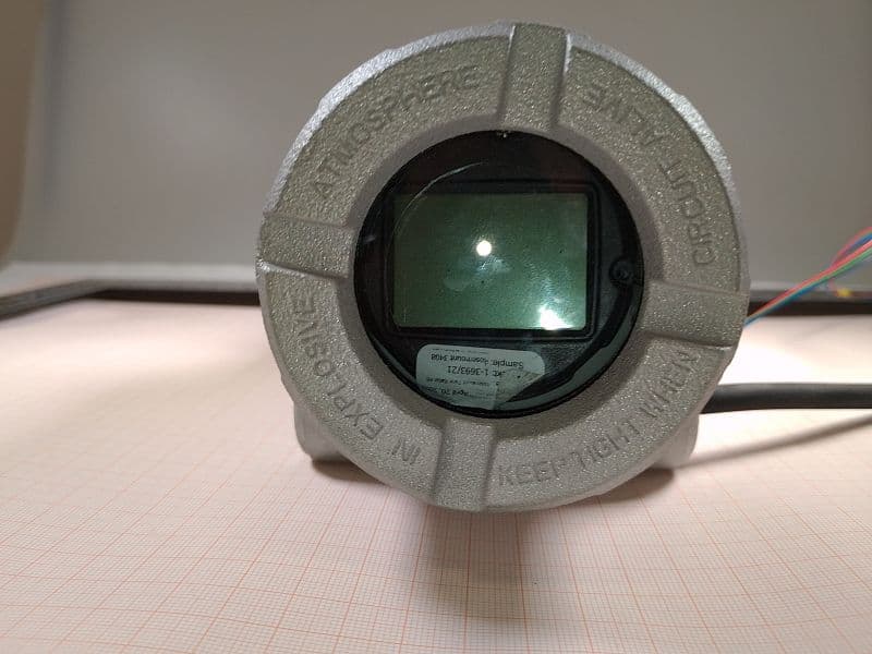
K8C3408T
Oct 20, 2022Rosemount 3408 Level Transmitter
Equipment Class
LPR - Level Probing Radar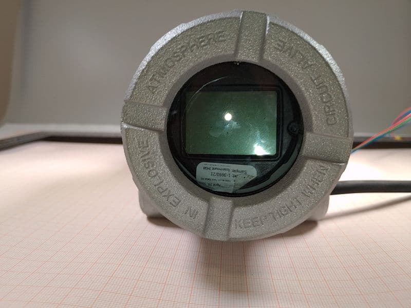
K8C3408TB
Oct 20, 2022Rosemount 3408 Level Transmitter
Equipment Class
LPR - Level Probing Radar