KCH-XEMICS-BATDTS/FHSS Transceiver
Sensus Metering Systems
Click to zoom
Application Details
- Equipment Class
- DTS - Digital Transmission System
- Date of Grant
- Dec 30, 2003
- Application Purpose
- Original Equipment
- Date of Application
- Dec 30, 2003
- Equipment Note
- DTS/FHSS Transceiver
- Frequency Range
- 908.40000000 - 923.20000000
- Company
- Sensus Metering Systems
- Country
- United States
Documents & Files
Document Text
Text extracted from the exhibit documents filed with the FCC. Open a document above to read the original.
Users Manual
Invensys Metering Systems Page 1 of 7 Invensys Metering Systems, ICG – Robert Shaw Radio Quick-Start Guide 8 October 2003 This document contains proprietary information. It may not be copied, transmitted or distributed, in whole or in part, without the consent of Invensys Metering Systems. Test Plan Invensys Metering Systems Page 2 of 7 Contents Contents..................................................................................................................... 2 1 INTRODUCTION.................................................................................................. 4 2 SETUP PROCEDURES ....................................................................................... 4 3 EXAMPLE ............................................................................................................ 5 REVISION SUMMARY date section change description 8 Oct 2003 Baseline document 9 Oct 2003 More screenshots and comments Test Plan Invensys Metering Systems Page 3 of 7 FCC Compliance NOTE: This equipment has been tested and found to comply with the limits for a Class B digital device, pursuant to part 15 of the FCC Rules. These limits are designed to provide reasonable protection against harmful interference in a residential installation. This equipment generates, uses and can radiate radio frequency energy and, if not installed and used in accordance with the instructions, may cause harmful interference to radio communications. However, there is no guarantee that interference will not occur in a particular installation. If this equipment does cause harmful interference to radio or television reception, which can be determined by turning the equipment off and on, the user is encouraged to try to correct the interference by one or more of the following measures; – Reorient or relocate the receiving antenna – Increase the separation between the equipment and receiver – Connect the equipment into an outlet on a circuit different from that to which the receiver is connected – Consult the dealer or an experienced radio/TV technician WARNING: No party shall make any modifications or changes to product circuitry without the express written consent of Invensys Metering Systems. Doing so could result in the equipment becoming non-compliant with the requirements of the Federal Communication Commission Rules CFR47 Part 15 and could void the user’s authority to operate the equipment. Note: To comply with FCC RF exposure requirements in section 1.1307, a minimum separation distance of 20 cm (8 inches) is required between the antenna and all persons. Test Plan Invensys Metering Systems Page 4 of 7 Introduction This document contains instructions for setting up communication between multiple Robert Shaw radios for testing purposes, and describes the use of the InvenStack test software. 1 Setup Procedures 1. Connect the radio to the RS232 interface/control board via the 10 pin connectors with a ribbon cable as shown in the photograph fig 1. Make sure that pin 1 on the interface board is connected to pin 1 on the radio (both are near the edge of the board). The interface board provides voltage level shifting between the PC and the radio board. 2. Connect the interface board to a PC via a standard RS232 cable. 3. Provide 3.3V DC (limit to 80mA per radio) to the interface board at the connections shown in the photograph fig 1. Current draw at 3.3V in on power-up should be about 30mA per radio. fig. 1 – Serial comm. and power connections 4. Start the InvenStack test application (start one for each radio) on the PC (screenshot fig. 2). Set up serial communication with the radio in the Com menu. 5. Set up the Filter Type, PanID and Local Address under the DLME tab. See fig. 2 below. Rese t Test Plan Invensys Metering Systems Page 5 of 7 fig 2. Setting up PanID and Local Address in DLME tab 6. Set up the log file if desired in the logging menu. 7. Under the FileMessages tab, browse to select individual files or batch files to run to begin sending messages between radios. Each file contains a command, the batch files can be used to loop or send consecutive commands with a user- determined delay between each. 2 Example The text below is from the message file DL_DATA_REQUEST_ACK_1.TXT. This will send a DL_DATA_request command. This will result in a DL_DATA_confirm from the InvenStack on the sending radio. This DL_DATA_confirm on the sending radio will indicate if the message was successfully transmitted. If AckMode is set to ACK_MONITORING (on) in the DL_DATA_request message, then a success in that confirm indicates that the RF ACK was received from the intended recipient of the message. The message contains the sample Lsdu data 01 02 03 04 05. All radios within range will receive the message. On all those with Filter Type NONE an Indication will result. On all those with Filter Type PAN ID, an Indication will result if the radios’ PanID matches that in the message (0x0001). On all those with Filter Type set to LOCAL ADDR, and Indication will result if the radios’ LocalAddress matches that in the message (0x02). On all those with Filter Type PAN AND LOCAL, an Indication will result only if both the PanID and LocalAddress of the radio matches the message. Regardless of the filter setting, an ACK will be generated by the receiving radio if and only if both the PanID and LocalAddress in Test Plan Invensys Metering Systems Page 6 of 7 the received message match those set in the receiving radio. The original sender will accept that ACK generated by the receiving radio if and only if the SrcPanID and SrcAddr in the original message are correct. Below are a few steps that can be followed to verify proper communication and a couple of screenshots that show the resulting messages in the test applications message windows. The file DL_DATA_REQUEST_ACK_1.TXT contains the following text. In the screenshot in fig. 3, this message has just been sent out and can be seen on the third line in the message window. / This is a te…
Text truncated - open the document above for the full version.
Cover Letter(s)
tel: 650-726-1263 fax: 650-726-1252 [email protected] Thomas N. Cokenias EMC &Radio Approvals Test & Consulting Services for Commercial, Military, International Compliance P.O. Box 1086 El Granada, CA 94018 email: [email protected] FCC Laboratory 8 October 2003 7435 Oakland Mills Road Columbia, MD 21046 Attention: Application Examiner Reviewing Engineer Re: Request for confidentiality per Section 0.459 of FCC Rules Applicant: Invensys Metering Systems FCC ID: KCH-XEMICS-BAT To whom it may concern, Request is hereby submitted, on behalf of my client, Invensys Metering Systems, to withhold from public review certain portions of the application for equipment certification for the referenced FCC identifier. In particular, the following sections of the application and report are requested to be kept confidential: Schematics Block Diagram Theory of Operations User manual Rationale for request for confidentiality: Invensys has invested considerable time and materials in research and development to produce the referenced product. Disclosure of the confidential portions of this application to competitors would give them competitive advantage in developing similar products. If you have questions or need further information, please contact the undersigned. Sincerely, THOMAS N. COKENIAS tel: 650-726-1263 fax: 650-726-1252 [email protected] EMC Consultant/Agent for Invensys
Cover Letter(s)
tel: 650-726-1263 fax: 650-726-1252 [email protected] Thomas N. Cokenias EMC &Radio Approvals Test & Consulting Services for Commercial, Military, International Compliance P.O. Box 1086 El Granada, CA 94018 email: [email protected] FCC Laboratory 8 October 2003 7435 Oakland Mills Road Columbia, MD 21046 Attention: Application Examiner Reviewing Engineer Re: Request for confidentiality per Section 0.459 of FCC Rules Applicant: Invensys Metering Systems FCC ID: KCH-XEMICS-BAT To whom it may concern, Request is hereby submitted, on behalf of my client, Invensys Metering Systems, to withhold from public review certain portions of the application for equipment certification for the referenced FCC identifier. In particular, the following sections of the application and report are requested to be kept confidential: Schematics Block Diagram Theory of Operations User manual Rationale for request for confidentiality: Invensys has invested considerable time and materials in research and development to produce the referenced product. Disclosure of the confidential portions of this application to competitors would give them competitive advantage in developing similar products. If you have questions or need further information, please contact the undersigned. Sincerely, THOMAS N. COKENIAS tel: 650-726-1263 fax: 650-726-1252 [email protected] EMC Consultant/Agent for Invensys
Cover Letter(s)
tel: 650-726-1263 fax: 650-726-1252 [email protected] Thomas N. CokeniasEMC &Radio Approvals Test & Consulting Services for Commercial, Military, International Compliance P.O. Box 1086 El Granada, CA 94018email: [email protected] Compliance Certification Services 561F Monterey Road Morgan Hill, CA 95037 Attention: Mike Kuo Re: Limited Modular approval for Part 15 DTS Product Applicant: Invensys Metering Systems FCC ID: KCH-XEMICS-BAT Dear Mike, Invensys has developed a 902-928 MHz DTS product for which they are seeking limited modular approval. The transceiver board will be used in a variety of products manufactured by Invensys, such as utility meters, thermostats, and energy management systems. The referenced device is a single board product with a permanently attached printed circuit board antenna. It can be configured as a narrowband frequency hopping transceiver using 50 – 140 kHz hopping channels, or it can be configured as a wideband DTS system using four channels, each approximately 600 kHz wide. A hopping mode is available for wideband operation. Maximum output power is 13 dBm nominal. FCC Public Notice DA00-1407, released June 26, 2000, contains the equipment authorization requirements for a modular or limited modular certification. Eight basic requirements are called out. Relevance to the Invensys product with respect to each requirement are as follows: 1. The mo dular transmitter mus t hav e its o w n RF s hielding. The Invensys product referenced above (hereafter the EUT) has its own shield can. Tests show the EUT requires no additional shielding to meet radiated emissions. 2. The modular transmitter mus t have buffered modulation/data inputs The EUT does not have buffered data inputs. Invensys will control the designs of the products in which the EUT will be incorporated and as such will be able to insure that data rates and voltage levels will not result in undesired operation and will continue to adhere to Part 15 requirements. 3. The modular transmitter mus t have its ow n pow er s upply regulation. The EUT does not have its own power supply regulation. Invensys will control the designs of the products in which the EUT will be incorporated and as such will be able to insure that DC power input levels will not result in undesired operation and will continue to adhere to Part 15 requirements. tel: 650-726-1263 fax: 650-726-1252 [email protected] 4. The mo dular transmitter mus t co mply w ith the antenna requirements o f Section 15.203 and 15. 204(c). The EUT has a printed circuit board antenna and complies with this requirement. 5. The mo dular transmitter mus t be tes ted i n a s tand-alone configuration, i. e. , the module must not be ins ide another device during testing. The EUT was tested stand alone and meets this requirement. 6. The mo dular transmitter mus t be labeled w ith its ow n FCC ID number, and, if the FCC ID is not vis ible when the module is installed inside ano ther dev ice, then the o uts ide o f the dev ice into w hich the mo dule is installed must also display a label referring to the enclosed module.. The EUT has its own FCC ID label. For those products that will incorporate the EUT, invensys will place an additional label for products that obscure a clear view of the EUT FCC ID label. 7. The mo dular transmitter mus t co mply w ith any s pecif ic rule o r o perating re quire ments applicable to the transmitter and the manufacturer mus t provide adequate ins tructions along w ith the module to explain any s uch re quirements. User instru c t i o n s will be submitted with the EUT application for certification. 8. The mo dular transmitter mus t co mply w ith any applicable RF ex po sure re quirements. The EUT meets MPE limits at a calculated 3. 5 cm separation distance. Invensys will have control over the future designs of products that will use the referenced modular transceiver. As such, Invensys will be in the position to insure that operating parameters will be within the limits that will maintain compliance with all Part 15 requirements. A copy of this letter has been submitted to Invensys Metering Systems. If you have questions or need further information, please contact the undersigned. Sincerely, T. N. Cokenias Agent for Invensys tel: 650-726-1263 fax: 650-726-1252 [email protected]
Cover Letter(s)
1 Chris Harvey From:Tom Cokenias [[email protected]] Sent:Monday, December 29, 2003 12:46 PM To:Chris Harvey Subject:Re: Invensys application AN01T3340 FCC ID: KCH-XEMICS-BAT Limited_Modular_let ter.pdf (26... XEMICS_label.pdf (54 KB) Xemics_29Dec_RPT COR.pdf (856 K... Hi Chris, Attached please find the letter, label, and corrected report. The report now has a section III referencing acceptable test procedures, and the radiated test procedure correctly describes the different orientations into which the EUT was placed for testing. I will upload these documents to the CCS website as well. Please let me know by return if there is anything else you need. I have a class 2 permissive change application waiting to be submitted for this product. Best regards Tom >Tom, the above referenced application has been reviewed for both >technical and administrative content. The following items need to be >addressed so that continued review of this application can be >completed. > >This application is apparently being filed for Limited Modular Approval >(LMA). A document has been submitted that has a file name that implies >an LMA filing, but the content of the letter does not specificlly >request LMA approval. If this LMA is being requested, please revise >the letter to request LMA approval, ensuring that the FCC ID number of >the application is included and ensuring that all 8 requirements for >LMA are addressed. > >Please provide a sample FCC ID label and label location diagram. If >this is an LMA approval, please ensure that the LMA labeling >requirements are also addressed. > >The photographs of test setups implies that the EUT was tested in 3 >orthogonal axis, however the test report does not mention the >orientation beyond being vertical. Please correct the report if the >unit was in fact reoriented as in the photographs. > >The test procedure used for these test is not specified in the test >report. Please state the test procedure used, ensuring that it is an >acceptable test procedure for FCC compliance. > >Best regards, 2 > >Chris Harvey >[email protected] > >The items indicated above must be submitted before processing can >continue on the above referenced application. Failure to provide the >requested information within 30 days of the original e-mail date may >result in application dismissal and forfeiture of the filing fee. Also, >please note that partial responses increase processing time and should >not be submitted. Any questions about the content of this >correspondence should be directed to the e-mail address listed below >the name of the sender.
External Photos
Invensys FCC ID: KCH-XEMICS-BAT Product Photographs Invensys FCC ID: KCH-XEMICS-BAT Invensys FCC ID: KCH-XEMICS-BAT Invensys FCC ID: KCH-XEMICS-BAT Invensys FCC ID: KCH-XEMICS-BAT
External Photos
Invensys FCC ID: KCH-XEMICS-BAT Product Photographs Invensys FCC ID: KCH-XEMICS-BAT Invensys FCC ID: KCH-XEMICS-BAT Invensys FCC ID: KCH-XEMICS-BAT Invensys FCC ID: KCH-XEMICS-BAT
ID Label/Location Info
Invensys FCC ID: KCH-XEMICS-BAT FCC Label and Label Location Invensys FCC ID: KCH-XEMICS-BAT Label will be attached in blank area on foil side of EUT: FCC ID: KCH-XEMICS-BAT This device complies with Part 15 of FCC Rules. Operation is subject to the following two conditions: (1) This device may not cause harmful interference, and (2) this device must accept any interference received, including interference that may cause undesired operation.
Internal Photos
Invensys FCC ID: KCH-XEMICS-BAT Product Photographs Invensys FCC ID: KCH-XEMICS-BAT Invensys FCC ID: KCH-XEMICS-BAT Invensys FCC ID: KCH-XEMICS-BAT Invensys FCC ID: KCH-XEMICS-BAT
Test Report
FCC ID: KCH-XEMICS-BAT Invensys XEMICS module 1 of 37 900MHz DTS/FHSS Hybrid EMISSIONS TEST REPORT FOR A LOW POWER TRANSMITTER I. GENERAL INFORMATION Requirement:Federal Communications Commissions Industry Canada Test Requirements: 15.205, 15.207, 15.209, 15.247 RSS-210 Applicant: Invensys Metering Systems FCC ID: KCH-XEMICS-BAT II. DESCRIPTION OF EQUIPMENT UNDER TEST (EUT) The Invensys FCC ID: KCH-XEMICS-BAT is a limited modular hybrid FHSS/DTS transceiver operating at 902-928 MHz, used with Invensys power meters and other energy management products. Transmitter Specification Supply Voltage2.4v – 3.6v Current69mA TX Power13dBm (nom.) Frequency Deviation (FSK)+/- 40 kHz (narrow band) +/- 250 kHz (wide band) Centre Frequency Error+15 / -25 kHz Frequency of operation905.2 – 924.8 MHz Data Rate19.2 kbps Data FormatNRZ Number of channels (see hop tables)50 (narrow band) 4 (wide band) Channel Separation400 kHz (narrow band) 5 MHz (wide band) 20dB occupied bandwidth130 kHz (narrow band) 620 kHz (wide band) 6dB occupied bandwidth550 kHz (wide band) Temperature Range-40°C to +85°C FCC ID: KCH-XEMICS-BAT Invensys XEMICS module 2 of 37 900MHz DTS/FHSS Hybrid III . TEST PROCEDURE REFERENCE Testing was performed in accordance to the requirements of the following published test procedures /standards, unless otherwise indicated: ANSI C63.4Radiated emissions, 30 – 40,000 MHz AC line conducted emissions, 0.150 – 30 MHz FCC Public Notice 97-114Guidance on Measurements for Direct Sequence Spread Spectrum Systems FCC Public Notice DA00-705Filing and Measurement Guidelines for Frequency Hopping Spread Spectrum Systems IV. TEST LOCATION All tests except channel occupancy tests were performed at Compliance Certification Services 561F Monterey Road Morgan Hill, CA 95037 Channel occupancy tests were performed by Invensys Metering Systems. T.N. Cokenias8 October 2003 EMC Consultant/Agent for Invensys FCC ID: KCH-XEMICS-BAT Invensys XEMICS module 3 of 37 900MHz DTS/FHSS Hybrid 15.203 Antenna connector requirement The antenna is permanently attached to the product. Antenna gain figures are found in Operational Description (separate attachment). Maximum peak antenna gain is 5.6 dBi. 15.204 Antenna description The transceiver module uses a printed circuit board antenna. Measured antenna data and radiation patterns are presented in Operational Description (separate attachment). Maximum peak antenna gain is 5.6 dBi 15.247(a) Frequency hopping spread spectrum definition Pseudorandom frequency hopping sequence: The transmitter cannot coordinate its hopping sequence with the hopping sequence of other transmitters, or vice versa, for the purpose of avoiding the simultaneous occupancy of individual hopping frequencies by multiple transmitters Each access unit has an individual ID number and there is no link or association between two access units so there is no simultaneous occupancy of individual hopping frequency transmission of two or more access units. Equal hopping frequency use: The EUT utilizes 50 hopping channels. Hopset is 50 channels long, then repeats. On average all channels are used equally. System receiver input bandwidth and receiver hopping capability: Receiver 26 dB bandwidth is 200 kHz, approximately equal to 26 dB bandwidth of TX. Receiver channel hops are synchronized to transmitter operating frequency. 15.247(f) Hybrid Systems Wideband Mode In addition to frequency hopping operation, the EUT has a wideband DTS mode. Each channel is approximately 550 kHz wide. The wideband channels hop in such a way that maximum channel occupancy is approximately 200 msec in any 20 second period. Power spectral density is less than 8 dBm/3kHz. FCC ID: KCH-XEMICS-BAT Invensys XEMICS module 4 of 37 900MHz DTS/FHSS Hybrid TEST DATA and TEST PROCEDURES - CCS Laboratory Radiated Emissions Test Requirement: 15.205, 15.247 Out of Band Measurements Test Requirement: 15.247 Measurement Equipment Used: Agilent E4446A Spectrum analyzer Miteq NSP2600-44 Microwave pre-amplifier, 1-26.5 GHz EMCO 3115 Double Ridged Horn antenna, 1 - 18 GHz Radiated emissions generated by the transmitter portion of the EUT were measured. 1. The EUT was placed on a wooden table resting on a turntable in the anechoic chamber. The EUT was configured in the “X” orientation as shown in attached test setup photographs. The search antenna was placed 3m from the EUT. 2. The turntable was slowly rotated to locate the direction of maximum emission at each emission falling in the restricted bands of 15.205. 3. Radiated emissions were investigated for a LOW channel, a MID channel, and HIGH channel. Emissions were investigated to the 10 th harmonic. 4. Once maximum direction was determined, the search antenna was raised and lowered in both vertical and horizontal polarizations. 5. Steps (2) through (4) above were repeated with the EUT in the “Y” and “Z” orientations. The maximum readings so obtained are recorded in the data listed below. Test Results: Worst case results are presented. Refer to data sheets in separate attachments. Restricted band emissions meet 54 dBuV/m. Other undesired emissions from the transmitter meet the -20 dBc requirement in 15.247(c). FCC ID: KCH-XEMICS-BAT Invensys XEMICS module 5 of 37 900MHz DTS/FHSS Hybrid Radiated Emissions Test Requirement: 15.109 Measurement Equipment Used: HP 8542E EMI Receiver, 9kHz-2.9 GHz Schaffner/Chase CBL6112B Bilog Antenna, 30 - 2000 MHz Radiated emissions below 1 GHz and those generated by the digital portion of the EUT were measured. 1. The EUT was placed on a wooden table resting on a turntable in the anechoic chamber. The search antenna was placed 3m from the EUT. The EUT antenna was mounted vertically as per normal installation. The EUT was set to transmit continuously . 2. Measurement software was activated and results plotted. Test Results: Worst case results are presented. Refer to data sheets in separate attachment. NOTE: Data sheets show two frequencies over FCC class B limit: 934.040 MHz – This is …
Text truncated - open the document above for the full version.
Test Setup Photos
Invensys FCC ID: KCH-XEMICS-BAT Test Set-up Photographs Invensys FCC ID: KCH-XEMICS-BAT AC Line conducted using laboratory AC/DC power supply Invensys FCC ID: KCH-XEMICS-BAT AC line conducted Invensys FCC ID: KCH-XEMICS-BAT Radiated emissions below 1 GHz Invensys FCC ID: KCH-XEMICS-BAT Radiated emissions above 1 GHz Invensys FCC ID: KCH-XEMICS-BAT X orientation Invensys FCC ID: KCH-XEMICS-BAT Y orientation Invensys FCC ID: KCH-XEMICS-BAT Z orientation
Contact Information
Applicant
Richard Daniel(Director, Engineering NPI and Project Management)
Test Firm
Compliance Certification Services IncSteve Cheng
Technical Specifications
| # | Rule Parts | Frequency Range | Power Output |
|---|---|---|---|
| 2 | 15C | 908.4 MHz - 923.2 MHz | 25.00 mW |
Other Applications from Sensus Metering Systems
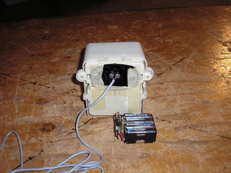
KCH510R2
Nov 13, 2006Utility Meter Transceiver
Equipment Class
DTS - Digital Transmission System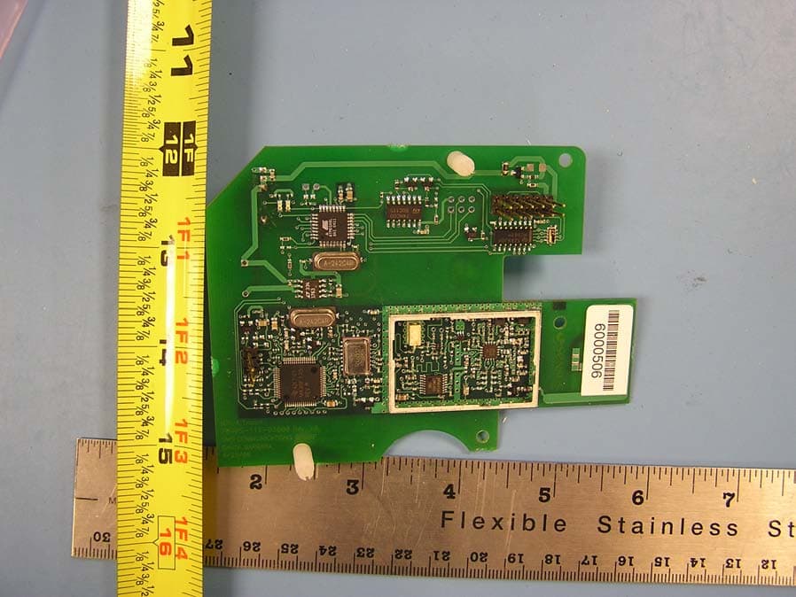
KCHMXU530T
Aug 22, 2006Radio Transceiver for Electric Meter
Equipment Class
DTS - Digital Transmission System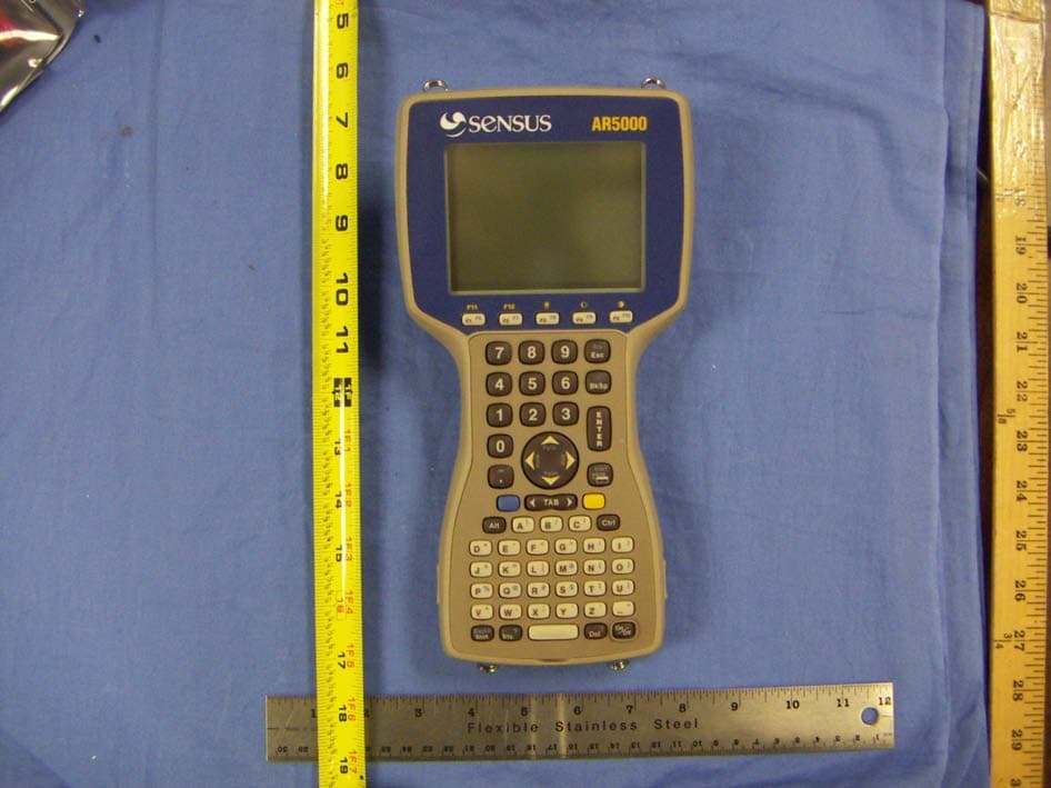
KCHAR5002
Jun 13, 2006Utility Meter RF Transceiver
Equipment Class
DXT - Part 15 Low Power Transceiver, Rx Verified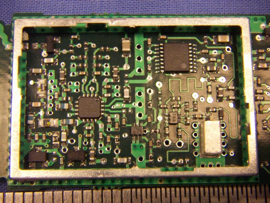
KCH520R
Jun 28, 2005900MHz DTS RF Module
Equipment Class
DTS - Digital Transmission System
KCHGS0003
Jan 19, 2005AUTOMATIC GAS METER TRANSMITTER
Equipment Class
DTS - Digital Transmission System