KCH520CTransmitter for Utility Meter
Sensus Metering Systems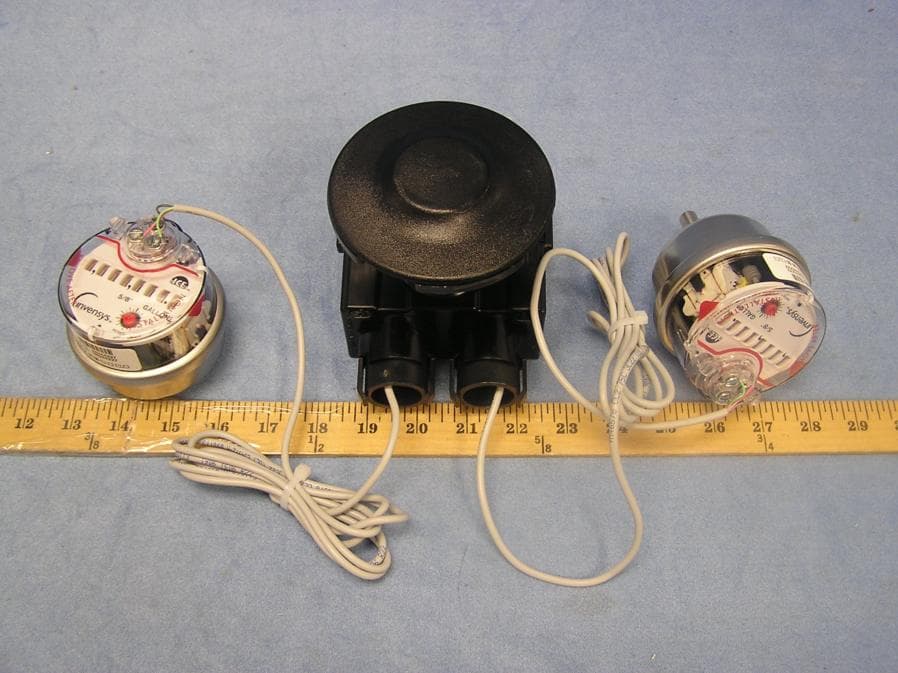
Click to zoom
Application Details
- Equipment Class
- DTS - Digital Transmission System
- Date of Grant
- Nov 28, 2004
- Application Purpose
- Original Equipment
- Date of Application
- Nov 28, 2004
- Equipment Note
- Transmitter for Utility Meter
- Frequency Range
- 903.80000000 - 926.20000000
- Company
- Sensus Metering Systems
- Country
- United States
Documents & Files
Document Text
Text extracted from the exhibit documents filed with the FCC. Open a document above to read the original.
Users Manual
Model 520C User’s Guide Revision 1.0, 13 September, 2004 Sensus Metering Systems-North America Inc. This document contains proprietary information. It may not be copied, transmitted or distributed, in whole or in part, without the consent of Sensus Metering Systems-North America Inc. Sensus Metering Systems-North America Inc. CellNet Water MTU User’s Guide 1 REVISION SUMMARY Date Author Change Description 12 August, 2004 GM/CP/AN Baseline 13 September, 2004 GM Removed references to Register wiring. Cleanup. Sensus Metering Systems-North America Inc. CellNet Water MTU User’s Guide 2 TABLE OF CONTENTS 1. INTRODUCTION......................................................................................................................................3 1.1 REFERENCE DOCUMENTS.....................................................................................................................3 1.2 OPEN ISSUES........................................................................................................................................3 1.3 GLOSSARY...........................................................................................................................................4 2. CELLNET WATER MTU OVERVIEW..................................................................................................5 2.1 FEATURES............................................................................................................................................5 2.1.1 Field Configurable.....................................................................................................................................5 2.1.2 Magnetic Switch Controlled Activation/Deactivation...............................................................................5 2.1.3 Magnetic Switch Forced Transmission......................................................................................................5 2.1.4 Touch Coupled Register Interface.............................................................................................................5 2.1.5 Battery Life................................................................................................................................................5 2.1.6 FCC...........................................................................................................................................................6 2.2 FUNCTIONAL DESCRIPTION..................................................................................................................7 2.2.1 Overview...................................................................................................................................................7 2.2.2 Description................................................................................................................................................7 2.2.2.1 Installing the Endpoint.........................................................................................................................7 2.2.2.2 Activation...........................................................................................................................................12 2.2.2.3 Operation............................................................................................................................................15 2.2.2.4 Diagnostics.........................................................................................................................................16 2.2.2.5 Forcing a Meter Read.........................................................................................................................16 2.2.2.6 Deactivation.......................................................................................................................................16 2.2.3 Summary..................................................................................................................................................18 2.3 CONFIGURATION................................................................................................................................19 2.3.1 Configuration as Shipped........................................................................................................................19 2.3.2 Supported Encoders.................................................................................................................................20 2.3.3 Re-Configuring In the Field....................................................................................................................20 Sensus Metering Systems-North America Inc. CellNet Water MTU User’s Guide 3 1. Introduction This document describes how to install, activate, operate and deactivate the CellNet Meter Transponder Unit (MTU). 1.1 Reference Documents The following documents are referenced by this document: [1] RF LAN1 Air Interface Specification (95-1501Rev. A), CellNet, 5 May 2004 [2] Preliminary – Protocol Data Unit Specification, PID 0x02, 0x03, 0x04 – Electric, Gas and Water Meter Packets Rev. C, CellNet, 5 May 2004 1.2 Open Issues • Sensus Metering Systems-North America Inc. CellNet Water MTU User’s Guide 4 1.3 Glossary BPSK Binary Phase Shift Keying CRC Cyclic Redundancy Check ECR Electronically Controlled Register FCC Federal Communications Commission JEA Jacksonville Electric Authority kHz Kilohertz LAN Local Area Network LED Light Emitting Diode MHz Megahertz MTU Meter Transmitter Unit OOK On-Off Keying RAD-40 CellNet proprietary compression scheme RF Radio Frequency TRPL Touch Read Pit-Lid TX Transmit Sensus Metering Systems-North America Inc. CellNet Water MTU User’s Guide 5 2. CellNet Water MTU Overview The sections which follow provide a high-level functional description of the CellNet Water MTU. 2.1 Features The CellNet Water MTU provides the following features: 2.1.1 Field Configurable The CellNet Water MTU can be configured via the programming interface using the Touch Gun. Configurable par…
Text truncated - open the document above for the full version.
Cover Letter(s)
tel: 650-726-1263 fax: 650-726-1252 [email protected] Thomas N. Cokenias EMC &Radio Approvals Test & Consulting Services for Commercial, Military, International Compliance P.O. Box 1086 El Granada, CA 94018 email: [email protected] Compliance Certification Services 31 October 2004 561F Monterey Road Morgan Hill CA 95037 Attention: Mike Kuo Re: Request for confidentiality per Section 0.459 of FCC Rules Applicant: Sensus Metering Systems FCC ID: KCH520C Dear Mike, Request is hereby submitted, on behalf of my client, Sensus Metering Systems, to withhold from public review certain portions of the application for equipment certification for the referenced FCC identifier. In particular, the following sections of the application and report are requested to be kept confidential: Schematics Block Diagram Theory of Operations Rationale for request for confidentiality: Sensus has invested considerable time and materials in research and development to produce the referenced product. Disclosure of the confidential portions of this application to competitors would give them competitive advantage in developing similar products. If you have questions or need further information, please contact the undersigned. Sincerely, THOMAS N. COKENIAS EMC Consultant/Agent for Sensus Metering Systems tel: 650-726-1263 fax: 650-726-1252 [email protected]
Cover Letter(s)
1 Mike Kuo From: Chris Harvey [[email protected]] Sent: November162004Tuesday 10:52 AM To: Mike Kuo Subject: FW: Sensus Metering Systems, FCC ID: KCH520C, Assessment NO.: AN04T4300, Notice#1 FYI... -----Original Message----- From: Compliance Certification Services [mailto:[email protected]] Sent: Tuesday, November 16, 2004 6:30 PM To: [email protected] Cc: [email protected] Subject: Sensus Metering Systems, FCC ID: KCH520C, Assessment NO.: AN04T4300, Notice#1 Tom, I have reviewed the above referenced application and find that the following items need to be addressed in order to complete the review: 1. Please provide a label location drawing/photo. 2. The Frequency Range is at set channels 911.58, 914.58, 917.58 MHz per manual but 903.8-926.2 MHz from report. Please clarify this discrepancy. 3. Please provide a clear indication of the test procedures used for the measurements in the test report. Best regards, Chris Harvey [email protected] The items indicated above must be submitted before processing can continue on the above referenced application. Failure to provide the requested information within 30 days of the original e-mail date may result in application dismissal and forfeiture of the filing fee. Also, please note that partial responses increase processing time and should not be submitted. Any questions about the content of this correspondence should be directed to the e-mail address listed below the name of the sender.
External Photos
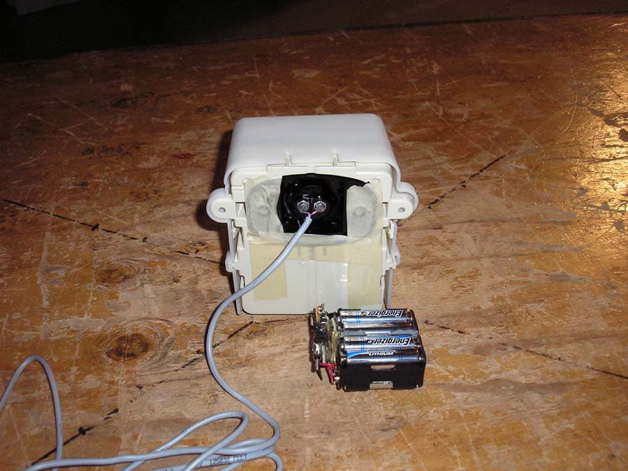
FCC ID: KCH520C External Photographs FCC ID: KCH520C FCC ID: KCH520C FCC ID: KCH520C FCC ID: KCH520C
ID Label/Location Info
FCC ID: KCH520C FCC ID: KCH520C FCC ID label area
Test Report
FCC ID: KCH520C Sensus 520C Meter Transmitter Unit 1 of 45 900MHz DTS EMISSIONS TEST REPORT FOR A LOW POWER TRANSMITTER I. GENERAL INFORMATION Requirement:Federal Communications Commissions Test Requirements: 15.205, 15.207, 15.209, 15.247 Applicant:Sensus Metering Systems FCC ID:!!KCH520C II. DESCRIPTION OF EQUIPMENT UNDER TEST (EUT) The Sensus FCC ID: KCH520C is a digital transmission system (DTS) operating under the requirements in FCC Part 15. The product is a water meter , part of a Cellnet network that transmits meter readings to a neighborhood hub/access point r unit owned by the utility. The transmitter sends short bursts of data as required by the network, as little as once every 84 hours, as often as once every 15 seconds. The transmit times are pre- programmed and stored in the product’s EEPROM. A lithium battery powers the EUT, the battery has an expected life of over 15 years. The 520C operates in the U.S. ISM band between 902 and 928 MHz. Transmitter Specification TX Power27.56 dBm max. Frequency of operation903.8-926.2 MHz Data Rate19.2656 Kbps in <25ms burst 6 dB bandwidth1.15 MHz Power sourcelithium battery III. TEST DATES AND TEST LOCATION Testing was performed 20-21 October 2004. All tests were performed at: Compliance Certification Services 561F Monterey Road Morgan Hill, CA 95037 T.N. Cokenias29 October 2004 EMC Consultant/Agent for Sensus Metering Systems FCC ID: KCH520C Sensus 520C Meter Transmitter Unit 2 of 45 900MHz DTS 15.203 Antenna connector requirement The antenna is permanently attached to the product. For antenna conducted tests, a unit was modified by disconnecting the printed circuit antenna and replacing it with a 50 ohm coaxial cable connection terminated at one end with an SMA connector. 15.204 Antenna description The meter transceiver uses a printed circuit folded dipole antenna: Antenna descriptionGain printed ckt antenna2.2 dBi TEST DATA and TEST PROCEDURES - CCS Laboratory Radiated Emissions Test Requirement: 15.205, 15.247 Out of Band Measurements Test Requirement: 15.247 Measurement Equipment Used: Agilent 4440A Spectrum Analyzer, 9 kHz-26.5 GHz Chase Biconolog antenna EMCO 3115 Horn antenna, 1-18 GHZ Miteq pre-amplifier, 1 – 26.5 GHz IFI High pass filter, fp = 1800 MHz Radiated emissions generated by the transmitter portion of the EUT were measured. 1. The EUT was placed on a wooden table resting on a turntable on the test site. Two water meters were connected to the appropriate ports as typical loads. The search antenna was placed 3m from the EUT. The EUT antenna was mounted vertically as per normal installation. 2. The turntable was slowly rotated to locate the direction of maximum emission at each emission falling in the restricted bands of 15.205. 3. Radiated emissions were investigated for a LOW channel, a MID channel, and HIGH channel. Emissions were investigated to the 10 th harmonic. 4. Once maximum direction was determined, the search antenna was raised and lowered in both vertical and horizontal polarizations. The maximum readings so obtained are recorded in the data listed below. Test Results: Worst case results are presented. Refer to data sheets below. Restricted band emissions meet 54 dBuV/m. Other undesired emissions from the transmitter meet the -20 dBc requirement in 15.247(c). FCC ID: KCH520C Sensus 520C Meter Transmitter Unit 3 of 45 900MHz DTS FCC Radiated Emissions Limits Section 15.205 Restricted bands of operation. (a) Except as shown in paragraph (d) of this section, only spurious emissions are permitted in any of the frequency bands listed below: MHzMHzMHzGHz 0.090 - 0.110 0.495 - 0.505 (1) 2.1735 - 2.1905 4.125 - 4.128 4.17725 - 4.17775 4.20725 - 4.20775 6.215 - 6.218 6.26775 - 6.26825 6.31175 - 6.31225 8.291 - 8.294 8.362 - 8.366 8.37625 - 8.38675 8.41425 - 8.41475 12.29 - 12.293 12.51975 - 12.52025 12.57675 - 12.57725 13.36 - 13.41 16.42 - 16.423 16.69475 - 16.69525 16.80425 - 16.80475 25.5 - 25.67 37.5 - 38.25 73 - 74.6 74.8 - 75.2 108 - 121.94 123 - 138 149.9 - 150.05 156.52475 - 156.52525 156.7 - 156.9 162.0125 - 167.17 167.72 - 173.2 240 - 285 322 - 335.4 399.9 - 410 608 - 614 960 - 1240 1300 - 1427 1435 - 1626.5 1645.5 - 1646.5 1660 - 1710 1718.8 - 1722.2 2200 - 2300 2310 - 2390 2483.5 - 2500 2655 - 2900 3260 - 3267 3332 - 3339 3345.8 - 3358 3600 - 4400 4.5 - 5.15 5.35 - 5.46 7.25 - 7.75 8.025 - 8.5 9.0 - 9.2 9.3 - 9.5 10.6 - 12.7 13.25 - 13.4 14.47 - 14.5 15.35 - 16.2 17.7 - 21.4 22.01 - 23.12 23.6 - 24.0 31.2 - 31.8 36.43 - 36.5 (2) 1 Until February 1, 1999, this restricted band shall be 0.490-0.510 MHz. 2 Above 38.6 (b) Except as provided in paragraphs (d) and (e), the field strength of emissions appearing within these frequency bands shall not exceed the limits shown in Section 15.209. At frequencies equal to or less than 1000 MHz, compliance with the limits in Section 15.209 shall be demonstrated using measurement instrumentation employing a CISPR quasi-peak detector. Above 1000 MHz, compliance with the emission limits in Section 15.209 shall be demonstrated based on the average value of the measured emissions. The provisions in Section 15.35 apply to these measurements. (c) Except as provided in paragraphs (d) and (e), regardless of the field strength limits specified elsewhere in this Subpart, the provisions of this Section apply to emissions from any intentional radiator. Section 15.209 Radiated emission limits, general requirements. (a) Except as provided elsewhere in this Subpart, the emissions from an intentional radiator shall not exceed the field strength levels specified in the following table: Frequency Field Strength Measurement Distance (MHz) (microvolts/meter) (meters) _______________________________________________________________ 0.009 - 0.490 2400/F(kHz) 300 0.490 - 1.705 24000/F(kHz) 30 1.705 - 30.0 30 30 30 - 88 100 ** 3 88 - 216 150 ** 3 216 - 960 200 ** 3 Above 960 500 3 _______________________________________________________________ FCC ID: KCH520C Sensus 520C Meter Transmitter Unit 4 o…
Text truncated - open the document above for the full version.
Test Report
FCC ID: KCH520C ADDENDUM TO CERTIFICATION TEST REPORT Applicant: Sensus Metering Systems Description of Product: 902 – 928 MHz DTS Transceiver for Utility Meter FCC ID: KCH520C TEST PROCEDURES For tests performed on the referenced device in test report dated 29 October 2004, all testing was done in accordance with the applicable procedures called out in the following documents, unless otherwise noted: 1) ANSI C63.4 – 2003, American National Standard for Methods of Measurement of Radio-Noise Emissions from Low-Voltage Electrical and Electronic Equipment in the Range of 9 kHz to 40 GHz 2) FCC Public Notice 97-114, Guidance on Measurements for Direct Sequence Spread Spectrum SystemsIN ordance with the applicable procedures called out in the following documents, unless otherwise noted:
Test Setup Photos
FCC ID: KCH520C Test Setup Photographs FCC ID: KCH520C FCC ID: KCH520C FCC ID: KCH520C
Contact Information
Applicant
Richard Daniel(Director, Engineering NPI and Project Management)
Test Firm
Compliance Certification Services IncSteve Cheng
Technical Specifications
| # | Rule Parts | Frequency Range | Power Output |
|---|---|---|---|
| 1 | 15C | 903.8 MHz - 926.2 MHz | 570.00 mW |
Other Applications from Sensus Metering Systems
KCH510R2
Nov 13, 2006Utility Meter Transceiver
Equipment Class
DTS - Digital Transmission System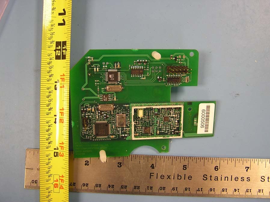
KCHMXU530T
Aug 22, 2006Radio Transceiver for Electric Meter
Equipment Class
DTS - Digital Transmission System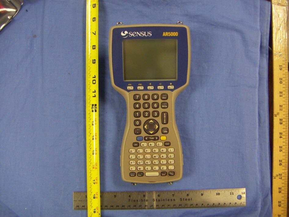
KCHAR5002
Jun 13, 2006Utility Meter RF Transceiver
Equipment Class
DXT - Part 15 Low Power Transceiver, Rx Verified
KCH520R
Jun 28, 2005900MHz DTS RF Module
Equipment Class
DTS - Digital Transmission System
KCHGS0003
Jan 19, 2005AUTOMATIC GAS METER TRANSMITTER
Equipment Class
DTS - Digital Transmission System