KCHBA0031Network Base Station For Metering System
Sensus Metering Systems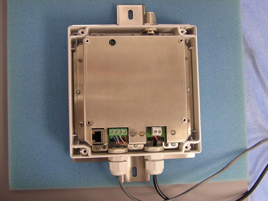
Click to zoom
Application Details
- Equipment Class
- DTS - Digital Transmission System
- Date of Grant
- Dec 13, 2004
- Application Purpose
- Original Equipment
- Date of Application
- Dec 13, 2004
- Equipment Note
- Network Base Station For Metering System
- Frequency Range
- 904.60000000 - 925.40000000
- Company
- Sensus Metering Systems
- Country
- United States
Documents & Files
Document Text
Text extracted from the exhibit documents filed with the FCC. Open a document above to read the original.
Users Manual
Network Base Station BA0031-A User Manual BA0031 User Manual (12.14.04) Page 2 12/14/2004 Table of Contents FCC Warning................................................................................................................3 General..........................................................................................................................4 Installation......................................................................................................................4 Installation Steps.........................................................................................................4 Software Package Installation......................................................................................4 Device Configuration...................................................................................................5 Device Mode Setting...............................................................................................5 Device Mode – NTR (BA0031-I & BA0031-E models).........................................7 Device Mode – NBS (all models)............................................................................8 RF Parameters Setting.............................................................................................9 Subscriber List Setting (NTR mode, BA0031-I & BA0031-E models)..................10 BA0031 User Manual (12.14.04) Page 3 12/14/2004 FCC Warning FCC Warning Modifications not expressly approved by the manufacturer could void the user authority to operate the equipment under FCC Rules. To comply with FCC RF Exposure requirements, the antenna(s) used for this transmitter must be fixed-mounted on outdoor permanent structures with a separation distance of at least 2 meters from all persons and must not be co-located or operating in conjunction with any other antenna or transmitter. Installation of BA0031 NTR: Installation of Model BA0031 and associated antennae (internal and external) must be performed by trained professionals only. The following antennae (or equivalent) should be used for the various BA0031 models. BA0031-I: Antenna Model – Internal Patch (Sensus Drawing Number 7300574), (4dBi) BA0031-E: Amphenol Antel BCD-8243 (5.15dBi Omni) BA0031-R: Amphenol Antel BCD-87066 (8.15dBi Omni) BA0031 User Manual (12.14.04) Page 4 12/14/2004 General This document describes the installation of the Network Base Station (NBS) / Network Repeater (NTR). The device has 3 different models: • BA0031-I – Two-way device with internal antenna. Works as NBS or NTR. • BA0031-E – Two-way device with connector for external antenna. Works with Antel’s BCD-8243, 3dBd omni antenna (ONLY). Works as NBS or NTR. • BA0031-R – Receive only device with connector for external antenna. Antenna type is not restricted. Works as ‘receive only’ NBS. Does not support NTR mode. Installation Installation Steps 1. Install the supplied ‘LabVIEW’ Run-Time engine and the configuration program ‘Base II v1.12’ in your PC by following the procedure described in Software Package Installation. 2. Disassemble the device top cover. 3. Insert the Ethernet backbone communication cable (not supplied, used in Base Station mode only) and the output cord of the 115VAC to 9VAC transformer (supplied) via the cable entries and connect them. 4. Plug the transformer to 115VAC source. 5. Use the serial communication cable (supplied) to connect available COM port on your PC to the device Console Port (RJ45 connector). 6. Configure the device by following the procedure described in Device Configuration 7. Disconnect the serial communication cable and assemble the top cover. 8. Mount the device and connect to external antenna if applicable. Software Package Installation 1. Insert the supplied CD-ROM. Open the folder ‘LabVIEW Run-Time’ and double click on ‘lvrteinstall.exe’. Next, follow the instructions of the installation program. 2. Create new folder on your PC and copy the file ‘Base II v1.12.exe’ from the supplied CD-ROM to the new folder. 3. Double click the file to run the program ‘Base II v1.12’. BA0031 User Manual (12.14.04) Page 5 12/14/2004 Device Configuration Device Mode Setting 1. Run the ‘Base II v1.12’ program. 2. Select ‘General’ tab. 3. Set to proper PC COMM port. BA0031 User Manual (12.14.04) Page 6 12/14/2004 4. Press ‘Read All’. Verify the device model (BA0031-I, E or R) and version. 5. Set ‘Device Mode’ to ‘NTR’ (BA0031-I & BA0031-E models) or ‘NBS’ (all models). Set ‘Debug Mode’ to ‘Disable’. BA0031 User Manual (12.14.04) Page 7 12/14/2004 Device Mode – NTR (BA0031-I & BA0031-E models) 1. Set the ‘NTR ID’ – The device uses this ID when transmits diagnostics and report messages. The ID range is 1 to 16,777,215. 2. Set the ‘NTR Mode’. In ‘ReTx All’ mode the device retransmits every message it receives. In ‘SL’ mode the device retransmits received messages that were initiated by subscribers listed in the Subscriber List (SL). When working in ‘SL’ mode the device either retransmits the received messages as it receives them (‘Single Hop’ mode) or replaces the ‘Type’ of the received message with ‘ReTx Type’ taken from the stored Subscriber List (‘Chain’ mode). 3. Set the ‘Diagnostic Period’ and ‘Reporting Rate’. Once every ‘Diagnostic Period’, in minutes, the device is generating diagnostics message summarizing the reception and transmission activity in last ‘Diagnostic Period’ minutes. After the transmission of the diagnostics message the device transmits number of Subscriber List report messages according with the number set in the ‘Reporting Rate’ field. In every report message the device reports the contents of two lines from the Subscriber List. And so, if, for example, the Subscriber List contains 100 lines (100 subscribers) it takes 50 report messages to send the whole list. BA0031 User Manual (12.14.04) Page 8 12/14/2004 Device Mode – NBS (all models) 1. Set ‘BS ID’ and ‘BS Tx ID’. The device uses the ‘BS ID’ for identification when sending or receiving messages in t…
Text truncated - open the document above for the full version.
Users Manual
Network Base Station BA0031-A Mechanical Assembly and Installation Guide Sensus BA0031 Assembly & Installation Guide (12.14.04) Page 2 12/14/2004 Table of Contents FCC Warning.....................................................................................3 Box Assembly....................................................................................4 Step 1 – Cable Entries Assembly.......................................................4 Step 2 – Bottom Plate Assembly.......................................................5 Step 3 – Board Standoffs Assembly..................................................5 Step 4 – Board Assembly.................................................................6 Step 5 – Shield Assembly.................................................................7 Step 6 – Internal Antenna Assembly..................................................7 Step 7 – Brackets Assembly.............................................................8 Step 8 – Top Cover Assembly..........................................................8 Step 9 – FCC Label Assembly..........................................................9 Installation........................................................................................10 Installation Steps............................................................................10 Software Package Installation..........................................................10 Device Configuration......................................................................11 Device Mode Setting....................................................................11 Device Mode – NTR (repeater)....................................................12 Device Mode – Base Station........................................................13 RF Parameters Setting..................................................................14 Subscriber List Setting.................................................................15 Sensus BA0031 Assembly & Installation Guide (12.14.04) Page 3 12/14/2004 FCC Warning FCC Warning Modifications not expressly approved by the manufacturer could void the user authority to operate the equipment under FCC Rules. To comply with FCC RF Exposure requirements, the antenna(s) used for this transmitter must be fixed-mounted on outdoor permanent structures with a separation distance of at least 2 meters from all persons and must not be co-located or operating in conjunction with any other antenna or transmitter. Installation of BA0031 NTR: Installation of Model BA0031 and associated antennae (internal and external) must be performed by trained professionals only. The following antennae (or equivalent) should be used for the various BA0031 models. BA0031-I: Antenna Model – Internal Patch (Sensus Drawing Number 7300574), (4dBi) BA0031-E: Amphenol Antel BCD-8243 (5.15dBi Omni) BA0031-R: Amphenol Antel BCD-87066 (8.15dBi Omni) Sensus BA0031 Assembly & Installation Guide (12.14.04) Page 4 12/14/2004 Box Assembly Step 1 – Cable Entries Assembly Sensus BA0031 Assembly & Installation Guide (12.14.04) Page 5 12/14/2004 Step 2 – Bottom Plate Assembly Step 3 – Board Standoffs Assembly 8 screws Ejot 30x8 Sensus BA0031 Assembly & Installation Guide (12.14.04) Page 6 12/14/2004 Step 4 – Board Assembly 6 screws M3x6 6 standoffs M3x21 and spring washer M3 Sensus BA0031 Assembly & Installation Guide (12.14.04) Page 7 12/14/2004 Step 5 – Shield Assembly Step 6 – Internal Antenna Assembly 4 plastic screws M3x8 8 screws M3x6 Sensus BA0031 Assembly & Installation Guide (12.14.04) Page 8 12/14/2004 Step 7 – Brackets Assembly Step 8 – Top Cover Assembly 4 screws M3x8 Sensus BA0031 Assembly & Installation Guide (12.14.04) Page 9 12/14/2004 Step 9 – FCC Label Assembly FCC Label Sensus BA0031 Assembly & Installation Guide (12.14.04) Page 10 12/14/2004 Installation Installation Steps 1. Install the supplied ‘LabVIEW’ Run-Time engine and the configuration program ‘Base II v1.10’ in your PC by following the procedure described in Software Package Installation. 2. Disassemble the device top cover. 3. Insert the Ethernet backbone communication cable (not supplied, used in Base Station mode only) and the output cord of the 115VAC to 9VAC transformer (supplied) via the cable entries and connect them. 4. Plug the transformer to 115VAC source. 5. Use the serial communication cable (supplied) to connect available COM port on your PC and the device Console Port (RJ45 connector). 6. Configure the device by following the procedure described in Device Configuration 7. Disconnect the serial communication cable and assemble the top cover. 8. Mount the device. Software Package Installation 1. Insert the supplied CD-ROM. Open the directory ‘LabVIEW Run-Time’ and double click on ‘lvrteinstall.exe’. Next, follow the instruction of the installation program. 2. Create new directory on your PC and copy the file ‘Base II v1.10.exe’ from the supplied CD-ROM to the new directory. 3. Double click the file to run the program ‘Base II v1.10’. Sensus BA0031 Assembly & Installation Guide (12.14.04) Page 11 12/14/2004 Device Configuration Device Mode Setting 1. Run the ‘Base II v1.10’ program. 2. Select the General configuration page 3. Set the PC COM port. 4. Set ‘Device Mode’ to ‘NTR’ or ‘Base Station’. In ‘Base Station’ mode set the ‘Debug Mode’ to ‘Disable’. Sensus BA0031 Assembly & Installation Guide (12.14.04) Page 12 12/14/2004 Device Mode – NTR (repeater) 1. Set the ‘NTR ID’ – The device uses this ID when transmits diagnostics and report messages. The ID range is 1 to 16,777,215. 2. Set the ‘NTR Mode’. In ‘ReTx All’ mode the device retransmits every message it receives. In ‘SL’ mode the device retransmits received messages that were initiated by subscribers listed in the Subscriber List (SL). When working in ‘SL’ mode the device either retransmits the received messages as it receives them (‘Single Hop’ mode) or replaces the ‘Type’ of the received message with ‘ReTx Type’ taken from the stored Sub…
Text truncated - open the document above for the full version.
Cover Letter(s)
tel: 650-726-1263 fax: 650-726-1252 [email protected] Thomas N. Cokenias EMC &Radio Approvals Test & Consulting Services for Commercial, Military, International Compliance P.O. Box 1086 El Granada, CA 94018 email: [email protected] Compliance Certification Services 19 November 2004 561 F Monterey Road Morgan Hill CA 95037 Attention: Application Reviewer Re: Request per sections 0.457 and 0.459 of FCC Rules to withhold portions of a certification application from routine public inspection Applicant: Sensus Metering Systems FCC ID: KCHBA0031 To whom it may concern, On behalf of my client Sensus Metering Systems, I respectfully request that the following documents be kept confidential indefinitely: Schematics Block Diagrams Theory of operation Sensus has invested considerable time, money, and effort to develop the product(s) covered by the reference application, and giving competitors access to the documents listed above would give them an unfair competitive advantage when developing similar products. Sincerely, THOMAS N COKENIAS Agent for Sensus Metering Systems
Cover Letter(s)
tel: 650-726-1263 fax: 650-726-1252 [email protected] Thomas N. Cokenias EMC &Radio Approvals Test & Consulting Services for Commercial, Military, International Compliance P.O. Box 1086 El Granada, CA 94018 email: [email protected] Compliance Certification Services 19 November 2004 561 F Monterey Road Morgan Hill CA 95037 Attention: Application Reviewer Re: 1. Antennas available 2. Receive only mode Applicant: Sensus Metering Systems FCC ID: KCHBA0031 To whom it may concern, The referenced spread spectrum transceiver is available in two configurations, one with internal patch antenna, the second with an N-connector for external antennas. The EUT is always professionally installed on public utility networks only. In some installations, the radio is used in receive only mode at certain nodes in the network. A 3 dBd (5.2 dBi) external omni antenna is used for TX-RX operation. For RX only operation, a 9 dBd external omni antenna is used. If you have questions or need further information please contact the undersigned. Sincerely, THOMAS N COKENIAS Agent for Sensus Metering Systems
Cover Letter(s)
Anup Nandwana Sr. RF Engineer 90 Castilian Drive, Suite #120, Goleta, CA 93117 USA Telephone: 805 562 5363 Facsimile: 805 562 9134 Email: [email protected] www.sensus.com FCC LaboratoryDate: 11/16/04 Equipment Authorization Branch 7435 Oakland Mills Road Columbia, MD 21046 To whom it may concern: We, the undersigned, hereby authorize THOMAS N. COKENIAS to act on our behalf in all manners relating to application for equipment authorization, including signing of all documents relating to these matters. Any and all acts carried out by THOMAS N. COKENIAS on our behalf shall have the same effect as acts of our own. We, the undersigned, hereby certify that we are not subject to a denial of federal benefits, that include FCC benefits, pursuant to Section 5301 of the Anti-Drug Abuse Act of 1988, 21 U.S.C. 853(a). This authorization will expire one year from the date of this letter. Sincerely, Anup Nandwana Sr. RF Engineer
Cover Letter(s)
1 Mike Kuo From: Nandwana, Anup [[email protected]] Sent: December142004Tuesday 12:36 PM To: Mike Kuo Cc: Tom Cokenias (E-mail) Subject: RE: Sensus Metering Systems, FCC ID: KCHBA0031, Assessment NO.: AN04T4356, Notice#1 Importance: High BA0031 Updated Docs.zip Hello Mike Attached are the Documents with the changes you requested. The internal antenna spec. is also part of the zip. Please let me know if you have any further questions regarding the BA0031. Regards Anup Anup Nandwana |Sr. RF Engineer |Sensus Metering Systems Communications Group, Santa Barbara |90 Castilian Drive, Suite 120 |Goleta, CA 93117 |Tel: (805) 562-5363 |Fax: (805) 562-9134 email: [email protected] -----Original Message----- From: Mike Kuo [mailto:[email protected]] Sent: Monday, December 13, 2004 3:48 PM To: [email protected] Subject: FW: Sensus Metering Systems, FCC ID: KCHBA0031, Assessment NO.: AN04T4356, Notice#1 -----Original Message----- From: Mike Kuo Sent: Monday, December 13, 2004 1:24 PM To: Tom Cokenias (E-mail) Subject: FW: Sensus Metering Systems, FCC ID: KCHBA0031, Assessment NO.: AN04T4356, Notice#1 -----Original Message----- From: Compliance Certification Services [mailto:[email protected]] Sent: Monday, December 13, 2004 12:43 PM To: Mike Kuo Subject: Sensus Metering Systems, FCC ID: KCHBA0031, Assessment NO.: AN04T4356, Notice#1 2 Question #1: Please harmonize antenna gain information in this filing and provide antenna specification for Internal Patch antenna. Theory of operation: Internal patch Antenna gain is 4dBi Antenna specification BCD-8243 external Omni-directional: Antenna gain is 3dBd ( 5.15dBi ) Antenna specification BCD-87066 ___ 0¢X 25% external Omni-directional : Antenna gain is 6dBd (8.15 dBi ). BA0031 mode files :A 3 dBd (5.2 dBi) external omni antenna is used for TX-RX operation. For RX only operation, a 9 dBd external omni antenna is used. Question #2: Please harmonize the operating frequency range : In the test report and application form : 904.6-925.4 MHz. In the theory of operation: 903.8-926.2 MHz. Question #3: Please include additional RF exposure warning statement in the user manual. Suggest text may be : "The antenna(s) used for this transmitter must be fixed-mounted on outdoor permanent structures with a separation distance of at least 2 meters from all persons and must not be co-located or operating in conjunction with any other antenna or transmitter" Question #4: Please include the requirements for professional installation in the installation manual. Question #5: Please include authorized antennas list in the installation manual. Best Regards Mike Kuo The items indicated above must be submitted before processing can continue on the above referenced application. Failure to provide the requested information within 30 days of the original e-mail date may result in application dismissal and forfeiture of the filing fee. Also, please note that partial responses increase processing time and should not be submitted. Any questions about the content of this correspondence should be directed to the e-mail address listed below the name of the sender.
External Photos
Sensus Metering SystemsFCC ID: KCHBA0031 External Photos EUT with external antenna connector external antenna version, bottom plastic cover removed eut with built-in patch antenna eut with built-in patch antenna, bottom
ID Label/Location Info
NBS - FCC Label 33 – 00572-A Rev - A Date : September 28, 2004 1 of 1 Sensus Metering Systems FCC ID: KCHBA0031 IC: 2220A-BA0031 THIS DEVICE COMPLIES WITH PART 15 OF THE FCC RULES. OPERATION IS SUBJECT TO THE FOLLOWING TWO CONDITIONS: (1) THIS DEVICE MAY NOT CAUSE HARMFUL INTERFERENCE. (2) THIS DEVICE MUST ACCEPT ANY INTERFERENCE RECEIVED, INCLUDING INTERFERENCE THAT MAY CAUSE UNDESIRED OPERATION. BA0031-E 23mm 40mm Material Matte Metallized Polyester
ID Label/Location Info
NBS - FCC Label 33 – 00571-A Rev - A Date : September 28, 2004 1 of 1 Sensus Metering Systems FCC ID: KCHBA0031 IC: 2220A-BA0031 THIS DEVICE COMPLIES WITH PART 15 OF THE FCC RULES. OPERATION IS SUBJECT TO THE FOLLOWING TWO CONDITIONS: (1) THIS DEVICE MAY NOT CAUSE HARMFUL INTERFERENCE. (2) THIS DEVICE MUST ACCEPT ANY INTERFERENCE RECEIVED, INCLUDING INTERFERENCE THAT MAY CAUSE UNDESIRED OPERATION. BA0031-I 23mm 40mm Material Matte Metallized Polyester
ID Label/Location Info
NBS - FCC Label 33 – 00573-A Rev - A Date : October 10, 2004 1 of 1 Sensus Metering Systems FCC ID: KCHBA0031 IC: 2220A-BA0031 THIS DEVICE COMPLIES WITH PART 15 OF THE FCC RULES. OPERATION IS SUBJECT TO THE FOLLOWING TWO CONDITIONS: (1) THIS DEVICE MAY NOT CAUSE HARMFUL INTERFERENCE. (2) THIS DEVICE MUST ACCEPT ANY INTERFERENCE RECEIVED, INCLUDING INTERFERENCE THAT MAY CAUSE UNDESIRED OPERATION. BA0031-R 23mm 40mm Material Matte Metallized Polyester
Internal Photos
Sensus Metering Systems FCC ID: KCHBA0031 Internal Photos
Parts List/Tune Up Info
806-960 MHz 0 10 20 30 40 50 60 70 80 90 100 110 120 130 140 150 160 170 180 -170 -160 -150 -140 -130 -120 -110 -100 -90 -80 -70 -60 -50 -40 -30 -20 -10 5101520253035 0 10 20 30 40 50 60 70 80 90 100 110 120 130 140 150 160 170 180 -170 -160 -150 -140 -130 -120 -110 -100 -90 -80 -70 -60 -50 -40 -30 -20 -10 5101520253035 1300 Capital Drive Rockford, IL 61109 Toll-Free (888) 417-9562 Tel. (815) 399-0001 Fax. (815) 399-0156 Email: [email protected] www.antelinc.com Vertically Polarized, Omni-Directional / 3 dBd When ordering, replace “___” with connector type. BCD-8243 ___ Radiation-pattern 1) Revision Date: 6/3/04 Horizontal Vertical Frequency Range806-900 MHz 870-960 MHz Specify frequency range when ordering. Impedance 50Ω 3) Connector NE, E-DIN 1) VSWR ≤1.43:1 PolarizationVertical 1) Gain3 dBd 2) Power Rating500 W 1) Half Power Angle H-Plane360° E-Plane28° 1) Electrical Downtilt0° 1) Null Fill0% Lightning ProtectionDirect Ground 1) Typical Values 2) Power Rating limited by connector only. 3) NE indicates an elongated N Connector. E-DIN indicates an elongated DIN Connector. 4) The antenna weight listed above does not include the bracket weight. Improvements to mechanical and/or electrical performance of the antenna may be made without notice. Mounting Support Pipe: Aluminum alloy diameter Ø70 mm (2.76 in), length 82.55 mm (3.25 in). Mounting bracket kit #36312001 Downtilt bracket kit N/A Electrical specifications Mechanical specifications Length Overall Radome 825.5 742.95 mm mm 32.5 29.25 in in DiameterØ65 mm2.6 in 4) Weight2.27 kg5.0 lbs Wind Area0.055 m 2 0.597 ft 2 Wind load at 50 m/s80.5 N18.1 lbs Antenna consisting of aluminum alloy. Dipoles covered by a polyurethane painted fiberglass radome. 806-900 MHz • A 1 1/4” four-channel extrusion running the entire length of the antenna for un- matched strength and rigidity. • Durable brass feedline design that eliminates the need for conventional solder joints in the signal path. • A non-collinear system with access to every radiating element for broad band width and superior performance. • Air as insulation for virtually no internal signal loss. Every Amphenol Antel antenna is under a five- year limited warranty for repair or replacement. Amphenol Antel’s Exclusive 3T (True Transmission Line Technology) Antenna Design:
Parts List/Tune Up Info
806-960 MHz 0 10 20 30 40 50 60 70 80 90 100 110 120 130 140 150 160 170 180 -170 -160 -150 -140 -130 -120 -110 -100 -90 -80 -70 -60 -50 -40 -30 -20 -10 5101520253035 0 10 20 30 40 50 60 70 80 90 100 110 120 130 140 150 160 170 180 -170 -160 -150 -140 -130 -120 -110 -100 -90 -80 -70 -60 -50 -40 -30 -20 -10 5101520253035 1300 Capital Drive Rockford, IL 61109 Toll-Free (888) 417-9562 Tel. (815) 399-0001 Fax. (815) 399-0156 Email: [email protected] www.antelinc.com Vertically Polarized, Omni-Directional Dual / 6 dBd When ordering, replace “___” with connector type. BCD-87066 ___ 0° 25% Radiation-pattern 1) Revision Date: 6/3/04 Horizontal Vertical Frequency Range870-960 MHz Impedance 50Ω 3) Connector NE, E-DIN 1) VSWR ≤1.43:1 PolarizationVertical 1) Gain upper Gain lower 6 dBd 6 dBd 2) Power Rating500 W 1) Half Power Angle H-Plane360° E-Plane upper E-Plane lower 15° 15° 1) Electrical Downtilt0° 1) Null Fill25% Lightning ProtectionDirect Ground 1) Typical Values 2) Power Rating limited by connector only. 3) NE indicates an elongated N Connector. E-DIN indicates an elongated DIN Connector. 4) The antenna weight listed above does not include the bracket weight. Improvements to mechanical and/or electrical performance of the antenna may be made without notice. Mounting Support Pipe: Aluminum alloy diameter Ø70 mm (2.76 in), length 500 mm (19.7 in). Mounting bracket kit #36312000 Standard -or- #36413001 Offset Downtilt bracket kit N/A Electrical specifications Mechanical specifications Length Overall Radome 3590 3090 mm mm 141.3 121.7 in in DiameterØ65 mm2.6 in 4) Weight12 kg26.5 lbs Wind Area0.23 m 2 2.5 ft 2 Wind load at 50 m/s360 N81 lbs Antenna consisting of aluminum alloy. Dipoles covered by a polyurethane painted fiberglass radome. 870-960 MHz • A 1 1/4” four-channel extrusion running the entire length of the antenna for un- matched strength and rigidity. • Durable brass feedline design that eliminates the need for conventional solder joints in the signal path. • A non-collinear system with access to every radiating element for broad band width and superior performance. • Air as insulation for virtually no internal signal loss. Every Amphenol Antel antenna is under a five- year limited warranty for repair or replacement. Amphenol Antel’s Exclusive 3T (True Transmission Line Technology) Antenna Design:
RF Exposure Info
FCC ID: KCHBA0031 Sensus BA0031 Spread Spectrum Transceiver 47 of 47 900MHz DTS RF Exposure (MPE) Calculations 904.5 - 925.4 MHz DTS Radio Applicant: Sensus Metering Systems FCC ID:!!KCH5BA0031 mW/cm2 from Table1:0.60 Max RF PowerTX AntennaMPEMPE, inches P, dBmG, dBiSafe Distance, cm 27.6 5.2 15.8 6.2 Basis of Calculations: E^2/3770 = S, mW/cm2 E, V/m = (Pwatts*Ggain*30)^.5/d, meters d = ((Pwatts*G*30)/3770*S))^0.5Pwatts*Ggain = 10^(PdBm-30+GdBi)/10) NOTE: For mobile or fixed location transmitters, minimum separation distance is 20cm, even if calculations indicate MPE distance is less.
Test Report
FCC ID: KCHBA0031 Sensus BA0031 Spread Spectrum Transceiver 1 of 47 900MHz DTS EMISSIONS TEST REPORT FOR A LOW POWER TRANSMITTER I. GENERAL INFORMATION Requirement:Federal Communications Commissions Test Requirements: 15.205, 15.207, 15.209, 15.247 Applicant:Sensus Metering Systems FCC ID:!!KCHBA0031 II. DESCRIPTION OF EQUIPMENT UNDER TEST (EUT) The Sensus FCC ID: KCHBA0031 is a digital transmission system (DTS) operating under the requirements in FCC Part 15. The BA0031 operates in the U.S. ISM band between 902 and 928 MHz. Transmitter Specification TX Power27.55 dBm max. Frequency of operation904.6 – 925.4 MHz Data Rate3.921 Kbps in 158 msec burst 6 dB bandwidth1.15 MHz Power sourceAC mains III. TEST DATES AND TEST LOCATION Testing was performed 8 – 10 November 2004. All tests were performed at: Compliance Certification Services 561F Monterey Road Morgan Hill, CA 95037 T.N. Cokenias17 November 2004 EMC Consultant/Agent for Sensus Metering Systems FCC ID: KCHBA0031 Sensus BA0031 Spread Spectrum Transceiver 2 of 47 900MHz DTS 15.203 Antenna connector requirement The internal antenna is connected to the EUT via coaxial cable with a non-standard antenna connector t (MMX connector). The external antenna is connected via a standard N connector. This product is professionally installed. During the installation planning and the installation itself, always done by qualified engineers and technicians, the type of external antennas are carefully selected so that the gain of the antenna is within the FCC regulations, meaning less than 6dBi. 15.204 Antenna description The transceiver uses either an internal antenna or an external antenna: Antenna descriptionGain Internal patch antenna OR4 dBi External monopole antenna3 dBd (5.2 dBi) TEST PROCEDURES All tests were performed in accordance with the applicable procedures called out in the following documents, unless otherwise noted: 1) ANSI C63.4 – 2003, American National Standard for Methods of Measurement of Radio-Noise Emissions from Low-Voltage Electrical and Electronic Equipment in the Range of 9 kHz to 40 GHz 2) FCC Public Notice 97-114, Guidance on Measurements for Direct Sequence Spread Spectrum Systems FCC ID: KCHBA0031 Sensus BA0031 Spread Spectrum Transceiver 3 of 47 900MHz DTS TEST RESULTS Radiated Emissions, Transmitter Section Test Requirement: 15.205, 15.247 Out of Band Measurements Test Requirement: 15.247 Measurement Equipment Used: Agilent 4440A Spectrum Analyzer, 9 kHz-26.5 GHz Chase Biconolog antenna EMCO 3115 Horn antenna, 1-18 GHZ Miteq pre-amplifier, 1 – 26.5 GHz IFI High pass filter, fp = 1800 MHz Radiated emissions generated by the transmitter portion of the EUT were measured. 1. The EUT was placed on a wooden table resting on a turntable on the test site. Two water meters were connected to the appropriate ports as typical loads. The search antenna was placed 3m from the EUT. The EUT antenna was mounted vertically as per normal installation. 2. The turntable was slowly rotated to locate the direction of maximum emission at each emission falling in the restricted bands of 15.205. 3. Radiated emissions were investigated for a LOW channel, a MID channel, and HIGH channel. Emissions were investigated to the 10 th harmonic. 4. Once maximum direction was determined, the search antenna was raised and lowered in both vertical and horizontal polarizations. The maximum readings so obtained are recorded in the data listed below. Test Results: Worst case results are presented. Refer to data sheets below. Restricted band emissions meet 54 dBuV/m. Other undesired emissions from the transmitter meet the -20 dBc requirement in 15.247(c)FCC Radiated Emissions Limits FCC ID: KCHBA0031 Sensus BA0031 Spread Spectrum Transceiver 4 of 47 900MHz DTS Section 15.205 Restricted bands of operation. (a) Except as shown in paragraph (d) of this section, only spurious emissions are permitted in any of the frequency bands listed below: MHzMHzMHzGHz 0.090 - 0.110 0.495 - 0.505 (1) 2.1735 - 2.1905 4.125 - 4.128 4.17725 - 4.17775 4.20725 - 4.20775 6.215 - 6.218 6.26775 - 6.26825 6.31175 - 6.31225 8.291 - 8.294 8.362 - 8.366 8.37625 - 8.38675 8.41425 - 8.41475 12.29 - 12.293 12.51975 - 12.52025 12.57675 - 12.57725 13.36 - 13.41 16.42 - 16.423 16.69475 - 16.69525 16.80425 - 16.80475 25.5 - 25.67 37.5 - 38.25 73 - 74.6 74.8 - 75.2 108 - 121.94 123 - 138 149.9 - 150.05 156.52475 - 156.52525 156.7 - 156.9 162.0125 - 167.17 167.72 - 173.2 240 - 285 322 - 335.4 399.9 - 410 608 - 614 960 - 1240 1300 - 1427 1435 - 1626.5 1645.5 - 1646.5 1660 - 1710 1718.8 - 1722.2 2200 - 2300 2310 - 2390 2483.5 - 2500 2655 - 2900 3260 - 3267 3332 - 3339 3345.8 - 3358 3600 - 4400 4.5 - 5.15 5.35 - 5.46 7.25 - 7.75 8.025 - 8.5 9.0 - 9.2 9.3 - 9.5 10.6 - 12.7 13.25 - 13.4 14.47 - 14.5 15.35 - 16.2 17.7 - 21.4 22.01 - 23.12 23.6 - 24.0 31.2 - 31.8 36.43 - 36.5 (2) 1 Until February 1, 1999, thi…
Text truncated - open the document above for the full version.
Contact Information
Applicant
Richard Daniel(Director, Engineering NPI and Project Management)
Test Firm
Compliance Certification Services IncSteve Cheng
Technical Specifications
| # | Rule Parts | Frequency Range | Power Output |
|---|---|---|---|
| 1 | 15C | 904.6 MHz - 925.4 MHz | 569.00 mW |
Other Applications from Sensus Metering Systems
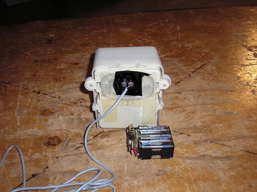
KCH510R2
Nov 13, 2006Utility Meter Transceiver
Equipment Class
DTS - Digital Transmission System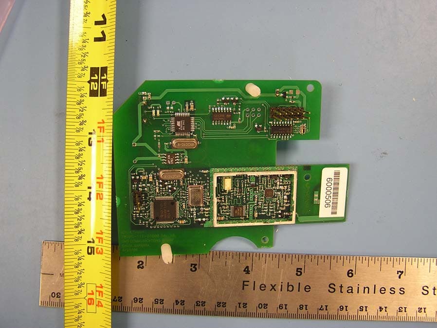
KCHMXU530T
Aug 22, 2006Radio Transceiver for Electric Meter
Equipment Class
DTS - Digital Transmission System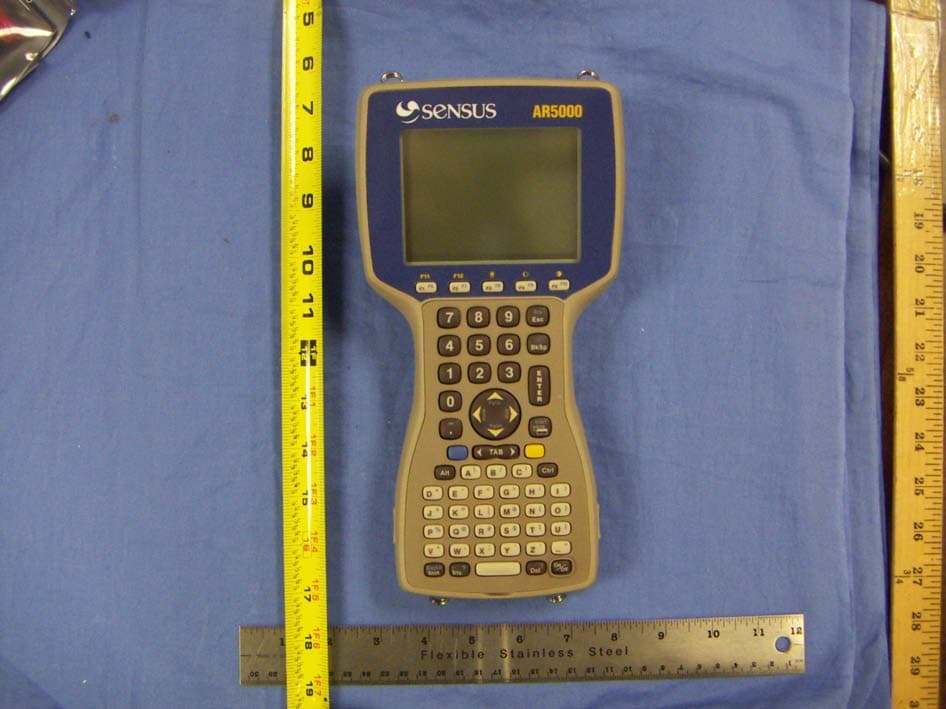
KCHAR5002
Jun 13, 2006Utility Meter RF Transceiver
Equipment Class
DXT - Part 15 Low Power Transceiver, Rx Verified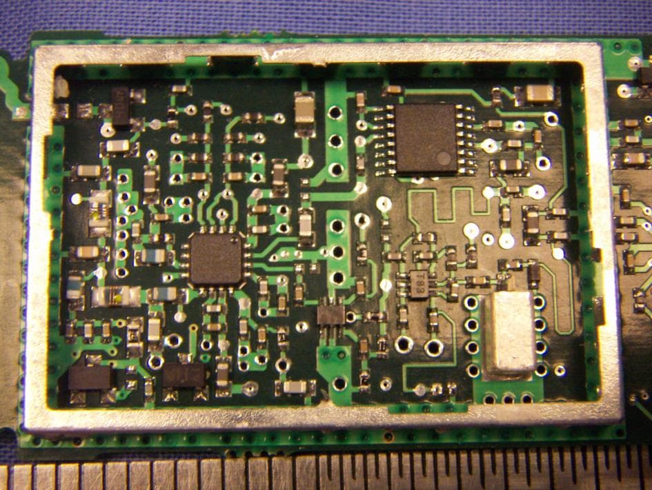
KCH520R
Jun 28, 2005900MHz DTS RF Module
Equipment Class
DTS - Digital Transmission System
KCHGS0003
Jan 19, 2005AUTOMATIC GAS METER TRANSMITTER
Equipment Class
DTS - Digital Transmission System