KCHMXU510Radio Transceiver For Meter Reading System
Sensus Metering Systems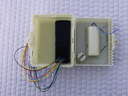
Click to zoom
Application Details
- Equipment Class
- DTS - Digital Transmission System
- Date of Grant
- Jan 16, 2003
- Application Purpose
- Original Equipment
- Date of Application
- Jan 16, 2003
- Equipment Note
- Radio Transceiver For Meter Reading System
- Frequency Range
- 903.80000000 - 926.20000000
- Company
- Sensus Metering Systems
- Country
- United States
Documents & Files
Document Text
Text extracted from the exhibit documents filed with the FCC. Open a document above to read the original.
Users Manual
The following information contains installation instructions for the Invensys RadioRead T Meter Transceiver Unit (MXU). The wiring con- nections are the same for both inside and pit set installations. Tech- niques may be different for the actual MXU placement in each type of installation. Note: This installation sheet is only for installation of the RadioRead MXU. For instructions on installing other AMR devices, please request and refer to the individual installation instructions for those devices. c SR II ® security screw socket with 1/4" nut driver or ratchet wrench c 3M Scotchlok ® UY-2 butt connector “gel-caps” c 3M Scotchlok ® E-9Y stepped jaw crimping tool with wire cutter c Wire stripper tool c Screwdrivers (Phillips and standard blade heads) c Power drill and bit (1/4") c 8 x 1" sheet metal screws c 1/2" Electrical Metallic Tubing (EMT) c Conduit cutting tool c Hammer c Conduit driver (available from Invensys) c Three-conductor solid wire (Invensys specification) I MPORTANT R ECOMMENDED T OOLS AND M ATERIALS 1 of 2 MXU Model 510 - Installation Wiring Diagram The MXU also requires proper programming of each port to match the device that is connected to the respective port. Refer to Invensys Pro- gramming Manual AMR-988. The MXU wiring instructions assume the utility meter with an encoder register or MultiRead module has been installed and the proper wire has been run to the MXU installation location. Three-conductor, 22 gauge, solid conductor cable is recommended. (For meter installation, refer to the installation information included in Invensys meter shipping cartons.) 1. Using the SR II security socket with ratchet wrench or nut driver, open the MXU enclosure by removing SR II type security screw. Bottom part of enclosure will contain the MXU battery and top part the electronics and connection wires. Connect the three wires from the encoder register or MultiRead module to the matching color wires on the MXU and the desired port. If not already done, strip approximately 2" off outer jacket of the encoder wire cable. The wire colors for each unit should be green , red , and black . Insert two matching color wire ends – red to red , green to green , and black to black into a UY-2 gel-cap with the color button of gel-cap facing away. (This provides a better view of wire positions inside the clear plastic gel-cap enabling the installer to see the wires are com- pletely and properly inserted.) Note: For the Schlumberger Proread encoder, the color coded wire connections are not standard – For Proread, connect the MXU red to Proread black, MXU green to Proread red, and MXU black to Proread green. Using gel-cap pliers, squeeze the gel-cap. This will splice the two wires and release the waterproof gel to seal the connection. The splice can be checked by pulling gently on the gel-cap while hold- ing the wires to be sure they are tight and secure. Repeat Step 2 instructions for the remaining two wire connections. Repeat con- nections to a second port, if required. * If any of the wire connections are not being used they should be capped at the end with a gel-cap. This is to prevent water intrusion via wicking through the exposed wire ends. The red , green , and black wires must be gel-capped individually. The green with white striped TouchRead sensor wires can be gel- capped together. Note: A Schlumberger Proread (ARB VI) register must be con- nected directly to an MXU port. The Proread register will not work through a MultiRead module connected to an MXU. 2. Connect the battery to the MXU electronics. Using the gel-cap con- necting technique described in Step 2 above, connect the red and white stripe wire from the battery to the red and white stripe wire from the MXU electronics. Repeat the procedure for the black and white stripe wire from the battery to the black and white stripe wire from the MXU. Caution: DO NOT cross connect the black and white and red and white stripe wires of the MXU and battery pack as this may cause damage to the MXU electronics. If using the optional TouchRead ® connection, go to Step 3. If not, skip to Step 4. 3. (Optional) TouchRead ® Connection (available for Invensys register encoders only) – The MXU includes a built-in TouchRead splitter connection to allow the encoder register to be interrogated by both RadioRead equipment and a remote TouchRead System sensor. I NSTALLATION - W IRING I NSTRUCTIONS The Model 510 MXU incorporates a two-port interface design. Hard- wire connections to either port from a compatible utility meter or Multi- Read module is the same for each port. Note: the wiring is different when connecting a Schlumberger Proread (ARB-VI) encoder to a port. G ENERAL I NFORMATION INSTALLATION INSTRUCTIONS Invensys RadioRead T Meter Transceiver Unit (MXU) Model 510 Invensys Metering Systems P.O. Box 487 450 N. Gallatin Avenue Uniontown, PA 15401 1-800-METER-IT 1-800-638-3748 FAX (Direct to Factory) Local: (724) 439-7729 Toll Free: 1-800-888-2403 Web site: www.ims.invensys.com select North American Water Email: [email protected] AUTHORIZED INVENSYS DISTRIBUTOR 2 of 2 Wall Mount TouchPad – Using two-conductor or three-conductor wire cable and gel-caps, connect wires to each of the green and white stripe wires from the MXU. Note: If three-conductor wire cable is used, the third wire is not utilized for the TouchRead Connection. At the TouchPad connection, connect the same two wires to the terminal screws on the back of the TouchPad. Caution: Be sure there is no bare wire-to-wire contact. (The TouchRead connection is non-polarity sensitive and will work as long as the same color wires are used at both ends of the connection. If three-conductor wire is used, be sure the third “dead” wire is not mistakenly connected at either end.) Repeat the connections for a second port if required. Pit-set Mount Sensor – The TouchRead pit-set sensor includes a factory-sealed three-conductor wire cable. Proper wire connections are therefore important. To activ…
Text truncated - open the document above for the full version.
Cover Letter(s)
tel: 650-726-1263 fax: 650-726-1252 [email protected] Thomas N. Cokenias EMC &Radio Approvals Test & Consulting Services for Commercial, Military, International Compliance P.O. Box 1086 El Granada, CA 94018 email: [email protected] FCC Laboratory 11 Dec 2002 7435 Oakland Mills Road Columbia, MD 21046 Attention: Application Examiner Reviewing Engineer Re: Request for confidentiality per Section 0.459 of FCC Rules Applicant: Invensys Metering Systems FCC ID: KCHMXU510 To whom it may concern, Request is hereby submitted, on behalf of my client, Invensys Metering Systems, to withhold from public review certain portions of the application for equipment certification for the referenced FCC identifier. In particular, the following sections of the application and report are requested to be kept confidential: Schematics Block Diagram Theory of Operations Internal Photos Rationale for request for confidentiality: Invensys has invested considerable time and materials in research and development to produce the referenced product. Disclosure of the confidential portions of this application to competitors would give them competitive advantage in developing similar products. JUSTIFICATION for INTERNAL PHOTOGRAPHS CONFIDENTIALITY The EUT will be filled with an opaque potting material in production. The potting material will make it very difficult to examine the circuit boards without damaging the unit. If you have questions or need further information, please contact the undersigned. Sincerely, tel: 650-726-1263 fax: 650-726-1252 [email protected] THOMAS N. COKENIAS EMC Consultant/Agent for Invensys
Cover Letter(s)
From: Tom Cokenias [[email protected]] Sent: Monday, January 13, 2003 11:23 AM To: [email protected] Subject: Invensys Metering Systems, FCC ID:KCHMXU510, AN02T2456 Mike, Please get back to me on whether answers to 1 and 2 are ok. Invensys needs this by the end of the week. Answer 3 I am waiting from Tim Harrington per his email below. If I don't get an answer Invensys instructed me to go ahead with the 20 cm statement, but they are not pleased with it: Question #1: Internal photos is listed in the request for confidentiality letter. It is FCC policy not to grant internal photos as confidential document. Please remove this request and provide revised letter. ANS1 The entire unit will be enclosed in black opaque potting material. The circuit boards woudl be ruined if one tried to remove the potting solution from a production unit. As such, an interested party would not be able to view the circuit boards, hence this request that photographs be kept confidential. Question #2: Page 3 of test report ( Radiated spurious emission tabular data @ 903.8 Fundamental frequency ), the average reading of fundamental frequency is 11.2 dBuV/m but the peak reading is 94.1dBuV/m. Please explain the huge difference between peak and average reading. In addition, average reading of fundamental is lower than spurious emissions which does not comply with 15.215(b) requirements. ANS2. The entry was a typo, it should have been 111.2 dBuV/m. Attached is corrected data sheet. Question #3: There is no RF warning statement in the user manual, suggest wordings may be " IMPORTANT NOTE: To comply with FCC RF exposure compliance requirements, The antenna(s) used for this transmitter must be installed to provide a separation distance of at least 20 cm from all persons and must not be co-located or operating in conjunction with any other antenna or transmitter." Please provide revised user manual to comply this requirement. ANS3 See above and email below: > >From: "Tim Harrington" <[email protected]> >To: "Joe Dichoso" <[email protected]>, <[email protected]> >Cc: "Andrew Leimer" <[email protected]>, "Martin Perrine" <[email protected]>, > "Rich Fabina" <[email protected]>, "Steven Dayhoff" <[email protected]>, > "Tim Harrington" <[email protected]> >X-OriginalArrivalTime: 07 Jan 2003 22:25:48.0090 (UTC) >FILETIME=[BA4279A0:01C2B69B] > > >You asked us this question last May, Tom. >I've been working on a policy and should be able to get back to you within the >next few days. > > > >>> Joe Dichoso 01/07/03 05:21PM >>> >You too Tom, Thanks for the Sees Candies. >For mobile devices, the 20 cm distance is maintained. >If you do not want the 20 cm RF safety distance, then you need to evaluate as >portable(<20 cm). >FYI... Mobile to portable requires a new FCC identifer. >Please contact Tim Harrington for future RF safety questions. >Regards, >Joe > > >>> Tom Cokenias 01/06/03 03:00PM >>> >Happy New Year Joe, > >I wish you and yours a healthy and prosperous 2003 (world peace too >if that's possible) > >I have an RF exposure question. It involves a 902-928 MHz DTS radio >used in a utility meter. > >Peak power is less than 23 dBm (22.6 measured) >Maximum antenna gain is 2.2 dBi >Far field MPE calculation is 6.3 cm > >The EUT transmits in bursts of 72msec. Under typical usage, there >are 5-10 burst transmissions per month. > >The utilities that buy this product have expressed hardship in >maintaining a 20cm separation under all installation conditions, such >as when meters are located on outside walls near sidewalks and >alleyways. To insure 20 cm separation under all conditions, long >standing practices would have to be modified and existing meter >locations would not be able to take advantage of a wireless >replacement unit. > >Source based averaging would bring TX power levels down to an >equivalent of about 1.5 mW, and calculated MPE of 0.4cm. > >Does the user manual still need to include the 20cm separation >distance statement? > >Thanks for you help on this. I look forward to hearing from you. > >best regards > >Tom Cokenias > >T.N. Cokenias Consulting >P.O. Box 1086 >El Granada CA 94018 > >tel 650 726 1263 >fax 650 726 1252 > >cell 650 302 0887
External Photos
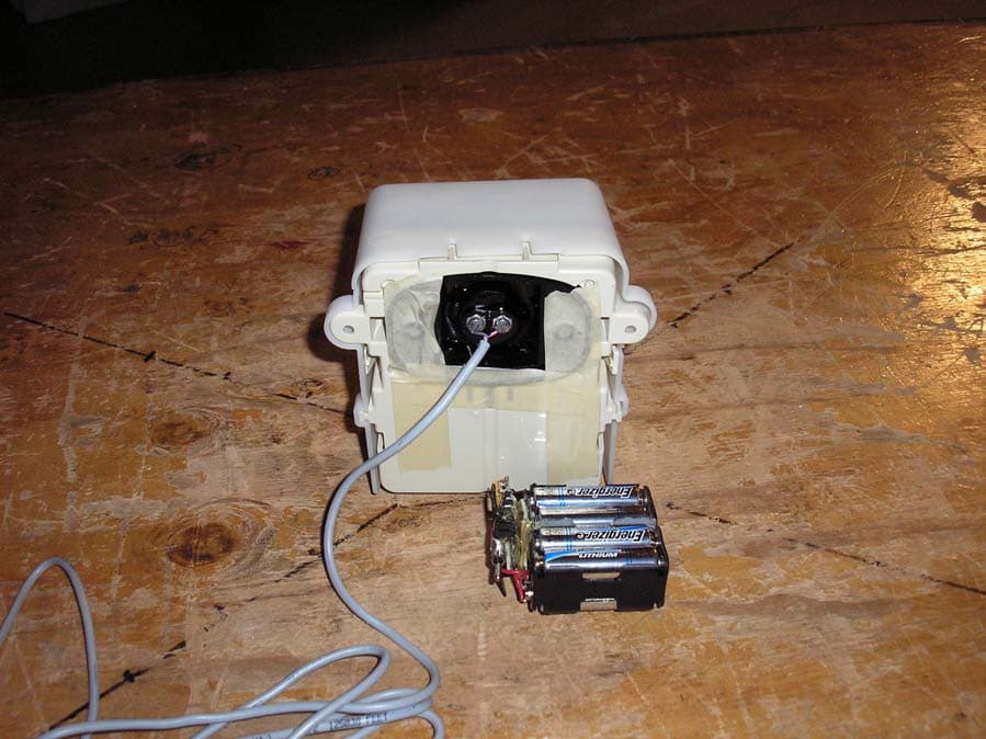
Product Photos Invensys MXU510 Product Photographs for KCHMXU510 Product Photos Invensys MXU510 Product Photos Invensys MXU510
ID Label/Location Info
CAM Products 2000(TM): C:\JOBS\Golden Puppy\FCC Submission Docs\KCHMXU510_FCC_ID_Label.cam
Test Report
FCC ID: KCHMXU510 Invensys MXU 510 Meter Transceiver Unit 1 of 22 900MHz DTS EMISSIONS TEST REPORT FOR A LOW POWER TRANSMITTER I. GENERAL INFORMATION Requirement:Federal Communications Commissions Test Requirements: 15.205, 15.207, 15.209, 15.247 Applicant:Invensys Metering Systems FCC ID: KCHMXU510 II. DESCRIPTION OF EQUIPMENT UNDER TEST (EUT) The Invensys FCC ID: KCHMXU510 is a digital transmission system (DTS) operating under the requirements in FCC Part 15. The product is used in a utility meter system for transmitting meter readings to a receiver unit owned by the utility. The product has an ASH receiver tuned to the utility licensed transmitter operating in the 952-956 MHz band. The licensed transmitter sends the transmit command to the MXU 510 The LCM operates in the U.S. ISM band between 902 and 928 MHz. Transmitter Specification TX Power22.6 dBm measured Frequency of operation903.8-926.2 MHz Data Rate15.625 kpbs in 72ms burst 6 dB bandwidth1.18 MHz Power sourceinternal lithium thionyl chloride battery 6 dB bandwidth1.18 MHz III. TEST LOCATION All tests were performed at: Compliance Certification Services 561F Monterey Road Morgan Hill, CA 95037 T.N. Cokenias8 December 2002 EMC Consultant/Agent for Invensys FCC ID: KCHMXU510 Invensys MXU 510 Meter Transceiver Unit 2 of 22 900MHz DTS 15.203 Antenna connector requirement The antenna is permanently attached to the product. For antenna conducted tests, a unit was modified by disconnecting the printed circuit antenna and replacing it with a 50 ohm coaxial cable connection terminated at one end with an SMA connector. 15.204 Antenna description The meter transceiver uses a printed circuit folded dipole antenna: Antenna descriptionGain printed ckt antenna2.2 dBi TEST DATA and TEST PROCEDURES - CCS Laboratory Radiated Emissions Test Requirement: 15.205, 15.247 Out of Band Measurements Test Requirement: 15.247 Measurement Equipment Used: HP 8564 Spectrum Analyzer, 1 - 9.5 GHz Miteq NSP2600-44 Microwave pre-amplifier, 1-26.5 GHz EMCO 3115 Double Ridged Horn antenna, 1 - 18 GHz Radiated emissions generated by the transmitter portion of the EUT were measured. 1. The EUT was placed on a wooden table resting on a turntable on the open air test site. Several utility meters were connected to the appropriate ports as typical loads. The search antenna was placed 3m from the EUT. The EUT antenna was mounted vertically as per normal installation. 2. The turntable was slowly rotated to locate the direction of maximum emission at each emission falling in the restricted bands of 15.205. 3. Radiated emissions were investigated for a LOW channel, a MID channel, and HIGH channel. Emissions were investigated to the 10 th harmonic. 4. Once maximum direction was determined, the search antenna was raised and lowered in both vertical and horizontal polarizations. The maximum readings so obtained are recorded in the data listed below. Test Results: Worst case results are presented. Refer to data sheets in separate attachments. Restricted band emissions meet 54 dBuV/m. Other undesired emissions from the transmitter meet the -20 dBc requirement in 15.247(c). Low Channel 11/11/02 FCC Measurement Compliance Certification Services, Morgan Hill Open Field Site Test Engr: Thanh Nguyen Project #: Company: Invensys Metering Systems EUT Descrip.: 902-928 MHz DSSS Automatic Meter Reading system EUT M/N: FCC ID: KCHMXU510 Test Target: 15.247, 15.205, 15.209 Equipment for 1-22 GHz:Equipment for 22 - 58 GHz: HP8566B AnalyzerHP8566B Analyzer HP 8449 Pe-ampHP 11975A Amplifier (LO) EMCO 3115 AntennaHP 11970K External mixer/antenna Cable:13.0feetCable: IF Only (321 MHz) Peak Measurements:Average Measurements: 1 MHz Resolution Bandwidth1MHz Resolution Bandwidth 1MHz Video Bandwidth10Hz Video Bandwidth fDistRead PkRead Avg.AFCLAmpD CorrHPFPeakAvgPk LimAvg LimPk MarAvg MarNotes GHzfeetdBuVdBuVdB/mdBdBdB dBuV/mdBuV/mdBuV/mdBuV/mdBdB 0.9033.394.111.2#N/A1.90.0-9.50.0#N/A#N/A74.054.0#N/A#N/AV 1.8063.354.845.327.02.90.0-9.50.075.365.874.054.01.311.8H 1.8063.355.38.727.02.90.0-9.50.075.829.274.054.01.8-24.8V 2.7103.358.549.729.93.5-36.0-9.51.047.438.674.054.0-26.6-15.4H 2.7103.358.351.529.93.5-36.0-9.51.047.240.474.054.0-26.8-13.6V 3.6153.352.240.532.54.1-35.3-9.51.045.033.374.054.0-29.0-20.7V 3.6153.353.842.832.54.1-35.3-9.51.046.635.674.054.0-27.4-18.4H 4.5203.354.545.233.04.8-34.6-9.51.049.139.874.054.0-24.9-14.2H 4.5203.353.543.033.04.8-34.6-9.51.048.137.674.054.0-25.9-16.4V 5.4233.352.541.535.25.3-34.4-9.51.050.139.174.054.0-23.9-14.9V 5.4233.352.040.535.25.3-34.4-9.51.049.638.174.054.0-24.4-15.9H 6.3263.354.042.535.55.9-34.5-9.51.052.440.974.054.0-21.6-13.1H 6.3263.357.050.735.55.9-34.5-9.51.055.449.174.054.0-18.6-4.9V 7.2303.355.544.237.06.3-34.6-9.51.055.744.474.054.0-18.3-9.6V 7.2303.355.546.737.06.3-34.7-9.51.055.546.774.054.0-18.5-7.3H 8.1343.353.841.837.76.7-34.7-9.51.055.043.174.054.0-19.0-10.9H 8.1343.353.342.037.76.7-34.7-9.51.054.543.274.054.0-19.5-10.8V 9.0383.353.241.738.47.1-34.9-9.51.055.343.874.054.0-18.7-10.2V 9.0383.354.743.538.47.1-34.9-9.51.056.845.674.054.0-17.2-8.4H DistDistance to AntennaD CorrDistance Correct to 3 metersPk LimPeak Field Strength Limit ReadAnalyzer ReadingAvgAverage Field Strength @ 3 mAvg MarMargin vs. Average Limit AFAntenna FactorPeakCalculated Peak Field StrengthPk MarMargin vs. Peak Limit CLCable LossHPFHigh Pass Filter ABOVE1GHz.XLS Mid Channel 11/11/02 FCC Measurement Compliance Certification Services, Morgan Hill Open Field Site Test Engr: Thanh Nguyen Project #: Company: Invensys Metering Systems EUT Descrip.: 902-928 MHz DSSS Automatic Meter Reading System EUT M/N: FCC ID: KCHMX510 Test Target: 15.247, 15.205, 15.209 Equipment for 1-22 GHz:Equipment for 22 - 58 GHz: HP8566B AnalyzerHP8566B Analyzer HP8449 Pre- ampHP 11975A Amplifier (LO) EMCO 3115 AntennaHP 11970K External mixer/antenna Cable:13.0feetCable: IF Only (321 MHz) Peak Measurements:Average Measurements: 1 MHz Resolution Bandwidth1MHz Resolution Bandwidth 1MHz Video Bandwid…
Text truncated - open the document above for the full version.
Test Report
Low Channel 11/11/02 FCC Measurement Compliance Certification Services, Morgan Hill Open Field Site Test Engr: Thanh Nguyen Project #: Company: Invensys Metering Systems EUT Descrip.: 902-928 MHz DSSS Automatic Meter Reading system EUT M/N: FCC ID: KCHMXU510 Test Target: 15.247, 15.205, 15.209 Equipment for 1-22 GHz:Equipment for 22 - 58 GHz: HP8566B AnalyzerHP8566B Analyzer HP 8449 Pe-ampHP 11975A Amplifier (LO) EMCO 3115 AntennaHP 11970K External mixer/antenna Cable:13.0feetCable: IF Only (321 MHz) Peak Measurements:Average Measurements: 1 MHz Resolution Bandwidth1MHz Resolution Bandwidth 1MHz Video Bandwidth10Hz Video Bandwidth fDistRead PkRead Avg.AFCLAmpD CorrHPFPeakAvgPk LimAvg LimPk MarAvg MarNotes GHzfeetdBuVdBuVdB/mdBdBdB dBuV/mdBuV/mdBuV/mdBuV/mdBdB 0.9033.394.1#N/A1.90.0-9.50.0#N/A74.054.0#N/AV 1.8063.354.845.327.02.90.0-9.50.075.365.874.054.01.311.8H 1.8063.355.38.727.02.90.0-9.50.075.829.274.054.01.8-24.8V 2.7103.358.549.729.93.5-36.0-9.51.047.438.674.054.0-26.6-15.4H 2.7103.358.351.529.93.5-36.0-9.51.047.240.474.054.0-26.8-13.6V 3.6153.352.240.532.54.1-35.3-9.51.045.033.374.054.0-29.0-20.7V 3.6153.353.842.832.54.1-35.3-9.51.046.635.674.054.0-27.4-18.4H 4.5203.354.545.233.04.8-34.6-9.51.049.139.874.054.0-24.9-14.2H 4.5203.353.543.033.04.8-34.6-9.51.048.137.674.054.0-25.9-16.4V 5.4233.352.541.535.25.3-34.4-9.51.050.139.174.054.0-23.9-14.9V 5.4233.352.040.535.25.3-34.4-9.51.049.638.174.054.0-24.4-15.9H 6.3263.354.042.535.55.9-34.5-9.51.052.440.974.054.0-21.6-13.1H 6.3263.357.050.735.55.9-34.5-9.51.055.449.174.054.0-18.6-4.9V 7.2303.355.544.237.06.3-34.6-9.51.055.744.474.054.0-18.3-9.6V 7.2303.355.546.737.06.3-34.7-9.51.055.546.774.054.0-18.5-7.3H 8.1343.353.841.837.76.7-34.7-9.51.055.043.174.054.0-19.0-10.9H 8.1343.353.342.037.76.7-34.7-9.51.054.543.274.054.0-19.5-10.8V 9.0383.353.241.738.47.1-34.9-9.51.055.343.874.054.0-18.7-10.2V 9.0383.354.743.538.47.1-34.9-9.51.056.845.674.054.0-17.2-8.4H DistDistance to AntennaD CorrDistance Correct to 3 metersPk LimPeak Field Strength Limit ReadAnalyzer ReadingAvgAverage Field Strength @ 3 mAvg MarMargin vs. Average Limit AFAntenna FactorPeakCalculated Peak Field StrengthPk MarMargin vs. Peak Limit CLCable LossHPFHigh Pass Filter ABOVE1GHz.XLS
Test Setup Photos
Test Set-up Photographs Invensys MXU 510 Test Set-up Photographs FCC ID: KCHMXU510 Conducted Antenna Emissions Test Set-up Photographs Invensys MXU 510 Radiated emissions above 1 GHz Test Set-up Photographs Invensys MXU 510 Radiated Emissions below 1 GHz
Contact Information
Applicant
Richard Daniel(Director, Engineering NPI and Project Management)
Test Firm
Compliance Certification Services IncSteve Cheng
Technical Specifications
| # | Rule Parts | Frequency Range | Power Output |
|---|---|---|---|
| 1 | 15C | 903.8 MHz - 926.2 MHz | 182.00 mW |
Other Applications from Sensus Metering Systems
KCH510R2
Nov 13, 2006Utility Meter Transceiver
Equipment Class
DTS - Digital Transmission System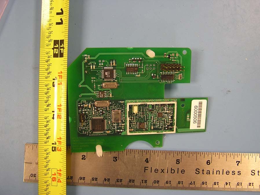
KCHMXU530T
Aug 22, 2006Radio Transceiver for Electric Meter
Equipment Class
DTS - Digital Transmission System
KCHAR5002
Jun 13, 2006Utility Meter RF Transceiver
Equipment Class
DXT - Part 15 Low Power Transceiver, Rx Verified
KCH520R
Jun 28, 2005900MHz DTS RF Module
Equipment Class
DTS - Digital Transmission System
KCHGS0003
Jan 19, 2005AUTOMATIC GAS METER TRANSMITTER
Equipment Class
DTS - Digital Transmission System