KCHMXU530EElectric Utility Meter for WLAN
Sensus Metering Systems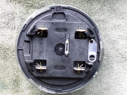
Click to zoom
Application Details
- Equipment Class
- DTS - Digital Transmission System
- Date of Grant
- Mar 02, 2003
- Application Purpose
- Original Equipment
- Date of Application
- Mar 02, 2003
- Equipment Note
- Electric Utility Meter for WLAN
- Frequency Range
- 903.80000000 - 926.20000000
- Company
- Sensus Metering Systems
- Country
- United States
Documents & Files
Document Text
Text extracted from the exhibit documents filed with the FCC. Open a document above to read the original.
Users Manual
iCon™ Form 2S and Form 12S Meters Physical Description FCC Compliance NOTE: This equipment has been tested and found to comply with the limits for a Class B digital device, pursuant to part 15 of the FCC Rules. These limits are designed to provide reasonable protection against harmful interference in a residential installation. This equipment generates, uses and can radiate radio frequency energy and, if not installed and used in accordance with the instructions, may cause harmful interference to radio communications. However, there is no guarantee that interference will not occur in a particular installation. If this equipment does cause harmful interference to radio or television reception, which can be determined by turning the equipment off and on, the user is encouraged to try to correct the interference by one or more of the following measures; – Reorient or relocate the receiving antenna – Increase the separation between the equipment and receiver – Connect the equipment into an outlet on a circuit different from that to which the receiver is connected – Consult the dealer or an experienced radio/TV technician WARNING: No party shall make any modifications or changes to the MXU Model 530E (the equipment) without the express written consent of Invensys Metering Systems. Doing so could result in the equipment becoming non-compliant with the requirements of the Federal Communication Commission Rules CFR47 Part 15 and could void the user’s authority to operate the equipment. Note: To comply with FCC RF exposure requirements in section 1.1307, a minimum separation distance of 20 cm (8 inches) is required between the antenna and all persons. FCC C OMPLIANCE Physical Description iCon™ Form 2S and Form 12S Meters Physical Description The iCon™ MXU 530-E Meter was designed to be assembled and disassembled without the use of tools. This modular design allows you to upgrade or repair a unit quickly and easily. The basic components of the iCon™ meter are depicted below and detailed following the diagram. MXU 530-E DISPLAY BOARD POWER SUPPLY BOARD Base Assembly The meter’s Base Assembly is molded from highly durable thermoplastics that provide a stable platform for the meter’s Sensor Module, Register display board and up to two additional option boards. The blades (or blade assembly) from the Sensor Module extend through the Base Assembly to connect to the service socket of the main power system. Sensor Module Power Supply The iCon™ meter uses a capacitive tap to provide a regulated voltage to the Sensor Module and the LCD display portion of the MXU 530-E board. The power supply can withstand a voltage transient as described in IEEE C62.41, Level C and applied in accordance with Section 5 of the ANSI C12.20-1998. iCon™ Form 2S and Form 12S Meters Physical Description Current Sensor Current is measured using a proprietary air-coupled current transformer. Sensor data, quantities proportional to the time derivative of the current, is streamed to the on-board metering chip. Metering Chip The iCon™ meter is pre-programmed at the factory for basic residential metering where 1 Wh equals 2 30 internal energy units. The metering chip measures voltage using a resistor divider, performs all energy calculations, and outputs billing data to the Register display board. The metering chip multiplies instantaneous current and voltage to calculate energy usage. Energy is read and accumulated into the integer register once every line cycle. The capacity of the internal register corresponds to 1024 Wh, and the total energy capacity of the software data register before rollover is approximately ±8.5e6 kWh. Under typical conditions, the internal register has the capacity to store approximately 80 years of metering data. The computed watthours is output in a variable frequency pulse waveform and instantaneous watt-hour. At calibration, the value of each pulse is set as close as practical to 1.0 watthours per pulse. Each pulse, measured from the rising edge of an output pulse to the rising edge of the next output pulse, is defined as the meter energy constant Ke and can be provided as a test output. Power supply board This board utilizes the 120/240 VAC mains to supply a regulated voltage to the radio portion of the MXU 530-E display board. MXU 530-E display board The LCD display portion of the board consists of a control processor (register), and LCD display. The radio portion of the board consists of a spread spectrum direct sequence radio used to transmit the electric meter data over the air. Modules for advanced options, such as AMR, are integrated into the display board in the area below the LCD display. The cable between the Register display board and the Sensor Module carries SPI, interrupt, and pulse output signals. Control Processor (register) The control processor accumulates the active energy register data and converts the readings to kWh. These active energy readings (or a short-term average of these readings) are defined as “Instantaneous kWh”. The accumulation of these readings is defined as “Total kWh”. NOTE During the normal operation of the meter, the Total kWh register can be cleared, but cannot be set to a specific figure. Refer to Error! Reference source not found. on page Error! Bookmark not defined.. The Total kWh displayed on the LCD, described below, is to the decimal resolution specified at time of order. The full resolution of the Ke value is maintained in the Physical Description iCon™ Form 2S and Form 12S Meters meter’s memory for internal computation. All billing data and system information is stored in the meter’s non-volatile memory. System information, compliant with ANSI C12.19a data table format, includes the following: User Data Calibration Date Set by Invensys when the meter is first calibrated User Configuration Date Set by the utility when the meter is configured for use Serial Number 16 digit decimal serial number Identification 20 decimal digits of identification data kh Text r…
Text truncated - open the document above for the full version.
Cover Letter(s)
tel: 650-726-1263 fax: 650-726-1252 [email protected] Thomas N. Cokenias EMC &Radio Approvals Test & Consulting Services for Commercial, Military, International Compliance P.O. Box 1086 El Granada, CA 94018 email: [email protected] FCC Laboratory 20 February 2003 7435 Oakland Mills Road Columbia, MD 21046 Attention: Application Examiner Reviewing Engineer Re: Request for confidentiality per Section 0.459 of FCC Rules Applicant: Invensys Metering Systems FCC ID: KCHMXU530E To whom it may concern, Request is hereby submitted, on behalf of my client, Invensys Metering Systems, to withhold from public review certain portions of the application for equipment certification for the referenced FCC identifier. In particular, the following sections of the application and report are requested to be kept confidential: Schematics Block Diagram Theory of Operations Rationale for request for confidentiality: Invensys has invested considerable time and materials in research and development to produce the referenced product. Disclosure of the confidential portions of this application to competitors would give them competitive advantage in developing similar products. If you have questions or need further information, please contact the undersigned. Sincerely, THOMAS N. COKENIAS EMC Consultant/Agent for Invensys tel: 650-726-1263 fax: 650-726-1252 [email protected]
Cover Letter(s)
From: Tom Cokenias [[email protected]] Sent: Friday, February 28, 2003 1:28 AM To: Mike Kuo Subject: Re: FW: Invensys Metering Systems, FCC ID:KCHMXU530E, AN03T2617 Hello Mike, The fundamental emissions levels on page 4 are correct. The readings on the harmonic data pages were taken with the HP filter and with the horn antenna. The HPF attenuates the fundamental, and the horn antenna is not calibrated for the 900 MHz band. The readings should not have been entered onto the spreadsheet by the technician. I have corrected the test report by removing the erroneous entries. Modified test report is attached. Hopefully you will be able to issue the grant for this, but if you have more questions, I will be at CCS with clients on Friday best regards Tom >-----Original Message----- >From: CERTADM >Sent: Thursday, February 27, 2003 2:30 PM >To: '[email protected]' >Subject: Invensys Metering Systems, FCC ID:KCHMXU530E, AN03T2617 > > >Notice_content > ------------- >Question #1: Page 4 of test report includes the fundamental field strength >level measured at 3 meter. The highest field strength measured for low >Channel is 117.36dBuV/m, Middle channel:115.69dBuV/m and high channel >:116.77dBuV/m. However, fundamental field strength also reported in page >5,6, and 7 which were measured with distance of 3.3 ft with RBW=1MHz. >Low:79.3dBuv/m, Middle:78dBuV/m and high:106.3dBuV/m. In particularly, the >2nd harmonics of Low and Middle channel are over the general requirement. >Since the 3nd harmonics are not in 15.205 restricted band, comply with >15.209 limits are necessary. However, for those harmonics not within the >15.205 table, the field strength shall below 20dB of fundamental field >strength. Since there are two readings with two different setup are reported >to address fundamental field strength, the 2nd harmonics may not comply with >15.247( c ) requirement. Please address this issue. > >Best Regards > >Mike Kuo >The items indicated above must be submitted before processing can continue >on the above referenced application. Failure to provide the requested >information within 60 days of the original e-mail date may result in >application dismissal and forfeiture of the filing fee. Also, please note >that partial responses increase processing time and should not be submitted. >Any questions about the content of this correspondence should be directed to >the e-mail address listed below the name of the sender.
External Photos
Invensys Metering Systems FCC ID: KCHMXU530E Product Photographs Invensys Metering Systems FCC ID: KCHMXU530E Invensys Metering Systems FCC ID: KCHMXU530E
ID Label/Location Info
FCC ID: KCHMXU530E Label and Label Location
Internal Photos
Invensys Metering Systems FCC ID: KCHMXU530E Invensys Metering Systems FCC ID: KCHMXU530E Invensys Metering Systems FCC ID: KCHMXU530E Invensys Metering Systems FCC ID: KCHMXU530E Invensys Metering Systems FCC ID: KCHMXU530E Invensys Metering Systems FCC ID: KCHMXU530E Invensys Metering Systems FCC ID: KCHMXU530E Invensys Metering Systems FCC ID: KCHMXU530E Invensys Metering Systems FCC ID: KCHMXU530E
RF Exposure Info
FCC ID: KCHMXU530E Invensys MXU 530E Meter Transceiver Unit 27 of 27 900MHz DTS RF Exposure (MPE) Calculations 905 - 924.6 MHz DTS Radio Applicant: Invensys Metering Systems FCC ID: KCHMXU530E RF Hazard Distance Calculation (worst case) mW/cm2 from Table1:0.60 Max RF PowerTX AntennaMPE P, dBmG, dBiSafe Distance, cm 21.62.25.6 Basis of Calculations: E^2/3770 = S, mW/cm2 E, V/m = (Pwatts*Ggain*30)^.5/d, meters d = ((Pwatts*G*30)/3770*S))^0.5Pwatts*Ggain = 10^(PdBm-30+GdBi)/10)
Test Report
FCC ID: KCHMXU530E Invensys MXU 530E Meter Transceiver Unit 1 of 27 900MHz DTS EMISSIONS TEST REPORT FOR A LOW POWER TRANSMITTER I. GENERAL INFORMATION Requirement:Federal Communications Commissions Test Requirements: 15.205, 15.207, 15.209, 15.247 Applicant:Invensys Metering Systems FCC ID: KCHMXU530E II. DESCRIPTION OF EQUIPMENT UNDER TEST (EUT) The Invensys FCC ID: KCHMXU530E is a digital transmission system (DTS) operating under the requirements in FCC Part 15. The product is an electric utility meter that transmits meter readings to a receiver unit owned by the utility. The product has a receiver tuned to the utility licensed transmitter operating in the 952-956 MHz band. The licensed transmitter sends the transmit command to the MXU 530E The MXU530E operates in the U.S. ISM band between 902 and 928 MHz. Transmitter Specification TX Power21.6 DBMS measured Frequency of operation903.8-926.2 MHz Data Rate15.625 kpbs in 72ms burst 6 dB bandwidth1.18 MHz Power source240 VAC 60 Hz III. TEST DATES AND TEST LOCATION Testing was performed 14 - 15 January 2003. All tests were performed at: Compliance Certification Services 561F Monterey Road Morgan Hill, CA 95037 T.N. Cokenias16 February 2003 EMC Consultant/Agent for Invensys FCC ID: KCHMXU530E Invensys MXU 530E Meter Transceiver Unit 2 of 27 900MHz DTS 15.203 Antenna connector requirement The antenna is permanently attached to the product. For antenna conducted tests, a unit was modified by disconnecting the printed circuit antenna and replacing it with a 50 ohm coaxial cable connection terminated at one end with an SMA connector. 15.204 Antenna description The meter transceiver uses a printed circuit folded dipole antenna: Antenna descriptionGain printed ckt antenna2.2 dBi TEST DATA and TEST PROCEDURES - CCS Laboratory Radiated Emissions Test Requirement: 15.205, 15.247 Out of Band Measurements Test Requirement: 15.247 Measurement Equipment Used: HP 8592EM Spectrum Analyzer Miteq NSP2600-44 Microwave pre-amplifier, 1-26.5 GHz EMCO 3115 Double Ridged Horn antenna, 1 - 18 GHz Radiated emissions generated by the transmitter portion of the EUT were measured. 1. The EUT was placed on a wooden table resting on a turntable on the open air test site. Several utility meters were connected to the appropriate ports as typical loads. The search antenna was placed 3m from the EUT. The EUT antenna was mounted vertically as per normal installation. 2. The turntable was slowly rotated to locate the direction of maximum emission at each emission falling in the restricted bands of 15.205. 3. Radiated emissions were investigated for a LOW channel, a MID channel, and HIGH channel. Emissions were investigated to the 10 th harmonic. 4. Once maximum direction was determined, the search antenna was raised and lowered in both vertical and horizontal polarizations. The maximum readings so obtained are recorded in the data listed below. Test Results: Worst case results are presented. Refer to data sheets in separate attachments. Restricted band emissions meet 54 dBuV/m. Other undesired emissions from the transmitter meet the -20 dBc requirement in 15.247(c). FCC ID: KCHMXU530E Invensys MXU 530E Meter Transceiver Unit 3 of 27 900MHz DTS Radiated Emissions Test Requirement: 15.109 Measurement Equipment Used: HP 8593EM Spectrum Analyzer, 30-1000 MHz HP 8447D Pre-amplifier, .1 - 1300 MHz Schaffner/Chase CBL6112B Bilog Antenna, 30 - 2000 MHz Radiated emissions generated by the digital portion of the EUT were measured. 1. The EUT was placed on a wooden table resting on a turntable on the open air test site. The search antenna was placed 3m from the EUT. The EUT antenna was mounted vertically as per normal installation. The EUT was set to transmit continuously on the MID channel. 2. The turntable was slowly rotated to locate the direction of maximum emission at each emission falling in the restricted bands of 15.205. 3. Once maximum direction was determined, the search antenna was raised and lowered in both vertical and horizontal polarizations. The maximum readings so obtained are recorded in the data listed below. Test Results: EUT meets requirements. No radiated emissions were detected coming from the 952-956 MHz receiver portion of the EUT. A plot of antenna port conducted receiver emissions is attached . Refer to data spreadsheet below for emissions from the 902-928 MHz transceiver. 01/14/034:21 PM Invensys Electric Meter Radio Transceiver EUT Only FCC 15.247 Tx 01/14/03 Freq.ReadingAFClossPre-ampLevelLimitMarginPolAzHeightMark (MHz)(dBuV)(dB)(dB)(dB)(dBuV/m)FCC_B(dB)(H/V)(Deg)(Meter)(P/Q/A) Hi Ch 926.2Mhz 926.20114.6622.855.1327.90114.7446.0068.743mV0.001.50P 926.20116.6922.855.1327.90116.7746.0070.773mH0.001.50P Mid Channal 915MHz 915.00115.0922.705.0927.93114.9546.0068.953mV0.001.20P 915.00115.8322.705.0927.93115.6946.0069.693mH0.002.00P Low Ch 903.8MHz 903.80116.0422.555.0427.96115.6846.0069.683mV0.001.50P 903.80117.7222.555.0427.96117.3646.0071.363mH0.001.20P Total data #: 6 V.2a Company: EUT Description: Test Configuration : Type of Test: Mode of Operation: FCC, VCCI, CISPR, CE, AUSTEL, NZ UL, CSA, TUV, BSMI, DHHS, NVLAP 561F MONTEREY ROAD, SAN JOSE, CA 95037-9001 PHONE: (408) 463-0885 FAX: (408) 463-0888 Project #: Report #: Date& Time: Test Engr: A-Site nmlkji A-Site nmlkji B-Site nmlkj B-Site nmlkj C-Site nmlkj C-Site nmlkj F-Site nmlkj F-Site nmlkj 6 Worst Data Descending 01/14/03 High Frequency Measurement Compliance Certification Services, Morgan Hill Open Field Site Test Engr: Chin Pang Project #: Company: Invensys EUT Descrip.: Electric meter Radio Transceiver 902-928MHz DTS EUT M/N: MXU4E Test Target: FCC 15.247 Mode Oper: TX Test Equipment: 15 Peak Measurements:Average Measurements: 1 MHz Resolution Bandwidth1 MHz Resolution Bandwidth 1MHz Video Bandwidth10Hz Video Bandwidth Low Channel 903.6MHz fDistRead PkRead Avg.AFCLAmpD CorrHPFPeakAvgPk LimAvg LimPk MarAvg MarNotes GHzfeetdBuVdBuVdB/mdBdBdB dBuV/mdBuV/mdBuV/mdBuV/mdBdB 1.8073.386.085.127.13.4-36.4…
Text truncated - open the document above for the full version.
Test Setup Photos
Invensys Metering Systems FCC ID: KCHMXU530E Test Set-up Photographs14-15 January 2003 Invensys Metering Systems FCC ID: KCHMXU530E AC Line Conducted Invensys Metering Systems FCC ID: KCHMXU530E Antenna output conducted set-up Invensys Metering Systems FCC ID: KCHMXU530E Radiated emissions test set-up Invensys Metering Systems FCC ID: KCHMXU530E Radiated emissions test set-up
Contact Information
Applicant
Richard Daniel(Director, Engineering NPI and Project Management)
Test Firm
Compliance Certification Services IncSteve Cheng
Technical Specifications
| # | Rule Parts | Frequency Range | Power Output |
|---|---|---|---|
| 1 | 15C | 903.8 MHz - 926.2 MHz | 145.00 mW |
Other Applications from Sensus Metering Systems
KCH510R2
Nov 13, 2006Utility Meter Transceiver
Equipment Class
DTS - Digital Transmission System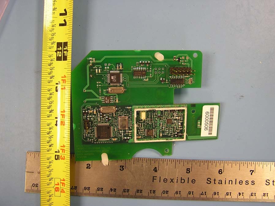
KCHMXU530T
Aug 22, 2006Radio Transceiver for Electric Meter
Equipment Class
DTS - Digital Transmission System
KCHAR5002
Jun 13, 2006Utility Meter RF Transceiver
Equipment Class
DXT - Part 15 Low Power Transceiver, Rx Verified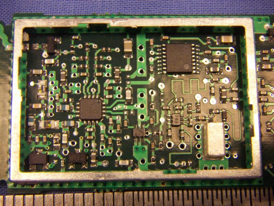
KCH520R
Jun 28, 2005900MHz DTS RF Module
Equipment Class
DTS - Digital Transmission System
KCHGS0003
Jan 19, 2005AUTOMATIC GAS METER TRANSMITTER
Equipment Class
DTS - Digital Transmission System