KDS-PW2-001Transceiver Controller for photographic strobe lig
Lab Partners Associates Inc
Click to zoom
Application Details
- Equipment Class
- DXT - Part 15 Low Power Transceiver, Rx Verified
- Date of Grant
- Mar 29, 1999
- Application Purpose
- Original Equipment
- Date of Application
- Jan 21, 1999
- Equipment Note
- Transceiver Controller for photographic strobe lig
- Frequency Range
- 344.00000000 - 354.00000000
- Company
- Lab Partners Associates Inc
- Country
- United States
Documents & Files
Document Text
Text extracted from the exhibit documents filed with the FCC. Open a document above to read the original.
Users Manual
The PocketWizard Max Users Manual Put the magic of a Wizard into your photos LPA Design So. Burlington VT Users Manual Rev 0.1 Current Rev's: Hardware Software Transmitter 1.0 1.0 Receiver 1.0 1.0 Last Revision Date: 12/31/98 Mfg. by: LPA Design 1350 Shelburne Road, Suite 265 So. Burlington, VT 05403 Phone: 1-802-864-8LPA Factory Fax: 1-802-658-6125 Sales:1-603-664-5010 Tech Support:1-603-664-5010 Sales/Tech Fax:1-603-664-9100 Sales E-Mail:sales @ lpadesign.com Web Page: E-Mail:support @ lpadesign.comhttp://www.lpadesign.com Table Of Contents ·Introduction / Features · Getting Started / Using your PocketWizard Max · Installing Batteries · Connecting the Transmitter to the Camera · Connecting the Receiver to a Flash Pack · Connecting the Transmitter to a Local Strobe · Transmitter and Receiver Orientation · Care and Feeding · Troubleshooting Guide · Warranty · Obtaining Technical Support Introduction Congratulations on your purchase of the PocketWizard Max radio slave. This is the newest entry in the most reliable line of radio slave products available. The PocketWizard Max is a fully digital radio system, making use of a microprocessor in both the transmitter and the receiver. Digital signaling allows the PocketWizard Max to reject spurious noise, and to receive weak signals without any degradation in performance. PocketWizard Max Features ·Sixteen original PocketWizard and PocketWizard Plus compatible channels, plus... · Sixteen new channels with four channel select ability. · Hot shoe and 1/4-20 mounting features built in · LCD Display to show status and settings · Keypad for easy changes to settings · Regulated power supply - no performance degradation until low battery indication · Digital trigger signal virtually eliminates false fires · Sync at speeds up to 1/250 second with a focal plane shutter or 1/500 second with a lief shutter (it takes approximately 540uS for the receiver to respond to a sync) · Will trigger most cameras with motor drive ports · Allows you to use a strobe you carry with you, a remote strobe, or both · Light weight - weighs less than 4.5 ounces with batteries. · Uses 2 AA batteries or AC adapter Getting Started Using your PocketWizard Max 13.Install batteries or use an AC adapter in the transmitter and receiver. 14. Attach a sync cord (PC to miniphone is the most common) from your camera to the Sync In connector on the transmitter or use the hot shoe to mount the transmitter to your camera. Note that the Sync In and Sync Out jacks look the same,. 15. Attach a sync cord from the Sync Out connector on the receiver to your strobe pack 16. For quick and simple setup, or for use with older PocketWizards, use the up and down keys (triangular keys) to change the channel number displayed on the LCD screen to channel 1 thru 16. For more advanced uses, see “4-Channel Triggering” section. Be sure to set the transmitter and receiver to the same channel number. 17. Turn the transmitter and receiver on. They will automatically sync up to 1/250th of a second with a focal plane shutter and 1/500 with a lief shutter 18. Verify that the light on the receiver blinks every few seconds 19. Verify that the light on the transmitter double blinks every few seconds 20. Move the LOCAL - BOTH - REMOTE selector switch on the transmitter to the Both position 21. Press the Test Fire button on the transmitter and confirm that the remote strobe goes off. The receiver will stay activated as long as you hold the Test Fire button. Installing Batteries To install batteries, open the battery compartment door, and insert two AA batteries. Make sure that they are in the proper orientation, as shown on the label in the battery compartment. LPA recommends the use of Alkaline batterys only. Standard batteries and rechargeable batteries will not perform well. Lithium batteries will give you approximately the same life expectancy as Alkaline batteries and cost more. When to Change Batteries In the upper left hand corner of the LCD display is a battery icon with several segments. The segments show the approximate battery level left. If the battery is new, it should show a “full” battery, or all segments lit. As the battery wears down, segments will disappear. When the battery needs replacing, all the segments will have disappeared and the battery outline will blink. Expected battery life for the receiver is about 120 hours, the transmitter should last about 200 hours. Connecting the Transmitter to the Camera To connect the PocketWizard Max transmitter to the camera you have two choices. The preferred method of connecting is to use the built in hot-shoe. Slide the PocketWizard Max into the hot shoe on your camera. If you do not have a hot shoe, you will need a PC to miniphone cable. The miniphone end plugs into the Sync In terminal on the transmitter and the PC connection plugs into your camera's PC connector. Connecting the Receiver to the Flash Pack To connect a receiver to a flash pack requires a cable with a mini phone plug for the Sync Out terminal on the receiver and the appropriate connector for your strobe. Sync cables are available for most popular strobes. (see the included accessories list). Connecting the Transmitter to a Local Strobe The transmitter is equipped with a miniphone connector labeled Sync Out. With the appropriate adapter or cable, a strobe pack can be fired by cable from the transmitter without the use of a receiver. To fire the local pack, the local - both - remote switch should be in the Local or Both position. NOTE: Most modern flash packs have low voltage, low current sync terminals. Some older packs have as much as 400 volts applied across the sync terminals. The PocketWizard Max is designed to work with voltages as high as 300 volts, and may not work with higher voltage packs. If you have an older flash unit, check with the manufacturer to make sure your pack will not exceed these limits. You may also purchase an LVT (Low Voltage Trigger) from LPA Design or your strobe manu…
Text truncated - open the document above for the full version.
Internal Photos
LPA Design PocketWizard Max (FCC ID: KDS-PW2-001) Internal Photos 1) 2) LPA Design PocketWizard Max (FCC ID: KDS-PW2-001) Internal Photos 3) 4) LPA Design PocketWizard Max (FCC ID: KDS-PW2-001) Internal Photos 5) 6) LPA Design PocketWizard Max (FCC ID: KDS-PW2-001) Internal Photos 7) 8) LPA Design PocketWizard Max (FCC ID: KDS-PW2-001) Internal Photos 9)
Test Report
July 9, 2001 Federal Communications Commission Equipment Authorization Branch 7435 Oakland Mills Road Columbia, MD 21046 Dear Sir/Madam: Enclosed you will find an application for Certification of a PocketWizard Max Intentional Radiator, FCC ID: KDS-PW2-001. Certification is requested to the requirements of Part 15, Subpart C of the Commission’s rules. This application is being filed by Retlif Testing Laboratories on behalf of LPA Design. I trust that you will find the enclosed application to be complete; however, should you have any questions or require any additional information, please feel free to contact us. Very truly yours, RETLIF TESTING LABORATORIES Scott Wentworth Manager Enc. (as stated) Test Report No. R-3378N FCC ID: KDS-PW2-001 APPLICANT LPA Design 1350 Shelburne Road South Burlington, VT 05403 MANUFACTURER SAME Test Report No. R-3378N FCC ID: KDS-PW2-001 Test Report No. R-3378N FCC ID: KDS-PW2-001 TEST SPECIFICATION: FCC Rules and Regulations Part 15, Subpart C, Para. 15.231 Test Report No. R-3378N FCC ID: KDS-PW2-001 TEST PROCEDURE: ANSI C63.4:1992 Test Report No. R-3378N FCC ID: KDS-PW2-001 Test Report No. R-3378N FCC ID: KDS-PW2-001 Test Report No. R-3378N FCC ID: KDS-PW2-001 TEST SAMPLE DESCRIPTION Test Report No. R-3378N FCC ID: KDS-PW2-001 BRANDNAME: PocketWizard Max MODEL: N/A Test Report No. R-3378N FCC ID: KDS-PW2-001 Test Report No. R-3378N FCC ID: KDS-PW2-001 TYPE: Intentional Radiator - Transceiver Test Report No. R-3378N FCC ID: KDS-PW2-001 Test Report No. R-3378N FCC ID: KDS-PW2-001 POWER REQUIREMENTS: 3VDC (Internal Battery or External Power Supply) Test Report No. R-3378N FCC ID: KDS-PW2-001 Test Report No. R-3378N FCC ID: KDS-PW2-001 FREQUENCY OF OPERATION RANGE: 344MHz to 354MHz Test Report No. R-3378N FCC ID: KDS-PW2-001 TEST FREQUENCIES: 346.5MHz and 349.0MHz Test Report No. R-3378N FCC ID: KDS-PW2-001 Test Report No. R-3378N FCC ID: KDS-PW2-001 TESTS PERFORMED Test Report No. R-3378N FCC ID: KDS-PW2-001 Para. 15.231(a), Radiated Emissions, Fundamental and Harmonics Test Report No. R-3378N FCC ID: KDS-PW2-001 Para. 15.231(c), Occupied Bandwidth Test Report No. R-3378N FCC ID: KDS-PW2-001 Para. 15.207(a), Conducted Emissions Test Report No. R-3378N FCC ID: KDS-PW2-001 Test Report No. R-3378N FCC ID: KDS-PW2-001 REPORT OF MEASUREMENTS Test Report No. R-3378N FCC ID: KDS-PW2-001 Applicant: LPA Design Test Report No. R-3378N FCC ID: KDS-PW2-001 Device:Transceiver Test Report No. R-3378N FCC ID: KDS-PW2-001 FCC ID: KDS-PW2-001 Test Report No. R-3378N FCC ID: KDS-PW2-001 Power Requirements: 3VDC (Internal Battery or External Power Supply) Test Report No. R-3378N FCC ID: KDS-PW2-001 Applicable Rule Section:Part 15, Subpart C, Section 15.231 Test Report No. R-3378N FCC ID: KDS-PW2-001 REPORT OF MEASUREMENTS (continued) Test Report No. R-3378N FCC ID: KDS-PW2-001 Test Report No. R-3378N FCC ID: KDS-PW2-001 TEST RESULTS Test Report No. R-3378N FCC ID: KDS-PW2-001 Test Report No. R-3378N FCC ID: KDS-PW2-001 15.231 (a) -The device is a transceiver for remote control of photographic strobes. Test Report No. R-3378N FCC ID: KDS-PW2-001 Test Report No. R-3378N FCC ID: KDS-PW2-001 15.231 (a)(1) &-The transmitter is manually operated and ceases transmission less than 5 Test Report No. R-3378N FCC ID: KDS-PW2-001 15.231 (2) seconds after deactivation. Test Report No. R-3378N FCC ID: KDS-PW2-001 Test Report No. R-3378N FCC ID: KDS-PW2-001 15.231 (a)(3) - The transmitter does not perform periodic transmissions at regularly predetermined Test Report No. R-3378N FCC ID: KDS-PW2-001 intervals. Test Report No. R-3378N FCC ID: KDS-PW2-001 Test Report No. R-3378N FCC ID: KDS-PW2-001 15.231 (a)(4)-The device is not employed for RC purposes involving security. Test Report No. R-3378N FCC ID: KDS-PW2-001 Test Report No. R-3378N FCC ID: KDS-PW2-001 15.231 (b) -The field strength at 346.5MHz did not exceed 77.3 dBμV/M (7,328 μV/M). Test Report No. R-3378N FCC ID: KDS-PW2-001 The field strength at 349.0MHz did not exceed 77.4 dBμV/M (7,413 μV/M). Test Report No. R-3378N FCC ID: KDS-PW2-001 The requirements of section 15.35 for averaging pulsed emissions and for Test Report No. R-3378N FCC ID: KDS-PW2-001 limiting peak emissions were met. Test Report No. R-3378N FCC ID: KDS-PW2-001 Test Report No. R-3378N FCC ID: KDS-PW2-001 The field strength of harmonic and spurious emissions did not exceed Test Report No. R-3378N FCC ID: KDS-PW2-001 732μV/M or 741μV/M. Test Report No. R-3378N FCC ID: KDS-PW2-001
Test Report
1=RF ON 0=RF OFF GIVE RECIVER AGC SETTLING TIME Worst Case Duty Cycle Calculations: 4.90 ms OFF TIME 5.350ms TOTAL TIME Per transmission 0.450ms ON TIME (MAX) Worst Case Duty Cycle Calculations: 4.86 ms OFF TIME 5.325ms TOTAL TIME Per transmission 0.465ms ON TIME (MAX) PocketWizard MAX Transmitter Duty Cycle START OF CODE END OF CODE 4.8ms PAUSE EOT SIGNAL The PocketWizard MAX has two command packet formats: A) Legacy PocketWizard compatible format (slightly modified), and B) New PocketWiazrd MAX format (bit time shorter and more bits) 1=RF ON 0=RF OFF GIVE RECIVER AGC SETTLING TIME Trigger Input Time = 0 0.450ms ----------- X 100% = 8.42% duty cycle 5.350ms 20 log (.0842) = -21.494 dB 0.465ms ----------- X 100% = 08.732% duty cycle 5.325ms 20 log (.08732) = -21.1773 dB PAUSE START OF CODE Up to 24 command bits at 15uS bit spacing 12 command bits at 25uS bit spacing END OF CODE 4.8ms EOT SIGNAL A) B) FCC ID: KDS-PW2-001
Test Report
July 1, 2001 Federal Communications Commission Equipment Authorization Branch 7435 Oakland Mills Road Columbia, MD 21046 Dear Sir/Madam: Enclosed you will find an application for Certification of a PocketWizard Max Intentional Radiator, FCC ID: KDS-PW2-001. Certification is requested to the requirements of Part 15, Subpart C of the Commission’s rules. This application is being filed by Retlif Testing Laboratories on behalf of LPA Design. I trust that you will find the enclosed application to be complete; however, should you have any questions or require any additional information, please feel free to contact us. Very truly yours, RETLIF TESTING LABORATORIES Scott Wentworth Manager Enc. (as stated) Test Report No. R-3378N FCC ID: KDS-PW2-001 APPLICANT LPA Design 1350 Shelburne Road South Burlington, VT 05403 MANUFACTURER SAME TEST SPECIFICATION: FCC Rules and Regulations Part 15, Subpart C, Para. 15.231 TEST PROCEDURE: ANSI C63.4:1992 TEST SAMPLE DESCRIPTION BRAND NAME: PocketWizard Max MODEL: N/A TYPE: Intentional Radiator - Transceiver POWER REQUIREMENTS: 3VDC (Internal Battery or External Power Supply) FREQUENCY OF OPERATION RANGE: 344MHz to 354MHz TEST FREQUENCIES: 346.5MHz and 349.0MHz TESTS PERFORMED Para. 15.231(a), Radiated Emissions, Fundamental and Harmonics Para. 15.231(c), Occupied Bandwidth Para. 15.207(a), Conducted Emissions REPORT OF MEASUREMENTS Applicant: LPA Design Device:Transceiver FCC ID: KDS-PW2-001 Power Requirements: 3VDC (Internal Battery or External Power Supply) Applicable Rule Section:Part 15, Subpart C, Section 15.231 Test Report No. R-3378N FCC ID: KDS-PW2-001 REPORT OF MEASUREMENTS (continued) TEST RESULTS 15.231 (a) -The device is a transceiver for remote control of photographic strobes. 15.231 (a)(1) &-The transmitter is manually operated and ceases transmission less than 5 15.231 (2) seconds after deactivation. 15.231 (a)(3) - The transmitter does not perform periodic transmissions at regularly predetermined intervals. 15.231 (a)(4)-The device is not employed for RC purposes involving security. 15.231 (b) -The field strength at 346.5MHz did not exceed 77.3 dBμV/M (7,328 μV/M). The field strength at 349.0MHz did not exceed 77.4 dBμV/M (7,413 μV/M). The requirements of section 15.35 for averaging pulsed emissions and for limiting peak emissions were met. The field strength of harmonic and spurious emissions did not exceed 732μV/M or 741μV/M. 15.231 (c) -The device operates over a frequency range of 344MHz to 354MHz. The sample was tested at 346.5MHz and 349.0MHz. The bandwidth of emissions did not exceed 0.25% of the operating frequency. Test Report No. R-3378N FCC ID: KDS-PW2-001 REPORT OF MEASUREMENTS (continued) DETERMINATION OF FIELD STRENGTH LIMITS The field strength limits shown below are found in Section 15.231. Frequency Tested: 346.5MHz FrequencyLimit F1=2603750 =L1 Fo=346.5Lo F2=47012500 =L2 The formula below was utilized to determine the limits: Limit = L1 + [(Fo-F1)(L2-L1)/(F2-F1)] Solving yields: Fundamental Limit= 7,328 μV/M (AVERAGE) @ 3 Meters Harmonic Limit= 732 μV/M (AVERAGE) @ 3 Meters Frequency Tested: 349.0MHz FrequencyLimit F1=2603750 =L1 Fo=349.0Lo F2=47012500 =L2 The formula below was utilized to determine the limits: Limit = L1 + [(Fo-F1)(L2-L1)/(F2-F1)] Solving yields: Fundamental Limit= 7,413 μV/M (AVERAGE) @ 3 Meters Harmonic Limit= 741 μV/M (AVERAGE) @ 3 Meters REPORT OF MEASUREMENTS (continued) Test Report No. R-3378N FCC ID: KDS-PW2-001 DETERMINATION OF DUTY CYCLE The analyzer was set for a frequency span of 0Hz. The sweep time was then adjusted in order to display one full pulse train. The transmitter on time was then summed and compared to the time for one full cycle in order to obtain the duty cycle. Transmitter On Time=0.450 milliseconds (maximum) Transmitter Cycle Time=5.350 milliseconds Transmitter Duty Cycle=0.0841 *See Attached Duty Cycle Timing Diagram SPECTRUM ANALYZER DESENSITIZATION CONSIDERATIONS Due to the nature of the emissions being measured, care was taken to ensure that the resolution bandwidth of the spectrum analyzer was adequate to provide accurate measurements. GENERAL NOTES 1. All readings were taken utilizing a peak detector function at a test distance of 3 meters. 2. The duty cycle was applied to the peak readings in order to determine the average value of the emissions. 3. The frequency range for radiated emissions was scanned from 30 MHz to 3.6 GHz. The frequency range for conducted emissions was scanned from 450 kHz to 30 MHz. Test Report No. R-3378N FCC ID: KDS-PW2-001 EQUIPMENT LIST Radiated Emissions ENTypeManufacturerFrequency RangeModel No.Cal DateDue Date 3116Pre-AmplifierMiteq0.1 GHz - 18 GHzAFS42-3512/3/9812/3/99 3118Broadband Pre-Amplifier Electro-Metrics10 KHz - 1 GHzBPA-10006/24/986/24/99 3258Double Ridge GuideEMCO1 - 18 GHz31154/3/984/3/99 4029Open Area Test SiteRetlif3 / 10 MetersRNH6/15/986/15/99 4202BiconilogEMCO26 MHz - 2 GHz31426/10/986/10/99 4895Spectrum AnalyzerHewlett Packard9kHz - 22GHz8593EM9/18/989/18/99 4896Graphics PlotterHewlett PackardN/A7470A8/23/988/23/99 Test Report No. R-3378N FCC ID: KDS-PW2-001 EQUIPMENT LIST Conducted Emissions ENTypeManufacturerFrequency RangeModel No.Cal DateDue Date 3107Spectrum AnalyzerAdvantest10 KHz - 3 GHz4131B2/9/982/9/99 4027LISNSolar Electronics10 KHz - 30 MHz9252-50-R-24BNC6/24/986/24/99 4028Isolation TransformerAcmeN/A120x2401/24/981/24/99 4050Transient LimiterHewlett Packard9 KHz - 200 MHz11970K12/9/9812/9/99 4896Graphics PlotterHewlett PackardN/A7470A8/23/9 88/23/99
Test Setup Photos
LPA Design PocketWizard Max (FCC ID: KDS-PW2-001) Test Setup Photos
Contact Information
Applicant
Bryan Bourgeois(General Manager)
Technical Contact
Retlif Testing LaboratoriesJohn Monahan
[email protected]603-497-4600
101 New Boston Road · Goffstown, New Hampshire · United States
Non-Technical Contact
Retlif Testing LaboratoriesScott Wentworth
[email protected]603-497-4600
Test Firm
Retlif Testing LaboratoriesScott Wentworth
Technical Specifications
| # | Rule Parts | Frequency Range | Power Output | Tolerance |
|---|---|---|---|---|
| 1 | 15C | 344 MHz - 354 MHz | - | % |
Other Applications from Lab Partners Associates Inc

KDS-PWX-100
Feb 10, 2013Remote Flash Control Transceiver
Equipment Class
DSR - Part 15 Remote Control/Security Device Transceiver
KDS-PW3-100
Mar 18, 2012Remote Flash Control Transceiver
Equipment Class
DSR - Part 15 Remote Control/Security Device Transceiver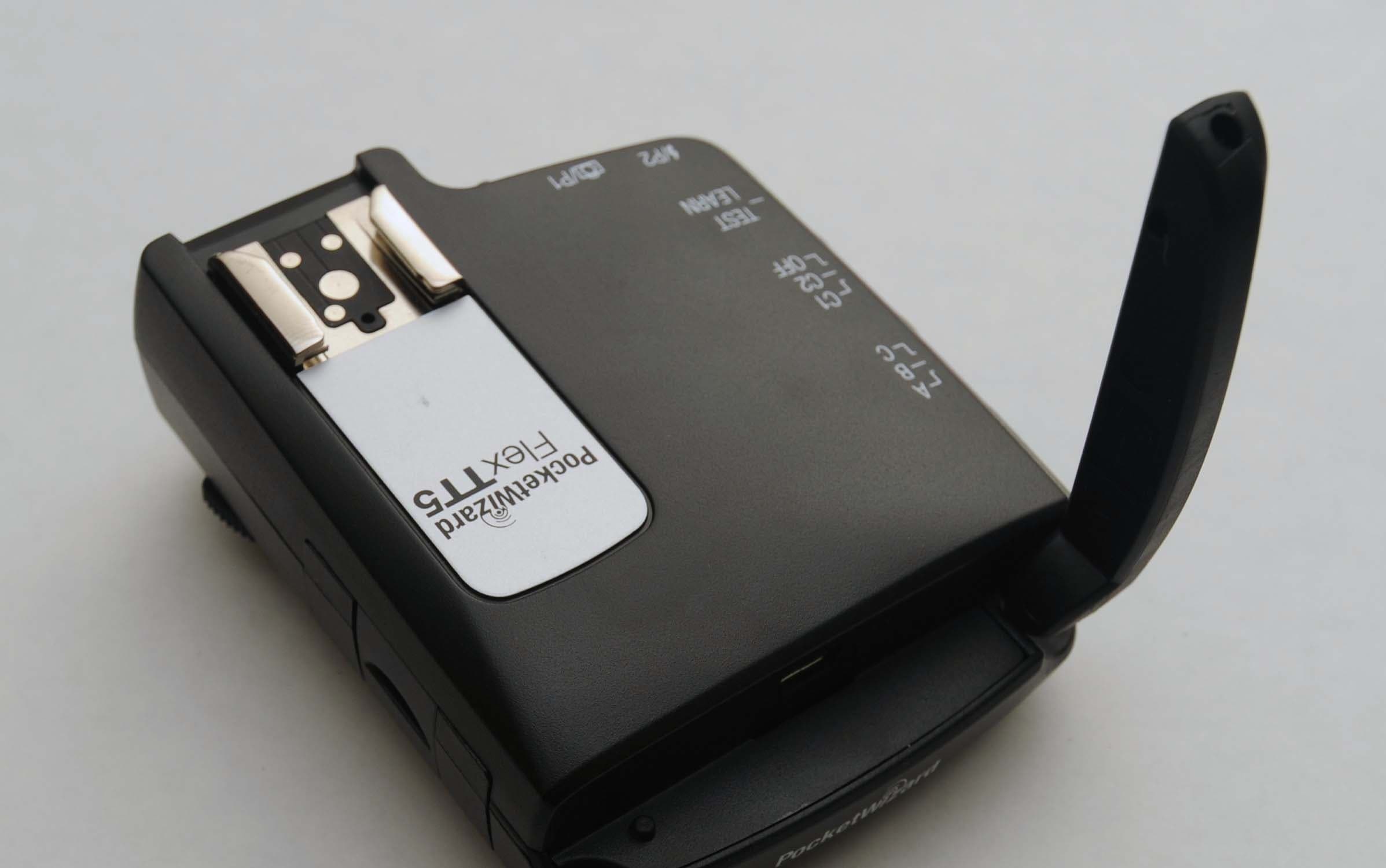
KDS-PW3-008
Dec 08, 2010Remote Flash Control Transceiver
Equipment Class
DSR - Part 15 Remote Control/Security Device Transceiver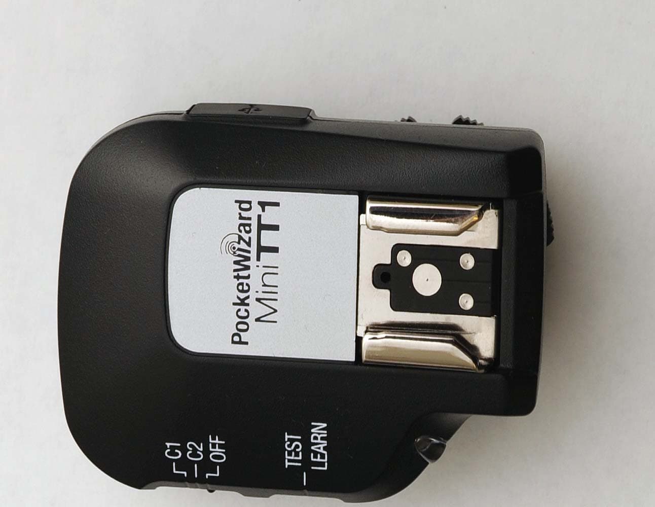
KDS-PW3-007
Dec 08, 2010Remote Flash Control Transceiver
Equipment Class
DSR - Part 15 Remote Control/Security Device Transceiver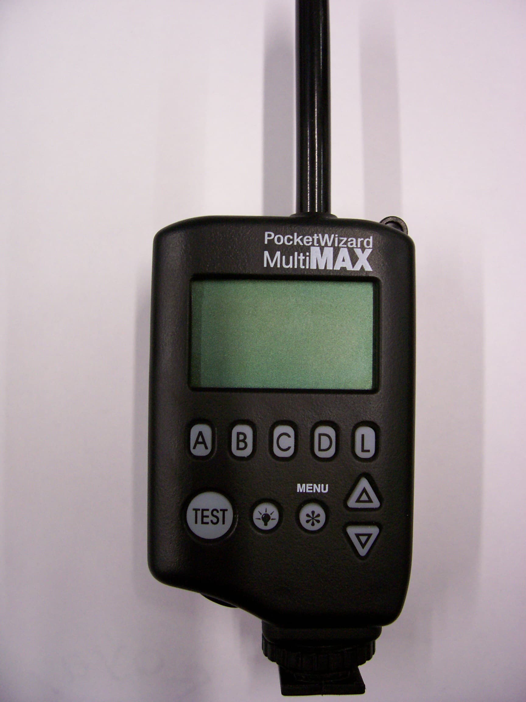
KDS-PW2-101
Jan 07, 2008Remote Flash Control Transceiver
Equipment Class
DSR - Part 15 Remote Control/Security Device Transceiver