KDS-PW3-008Remote Flash Control Transceiver
Lab Partners Associates Inc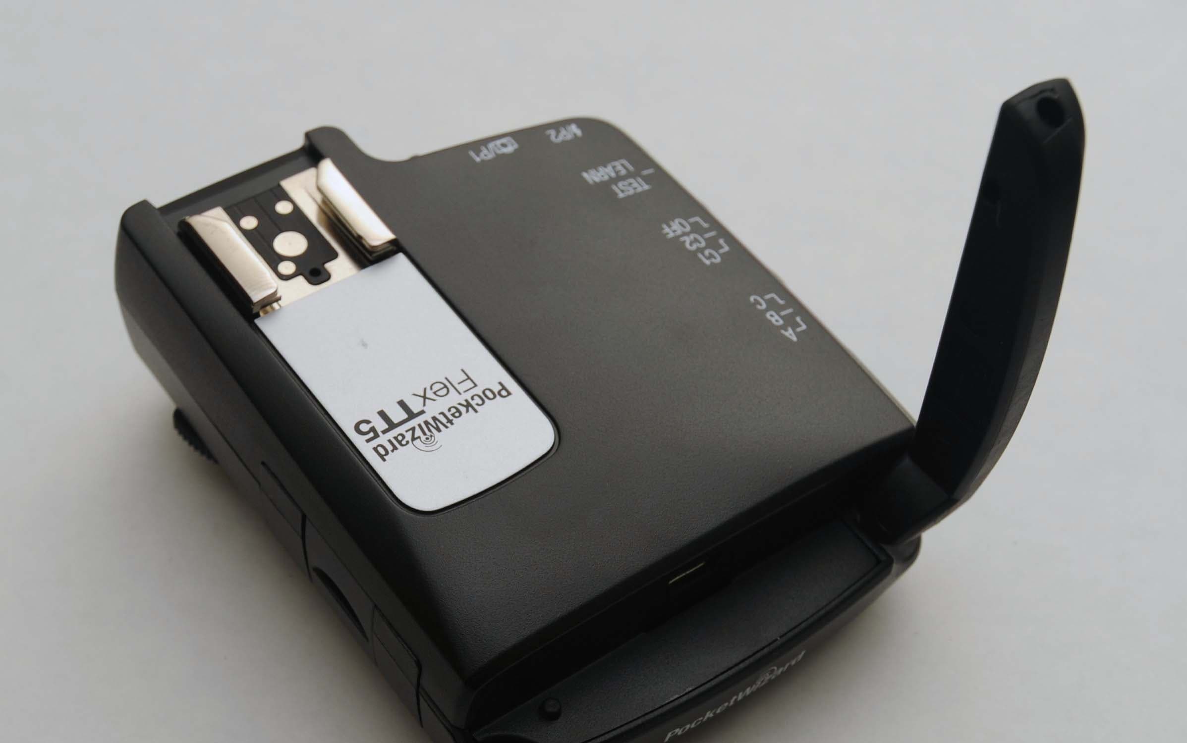
Click to zoom
Application Details
- Equipment Class
- DSR - Part 15 Remote Control/Security Device Transceiver
- Date of Grant
- Dec 08, 2010
- Application Purpose
- Original Equipment
- Date of Application
- Dec 08, 2010
- Equipment Note
- Remote Flash Control Transceiver
- Frequency Range
- 340.00000000 - 354.00000000
- Company
- Lab Partners Associates Inc
- Country
- United States
Documents & Files
Document Text
Text extracted from the exhibit documents filed with the FCC. Open a document above to read the original.
Users Manual
a Quick Guide for Nikon 340.00 – 354.00 MHz, US FCC/IC 433.42 – 434.42 MHz, CE MAKE IT POSSIBLE ™ IMPORTANT: US FCC/Canada frequency radios are NOT compatible with CE frequency radios or Japan frequency radios and vice versa. For more information on frequency, please go to: www.PocketWizard.com/wheretobuy/frequency Please read this Quick Guide thoroughly before operating. Visit www.PocketWizard.com/support to download extended documentation and the PocketWizard Utility. All information in this Quick Guide is subject to change. This PocketWizard radio runs on powerful software called ControlTL ® (Control The Light ™ ). It can be configured for your specific needs using the PocketWizard Utility which can be downloaded at: www.PocketWizard.com/support/downloads. Be sure ALL your PocketWizard ControlTL radios, including this one, are updated to the latest firmware for proper functionality. Power on any connected equipment from the top down: Flash, then radio, then camera. All equipment should be turned OFF when making connections or unwanted triggering may occur. READ ME FIRST: Locking Ring Configuration/Channel 1 Configuration/Channel 2 Power Off Internal Antenna TEST/LEARN Button Battery Compartment (on bottom) Mini-USB Connector (on side) Nikon-style Hot Shoe Status LED a PocketWizard recommends powering your Speedlights with high-capacity rechargeable batteries. If operation is not optimal, check Speedlight batteries first. Review product manuals for your camera and flash system. For most basic functions when using Nikon’s system or PocketWizard radios, operation is identical. Yo u may use a FlexTT5 as a transmitter instead of a MiniTT1 in all scenarios. Make sure all PocketWizard radios are set to the same PocketWizard channel. PocketWizard channels are used instead of Nikon channels. See Learn Mode section. Locking Ring Batteries 2 AA [IEC:LR6] Adjustable Antenna Lanyard Loop Mini-USB Connector (behind antenna) 1/4-20 Mount (on bottom) Remote Flash Triggering Port Remote Camera Triggering Port Nikon-style Hot Shoe Status LED TEST/LEARN Button Configuration/Channel 1 Configuration/Channel 2 Power Off Zone Switch Basic Wireless i-TTL: MiniTT1 FlexTT5 No flash on Camera 1. Slide MiniTT1 Transmitter onto camera. 2. Slide Speedlight onto remote FlexTT5 Transceiver. Set the Speedlight for standard i-TTL mode (not REMOTE or MASTER). Repeat for each remote Speedlight. All remote i-TTL Speedlights will be treated as one zone of light. 3. Make sure all your PocketWizard radios are on the same channel and take pictures normally. This mode is like using the SU-800 in TTL Commander mode, or the SB-800 or SB-900 as MASTER in Advanced Wireless Lighting TTL Mode with master flash cancelled and remote group A selected as TTL with 0.0 FEC. Basic Wireless i-TTL: MiniTT1 FlexTT5 Flash on Camera 1. Slide MiniTT1 Transmitter onto camera. 2. Slide Nikon Speedlight onto MiniTT1 radio. Set the Speedlight for standard i-TTL mode. 3. Slide Speedlight onto remote FlexTT5 Transceiver. Set the Speedlight for standard i-TTL mode (not REMOTE or MASTER). Repeat for each remote Speedlight. All remote i-TTL Speedlights will be treated as one zone of light. 4. Make sure all PocketWizard radios are on the same channel and take pictures normally. i-TTL a Advanced Wireless i-TTL: MiniTT1 FlexTT5 Flash on Camera 1. Slide MiniTT1 Transmitter onto camera. 2. Slide Nikon SB-800 or SB-900 Speedlight onto MiniTT1 radio. Set Speedlight for MASTER = ON. Enable remote groups/zones per flash instructions. Nikon SU-800 Wireless Speedlight Commander may also be used. 3. Set remote FlexTT5 radio to desired Nikon remote group/zone (A, B, C) using FlexTT5 zone switch. 4. Slide Speedlight onto remote FlexTT5 Transceiver. Set Speedlight for standard i-TTL mode (not REMOTE or MASTER). Repeat for each remote Speedlight. All remote i-TTL Speedlights on same FlexTT5 group/zone will be treated as one zone of light. 5. Adjust flash output level compensation using MASTER Speedlight flash controls. 6. Make sure all your PocketWizard radios are on the same channel and take pictures normally. IMPORTANT: Nikon Speedlights set to REMOTE = ON and connected to remote FlexTT5 radios will not function properly as remotes. Turn off REMOTE or MASTER for your remote Speedlights. Set desired Nikon remote group/zone via remote FlexTT5 zone switch. PocketWizard channel is used instead of Nikon channel. ISO, aperture, flash exposure compensation (FEC), and other settings will work with exposure normally via the PocketWizard ControlTL system. MiniTT1 Plus II, MultiMAX, Integrated, or FlexTT5 connected to manual flash Remote flash with or without i-TTL flash on camera 1. Slide MiniTT1 Transmitter onto camera. 2. If desired, slide Nikon i-TTL Speedlight onto MiniTT1 radio. 3. Make sure all your PocketWizard radios are on the same channel and take pictures normally. Note: Manual remote flashes are not calculated as part of the i-TTL exposure. Adjust your exposure or FEC to compensate accordingly. Use PocketWizard Utility to engage HyperSync ™ and explore faster than X-sync shutter speeds. Visit www.PocketWizard.com for more information. Learn about the AC3 ZoneController, PowerTracking, and controlling your Speedlights and select studio flashes by reading the extended documentation for the following PocketWizard radios and accessories: • AC3 ZoneController for Nikon (coming soon) • PowerST4 for Elinchrom • AC9 AlienBees Adapter for Nikon (coming soon) Manual FlashManual Flash a Channels can be set via PocketWizard Utility (recommended) or taught from any PocketWizard transmitter using Learn Mode. Learn Mode is not required for normal operation of the radios. IMPORTANT: Hold radios at least 2 feet apart when teaching/learning. 1. Turn MiniTT1 or FlexTT5 radio ON and select channel to be taught: C.1 or C.2. 2. Press and hold TEST for several seconds until LED blinks amber, then release TEST. 3. Quickly press and hold TEST on teaching transmitting radio (MiniTT1, FlexTT…
Text truncated - open the document above for the full version.
Users Manual
DOWNLOAD UTILITY: UPDATE FIRMWARE: REGISTER ONLINE: Please Read [seriously... you'll thank us later...] Be sure ALL your PocketWizard ControlTL radios, including this one, are updated to the latest firmware for proper functionality. This can be done via the PocketWizard Utility. ControlTL software is designed to be "Future Proof" and will be upgraded from time-to-time. Please register your product by going to PocketWizard.com/support/register and you will be notified when updates are available. Your new PocketWizard radio runs on powerful software we call ControlTL ® (Control The Light ™ ) which can be configured to your specific needs using the PocketWizard Utility. You can download this utility from PocketWizard.com/support/downloads. Thank you for purchasing a PocketWizard radio slave, the most advanced photographic wireless control system available. To get the most out of your new radio, please spend time on PocketWizard.com/support where you will find information on all aspects of your new PocketWizard radio slave. WARNING Changes or modifications to this unit not expressly approved by the party responsible for compliance could void the user’s authority to operate this equipment. NOTE: This equipment has been tested and found to comply with the limits for a Class B digital device, pursuant to Part 15 of the FCC rules. These limits are designed to provide reasonable protection against harmful interference in a residential installation. This equipment generates, uses, and can radiate radio frequency energy, and, if not installed and used in accordance with the instructions, may cause harmful interference to radio communications. However, there is no guarantee that interference will not occur in a particular installation. If this equipment does cause harmful interference to radio or television reception, which can be determined by turning the equipment off and on, the user is encouraged to try to correct the interference by one or more of the following measures: 1. Reorient or relocate the receiving antenna. 2. Increase the separation between the equipment and the receiver. 3. Consult the dealer or an experienced radio or television technician for help. This device complies with Part 15 of the FCC rules and also with RSS-210 of Industry Canada. Operation is subject to the following two conditions: (1) This device may not cause harmful interference, and (2) This device must accept any interference received, including interference that may cause undesired operation. MiniTT1 for Canon FCC ID Number: KDS-PW3-004 FlexTT5 for Canon FCC ID Number: KDS-PW3-005 MiniTT1 for Canon CANADA IC: 2170A-PW3004 FlexTT5 for Canon CANADA IC: 2170A-PW3005 MiniTT1 for Nikon FCC ID Number: KDS-PW3-007 FlexTT5 for Nikon FCC ID Number: KDS-PW3-008 MiniTT1 for Nikon CANADA IC: 2170A-PW3007 FlexTT5 for Nikon CANADA IC: 2170A-PW3008 The FCC wants you to know: LPF680v1.8 July 2010 MAKE IT POSSIBLE ™
Cover Letter(s)
Nov 10th, 2010 Retlif Testing Laboratories 101 New Boston Road Goffstown, NH 03045 Attn: Scott Wentworth Ref: AGENT AUTHORIZATION/ANTI-DRUG ABUSE CERTIFICATION Dear Scott, Lab Partners Associates, Inc. (dba LPA Design) hereby authorizes Retlif Testing Laboratories, 101 New Boston Road, Goffstown, NH 03045 to act as our agent in all matters pertaining to FCC and Industry Canada Certification of our PocketWizard FlexTT5. LPA Design (The Applicant) certifies that neither LPA Design nor any party to the application is subject to denial of Federal benefits, that include FCC benefits pursuant to Section 5301 of the Anti-Drug Abuse Act of 1988, 21 U.S.C. 862 because of a conviction for possession or distribution of a controlled substance. See 47CFR 1.2002(b) for the definition of a “party” for these purposes. Sincerely, James Clark VP Research and Development LPA Design
Test Report
Retlif Testing Laboratories, Test Report R-5329N-1, Rev. A, LPA Design, Inc. FCC ID: KDS-PW3-008, IC: 2170A-PW3008 Technical Information APPLICANT MANUFACTURER Name: LPA Design, Inc. Name: LPA Design, Inc. Address: 41 IDX Drive, Suite 265 Address: 41 IDX Drive, Suite 265 City, State, Zip: South Burlington, VT 05403 City, State, Zip:South Burlington, VT 05403 TEST SPECIFICATION: FCC Rules and Regulations Part 15, Subpart C, Section 15.231 Radio Standards Specification, RSS-210, Issue 7, June, 2007 and RSS-GEN, Issue 2, June 2007 TEST PROCEDURE: ANSI C63.4:2003 Test Sample Description TEST SAMPLE: PocketWizard Flex TT5 Transceiver BRANDNAME(s): PocketWizard MODEL: TT5-N-US FCC ID: KDS-PW3-008 IC: 2170A-PW3008 TYPE: Remote Control Flash Transceiver POWER REQUIREMENTS: 3VDC via two AA batteries FREQUENCY OF OPERATION: 340 MHz to 354 MHz Support Equipment Description Manufacturer Model Number Serial Number Digital Camera Fujifilm Corp. Finepix S5 Pro 73A01917 Flash/Light Nikon Speedlight SB-600 N/A Page 2 of 45 Retlif Testing Laboratories, Test Report R-5329N-1, Rev. A, LPA Design, Inc. FCC ID: KDS-PW3-008, IC: 2170A-PW3008 Tests Performed The test methods performed on the PocketWizard MiniTT1 Transceiver are shown below: FCC Part 15, Subpart C Industry Canada RSS-210 Issue 7, June 2007 Industry Canada RSS-GEN Issue 2, June 2007 Test Method 15.231(b) A1.1.2(1) N/A Field Strength of Emissions 15.231(b)(2) A1.1.2(2) 4.5 Duty Cycle Determination 15.231(b)(3) A1.1.2(3) N/A Field Strength of Spurious Emissions 15.231(c) A1.1.3 N/A Bandwidth of Emission N/A N/A 4.10 Receiver Spurious Emissions General Test Requirements 1. The measurement procedures of ANSI C63.4:2003 were utilized as specified in FCC Part 15, Subpart C, Section 15.31(a)(3) and IC RSS-GEN Section 4.1. 2. All radiated emissions measurements were performed on an Open Area Test Site (OATS), listed with the FCC and IC, in accordance with FCC Section 15.31(d) and IC Section 4.2. 3. The level of the fundamental field strength was recorded with a new battery installed in the EUT, in accordance with FCC Section 15.231(e) and IC Section 4.3(e). 4. All measurements were performed at the specified 3 meter test distance as required by FCC Section 15.31(f) and IC Section 7.25. 5. The EUT was rotated throughout 360 degrees for all radiated emissions measurements as specified in FCC Section 15.31(f)(5) and IC Section 4.3(h). 6. All readily accessible EUT controls were adjusted in such a manner as to maximize the level of emissions in accordance with FCC Section 15.31(g) and IC Section 4.3(h). 7. Appropriate accessories were attached to all EUT ports during the performance of radiated emissions measurements as required by FCC Section 15.31(i) and IC Section 4.3(d). 8. The EUT operated over the frequency range of 340 MHz to 354 MHz. A total range of 14 MHz. Testing was performed with the device operating at a. 3 frequencies, 1 at the top, 1 in the middle and 1 at the bottom of the range of operation in accordance with FCC Section 15.31(m) and IC Section 4.3(f)(g). 9. The frequency spectrum was investigated from the lowest frequency generated in the device up to the 10 th harmonic of the highest fundamental frequency in accordance with FCC Section 15.33(a)(1) and IC Section 4.9. 10. All measurements were taken with a peak detector function as specified in FCC Section 15.35(a) and IC Section 4.4. The duty cycle, calculated in accordance with FCC Section 15.35(c) and IC Section 4.5, was applied to the peak readings in order to obtain the average value of emissions. The peak value of emissions was verified to meet the 20 dB requirement of FCC Section 15.35(b) and IC Section 7.2.1. Page 3 of 45 Retlif Testing Laboratories, Test Report R-5329N-1, Rev. A, LPA Design, Inc. FCC ID: KDS-PW3-008, IC: 2170A-PW3008 Certification and Signatures We certify that this report is a true representation of the results obtained from the tests of the equipment stated. We further certify that the measurements shown in this report were made in accordance with the procedures indicated and vouch for the qualifications of all Retlif Testing Laboratories personnel taking them. Scott Wentworth Branch Manager NVLAP Approved Signatory Todd Hannemann Laboratory Supervisor iNARTE Certified ATL-0255-T Non-Warranty Provision The testing services have been performed, findings obtained and reports prepared in accordance with generally accepted laboratory principles and practices. This warranty is in lieu of all others, either expressed or implied. Non-Endorsement This test report contains only findings and results arrived at after employing the specific test procedures and standards listed herein. It is not intended to constitute a recommendation, endorsement or certification of the product or material tested. This test report must not be used by the client to claim product endorsement by NVLAP or any agency of the U.S. Government. Page 4 of 45 Retlif Testing Laboratories, Test Report R-5329N-1, Rev. A, LPA Design, Inc. FCC ID: KDS-PW3-008, IC: 2170A-PW3008 Revision History Revisions to this document are listed below; the latest revised document supersedes all previous issues of this document. Revision Date Pages Affected - November 22, 2010 Original Release A December 8, 2010 2, 9 Page 5 of 45 Retlif Testing Laboratories, Test Report R-5329N-1, Rev. A, LPA Design, Inc. FCC ID: KDS-PW3-008, IC: 2170A-PW3008 Requirements and Test Results Requirement: FCC Section 15.231(a) - Periodic operation in the band 40.66 - 40.7 MHz and above 70 MHz The provisions of this Section are restricted to periodic operation within the band 40.66-40.7 MHz and above 70 MHz. Except as shown in Paragraph (e) of this Section, the intentional radiator is restricted to the transmissions of a control signal such as those used with alarm systems, door openers, remote switches, etc. Continuous transmissions, voice, video and the radio control of toys are not permitted. Data is permitted to be sent with a control sign…
Text truncated - open the document above for the full version.
Test Setup Photos
Retlif Testing Laboratories, Test Report R-5329N-1, LPA Design, Inc. FCC ID: KDS-PW3-008, IC: 2170A-PW3008 Test Configuration Page 13 of 43 Retlif Testing Laboratories, Test Report R-5329N-1, LPA Design, Inc. FCC ID: KDS-PW3-008, IC: 2170A-PW3008 Horizontal Antenna Polarization, 30 to 1000 MHz Vertical Antenna Polarization, 30 to 1000 MHz Page 14 of 43
Contact Information
Applicant
Bryan Bourgeois(General Manager)
Technical Contact
RetlifScott Wentworth
[email protected]6034974600
101 New Boston Road · Goffstown, New Hampshire · United States
Non-Technical Contact
RetlifScott Wentworth
[email protected]6034974600
Test Firm
Retlif Testing LaboratoriesScott Wentworth
Technical Specifications
| # | Rule Parts | Frequency Range | Power Output |
|---|---|---|---|
| 1 | 15.231 | 340 MHz - 354 MHz | - |
Other Applications from Lab Partners Associates Inc

KDS-PWX-100
Feb 10, 2013Remote Flash Control Transceiver
Equipment Class
DSR - Part 15 Remote Control/Security Device Transceiver
KDS-PW3-100
Mar 18, 2012Remote Flash Control Transceiver
Equipment Class
DSR - Part 15 Remote Control/Security Device Transceiver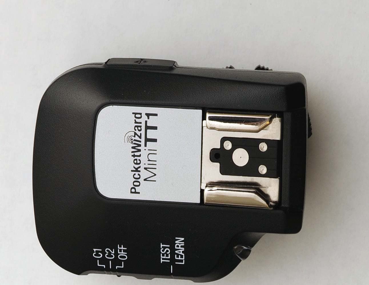
KDS-PW3-007
Dec 08, 2010Remote Flash Control Transceiver
Equipment Class
DSR - Part 15 Remote Control/Security Device Transceiver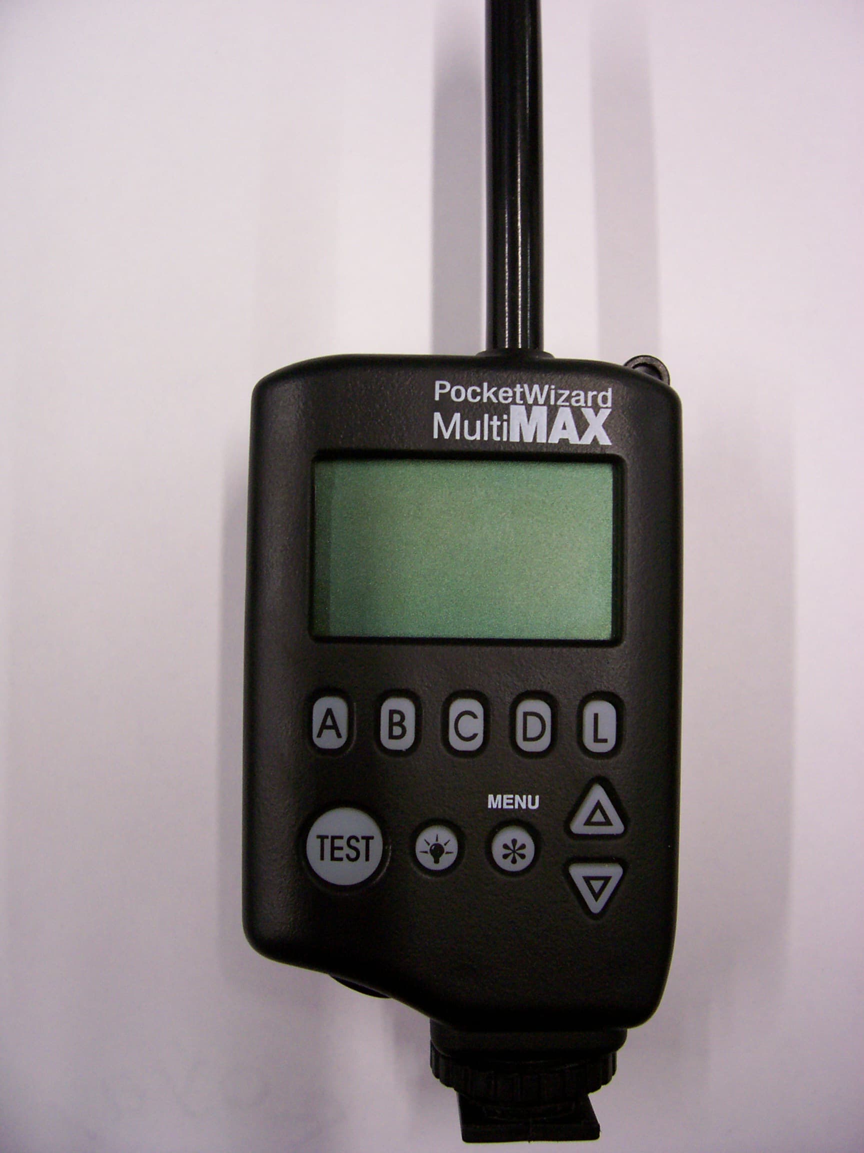
KDS-PW2-101
Jan 07, 2008Remote Flash Control Transceiver
Equipment Class
DSR - Part 15 Remote Control/Security Device Transceiver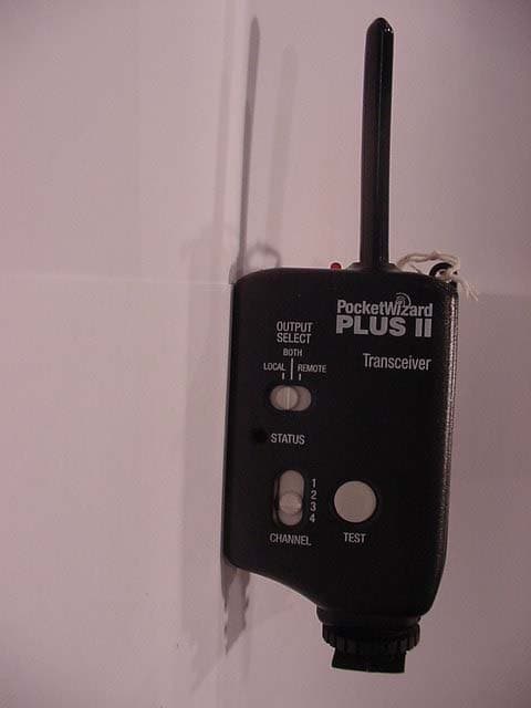
KDS-PW2-003
Jun 14, 2006Remote Control Transmitter
Equipment Class
DSR - Part 15 Remote Control/Security Device Transceiver