KDS-PW3-100Remote Flash Control Transceiver
Lab Partners Associates Inc
Click to zoom
Application Details
- Equipment Class
- DSR - Part 15 Remote Control/Security Device Transceiver
- Date of Grant
- Mar 18, 2012
- Application Purpose
- Original Equipment
- Date of Application
- Mar 18, 2012
- Equipment Note
- Remote Flash Control Transceiver
- Frequency Range
- 340.00000000 - 354.00000000
- Company
- Lab Partners Associates Inc
- Country
- United States
Documents & Files
Document Text
Text extracted from the exhibit documents filed with the FCC. Open a document above to read the original.
Users Manual
Quick Guide 340.00 - 354.00 MHz, US FCC/IC 433.42 - 434.42 MHz, CE The Plus III is a radio transceiver, capable of acting as a transmitter or receiver for triggering remote flashes and cameras. It requires at least one other PocketWizard radio for wireless triggering. It can be connected to almost any remote flash or camera with the proper connecting cable. See the cable finder at PocketWizard.com to find the correct cables for your flashes and cameras. • Please read this Quick Guide thoroughly before operating. • Visit wiki.PocketWizard.com for complete operating information. IMPORTANT: US FCC/Canada frequency radios are NOT compatible with CE frequency radios and vice versa. For more information on frequency, please go to: PocketWizard.com/ wheretobuy/frequency Internal Antenna (PG. 12) Backlit LCD Test Button (2 Stage Trigger) (PG. 12) Power On/Off and MODE Button (PG. 5) Zone Toggle Buttons (A, B, C, D) (PG. 11) Status LED (PG. 12) Channel Up/Down Buttons (PG. 11) Hot Shoe with Locking Ring READ ME FIRST: Transceiver • All equipment should be turned OFF when making connections. Otherwise unwanted triggering or erratic behavior may occur. • If operation is erratic, check batteries in all equipment first. • You will need a PocketWizard Transceiver/Receiving PocketWizard radio for each remote flash. • Set all radios to the same channel. INCLUDED IN BOX: Lanyard Loop USB Connector Flash/Camera Port Battery Door Latch Battery Door (PG. 4) 1/4 - 20 Mount Transceiver • Plus III Transceiver • PC Sync Cable • 3.5mm (1/8” Miniphone) Cable • 6.35mm (1/4” Phone) Adapter • Lanyard • Quick Guide 3 Transceiver Battery Level Channel Triggering Mode Half/Full Press Indicator Selected Zones Illustrations FPO • Always turn OFF all equipment (PocketWizard radios, electronic flashes, cameras, etc.) before making connections or replacing batteries. • The Plus III will operate reliably using almost any pair of ~1.5 volt AA (IEC:LR6) batteries. Rechargeable batteries will work, though operation time may be reduced and battery level display may not be as accurate. See wiki.PocketWizard.com for more information. Using your Connecting: Connect a Plus III to your camera via the hot shoe. This will be your transmit- ting radio. Connect a Plus III to each of your remote flashes using a connecting cable (see PocketWizard.com/support/cable_finder). These will be your receiving radios. Powering On: Install batteries noting the proper polarity. To turn on your Plus III, hold down the Power On/Off and MODE Button <> for about two seconds. The Status LED blinks green every few seconds to indicate normal operation. It will blink red in sync with a trigger. Hold down the Power On/Off and MODE Button for about two seconds to turn off your Plus III. Channels & Zones: Your Plus III needs to be on the same channel as other PocketWizard radios. Channels can be set via the Plus III’s Channel Up/Down Buttons <>. Any transmitting PocketWizard radio can trigger a receiving Plus III and a Plus III can trigger any receiving PocketWizard radio. When using Channels 17-32, you can specify Zones A, B, C, and D. See “Channels and Zones” section for more info. Plus III Transceiver Basics 5 NOTE: The Plus III slides into hot shoe with the LCD screen facing the side of the camera. See diagram below. Connect the transmitting Plus III to camera hot shoe and tighten the locking ring Connect the receiving Plus III to your flashes with the appropriate sync cable Triggering a Remote Flash with your Plus ® III Transceiver Remote Flash Triggering 1. Connect a Plus III to your remote flash via the appropriate sync cable. 2. Attach a Plus III to your camera’s hot shoe. You may also connect the Plus III radio to your camera’s PC sync port using the included cable. 3. Select the Channel and Zone A, B, C, or D via Channel Up/Down Buttons <> and Zone Toggle Buttons. Set any other PocketWizard radios to a matching Channel and Zone. (See the “Using Zones” section for more information) 4. Take pictures normally at or below your camera’s X-Sync speed. Momentarily pressing the TEST button will test trigger the flash. Camera with Plus III in Hot Shoe (Transmitting) Any PocketWizard receiver connected to remote flash (Receiving) NOTE: With the transmitting and receiving PocketWizard radios set to the same channel and zone, remote flashes will be synchronized with the camera. To find the right sync cable for your flash visit the Cable Finder at PocketWizard.com/support/cable_finder 7 Remote Camera Triggering Triggering a Remote Camera with your Plus III Transceiver 1. Connect a Plus III to your remote camera via the appropriate remote camera cable. 2. Select the Channel and Zone A, B, C, or D via the Channel Up/Down Buttons <> and Zone Toggle Buttons. 3. Press the TEST button on the PocketWizard radio in your hands. The remote camera will trigger. If the PocketWizard radio in your hands is also a Plus III, you can pre-release the remote camera by pressing the TEST button half way <>. This wakes up the camera and lets it respond more quickly and consistently. It can also engage autofocus. To read more about remote camera triggering visit the PocketWizard wiki at http://wiki.PocketWizard.com/ Camera in hand OR Plus III (Transmitting) Remote Camera (Receiving) NOTE: The transmitting PocketWizard radio triggers the receiving PocketWizard radio, which fires the remote camera via a remote camera cable. To find the right remote camera cable for your equipment visit the Cable Finder at PocketWizard.com/support/cable_finder Using Auto-Relay Mode 1. Set the transmitting PocketWizard radio in your hands to a desired channel and zone. 2. Set the relaying Plus III for your remote camera to the same channel as the radio in your hands and set Triggering Mode to TxRx. 3. Connect the relaying Plus III’s Flash/Camera port to the remote camera triggering port of the camera via a remote camera cable. 4. Slide the relaying Plus III into your remote camera’s hot shoe. 5. Connect you…
Text truncated - open the document above for the full version.
ID Label/Location Info
0.005in 10941 FCC LABEL WITHOUT THE WRITTEN PERMISSION OF 5 4 3 0.010in X.XXX 1 1:1 X.X DEG 2 DIMENSIONS APPLY TO FINISHED PART INTERPRET PER ASME Y14.5, 1994 LOCATION 10941 PLUS III SCALE DWG. NO. A LPA DESIGN IS PROHIBITED. www.LPADesign.com 1 DEG SIZE DIMENSIONS ARE IN INCHES (MILLIMETERS) SHEET 1 OF 1 LPA Design TITLE TOLERANCES ARE: X.X 0.050in X.XX PROPRIETARY AND CONFIDENTIAL THE INFORMATION CONTAINED IN THIS DRAWING IS THE SOLE PROPERTY OF LPA DESIGN, BURLINGTON, VT. ANY REPRODUCTION IN PART OR AS A WHOLE C:\Users\mark.LPA\Documents\Solidworks Vault Local Copy\ D09 REV. DESCRIPTION DATE BY 01 INITIAL DESIGN Jan 4, 2011 MB FCC/IC label goes here
Test Report
Retlif Testing Laboratories, Test Report R-5548N-1, LPA Design, Inc. FCC ID: KDS-PW3-100, IC: 2170A-PW3100 Technical Information MANUFACTURER APPLICANT Name: Lab Partners Associates, Inc. Name: Lab Partners Associates, Inc. Address: 21 Gregory Drive, Suite 140 Address: 21 Gregory Drive, Suite 140 City, State, Zip: South Burlington, VT 05403 City, State, Zip: South Burlington, VT 05403 TEST SPECIFICATION: FCC Rules and Regulations Part 15, Subpart C, Section 15.231 Radio Standards Specification, RSS-210, Issue 8, December 2010 and RSS-GEN, Issue 3, December 2010 TEST PROCEDURE: ANSI C63.4:2003 Test Sample Description TEST SAMPLE: PocketWizard Plus III Transceiver BRANDNAME(s): PocketWizard MODEL: P3-FCC FCC ID: KDS-PW3-100 IC : 2170A-PW3100 TYPE: Wireless Flash Control Transceiver POWER REQUIREMENTS: 3VDC via 2 internal AA batteries FREQUENCY OF OPERATION: 340MHz to 354MHz SUPPORT EQUIPMENT: The PocketWizard Plus III Transceiver was tested while mounted via hot shoe connector on a Canon Rebel XSi Digital Camera, Model DS126181, Serial #0870319069. PURPOSE: The purpose of this test program was to demonstrate compliance of the P3-FCC PocketWizard Plus III Transceiver to FCC Part 15.231 and RSS-210, Annex 1. Page 2 of 58 Retlif Testing Laboratories, Test Report R-5548N-1, LPA Design, Inc. FCC ID: KDS-PW3-100, IC: 2170A-PW3100 Tests Performed The test methods performed on the P3-FCC Pocket Wizard Plus III Transceiver are shown below: FCC Part 15, Subpart C Industry Canada RSS-210 Issue 8, December 2010 Industry Canada RSS-GEN Issue 3, December 2010 Test Method 15.231(b) A1.1.2(1) N/A Field Strength of Fundamental Emissions 15.231(b)(2) A1.1.2(2) 4.5 Duty Cycle Determination 15.231(b)(3) A1.1.2(3) N/A Field Strength of Spurious Emissions 15.231(c) A1.1.3 N/A Bandwidth of Emissions N/A N/A 4.10 Receiver Spurious Emissions General Test Requirements 1. The measurement procedures of ANSI C63.4:2003 were utilized as specified in FCC Part 15, Subpart C, Section 15.31(a)(3) and IC RSS-GEN Section 4.1. 2. All radiated emissions measurements were performed on an Open Area Test Site (OATS), listed with the FCC and IC, in accordance with FCC Section 15.31(d) and IC Section 4.2. 3. The level of the fundamental field strength was recorded with a new battery installed in the EUT, in accordance with FCC Section 15.231(e) and IC Section 4.3(e). 4. All measurements were performed at the specified 3 meter test distance as required by FCC Section 15.31(f) and IC Section 7.25. 5. The EUT was rotated throughout 360 degrees for all radiated emissions measurements as specified in FCC Section 15.31(f)(5) and IC Section 4.3(h). 6. All readily accessible EUT controls were adjusted in such a manner as to maximize the level of emissions in accordance with FCC Section 15.31(g) and IC Section 4.3(h). 7. Appropriate accessories were attached to all EUT ports during the performance of radiated emissions measurements as required by FCC Section 15.31(i) and IC Section 4.3(d). 8. The EUT operated over the frequency range of 340 MHz to 354 MHz. A total range of 14 MHz. Testing was performed with the device operating at a. 3 frequencies, 1 at the top, 1 in the middle and 1 at the bottom of the range of operation in accordance with FCC Section 15.31(m) and IC Section 4.3(f)(g). 9. The frequency spectrum was investigated from the lowest frequency generated in the device up to the 10 th harmonic of the highest fundamental frequency in accordance with FCC Section 15.33(a)(1) and IC Section 4.9. 10. All measurements were taken with a peak detector function as specified in FCC Section 15.35(a) and IC Section 4.4. The duty cycle, calculated in accordance with FCC Section 15.35(c) and IC Section 4.5, was applied to the peak readings in order to obtain the average value of emissions. The peak value of emissions was verified to meet the 20 dB requirement of FCC Section 15.35(b) and IC Section 7.2.1. Page 3 of 58 Retlif Testing Laboratories, Test Report R-5548N-1, LPA Design, Inc. FCC ID: KDS-PW3-100, IC: 2170A-PW3100 Certification and Signatures We certify that this report is a true representation of the results obtained from the tests of the equipment stated. We further certify that the measurements shown in this report were made in accordance with the procedures indicated and vouch for the qualifications of all Retlif Testing Laboratories personnel taking them. Scott Wentworth Branch Manager NVLAP Approved Signatory Todd Hannemann Laboratory Supervisor iNARTE Certified ATL-0255-T Non-Warranty Provision The testing services have been performed, findings obtained and reports prepared in accordance with generally accepted laboratory principles and practices. This warranty is in lieu of all others, either expressed or implied. Non-Endorsement This test report contains only findings and results arrived at after employing the specific test procedures and standards listed herein. It is not intended to constitute a recommendation, endorsement or certification of the product or material tested. This test report must not be used by the client to claim product endorsement by NVLAP or any agency of the U.S. Government. Page 4 of 58 Retlif Testing Laboratories, Test Report R-5548N-1, LPA Design, Inc. FCC ID: KDS-PW3-100, IC: 2170A-PW3100 Revision History Revisions to this document are listed below; the latest revised document supersedes all previous issues of this document. Revision Date Pages Affected - March 2, 2012 Original Release Page 5 of 58 Retlif Testing Laboratories, Test Report R-5548N-1, LPA Design, Inc. FCC ID: KDS-PW3-100, IC: 2170A-PW3100 Requirements and Test Results Requirement: FCC Section 15.231(a) - Periodic operation in the band 40.66 - 40.7 MHz and above 70 MHz The provisions of this Section are restricted to periodic operation within the band 40.66-40.7 MHz and above 70 MHz. Except as shown in Paragraph (e) of this Section, the intentional radiator is restricted to the transmissions of a control signal such as those used with al…
Text truncated - open the document above for the full version.
Test Setup Photos
Retlif Testing Laboratories, Test Report R-5548N-1, LPA Design, Inc. FCC ID: KDS-PW3-100, IC: 2170A-PW3100 Test Configuration X Test Configuration Y Page 35 of 58 Retlif Testing Laboratories, Test Report R-5548N-1, LPA Design, Inc. FCC ID: KDS-PW3-100, IC: 2170A-PW3100 Test Configuration Z Page 36 of 58 Retlif Testing Laboratories, Test Report R-5548N-1, LPA Design, Inc. FCC ID: KDS-PW3-100, IC: 2170A-PW3100 Horizontal Antenna Polarization, 30 to 1000 MHz Vertical Antenna Polarization, 30 to 1000 MHz Page 37 of 58 Retlif Testing Laboratories, Test Report R-5548N-1, LPA Design, Inc. FCC ID: KDS-PW3-100, IC: 2170A-PW3100 Horizontal Antenna Polarization, 1 to 4 GHz Vertical Antenna Polarization, 1 to 4 GHz Page 38 of 58
Contact Information
Applicant
Bryan Bourgeois(General Manager)
Technical Contact
RetlifScott Wentworth
[email protected]6034974600
101 New Boston Rd. · Goffstown, New Hampshire · United States
Non-Technical Contact
RetlifScott Wentworth
[email protected]6034974600
Test Firm
Retlif Testing LaboratoriesScott Wentworth
Technical Specifications
| # | Rule Parts | Frequency Range | Power Output |
|---|---|---|---|
| 1 | 15.231 | 340 MHz - 354 MHz | - |
Other Applications from Lab Partners Associates Inc

KDS-PWX-100
Feb 10, 2013Remote Flash Control Transceiver
Equipment Class
DSR - Part 15 Remote Control/Security Device Transceiver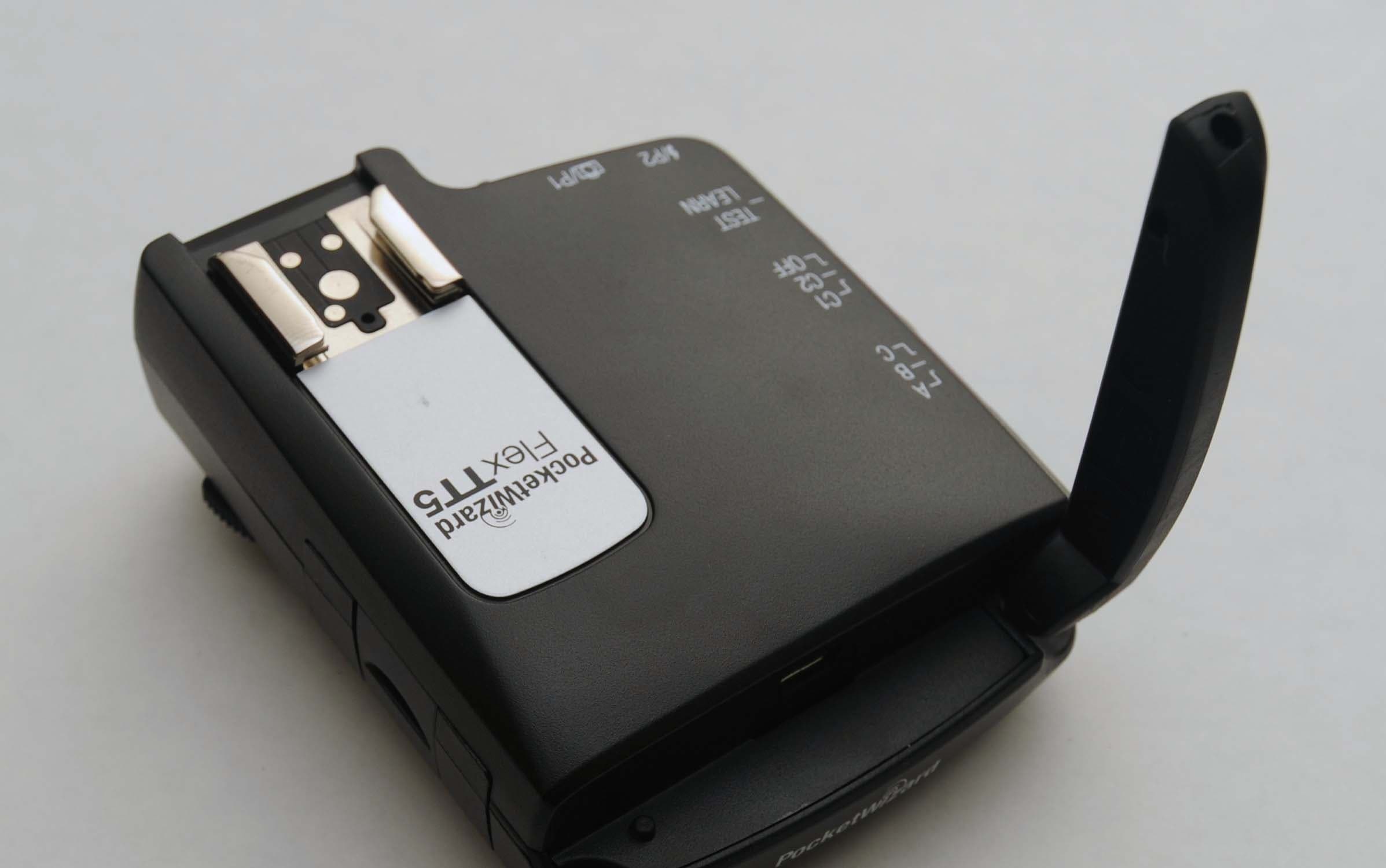
KDS-PW3-008
Dec 08, 2010Remote Flash Control Transceiver
Equipment Class
DSR - Part 15 Remote Control/Security Device Transceiver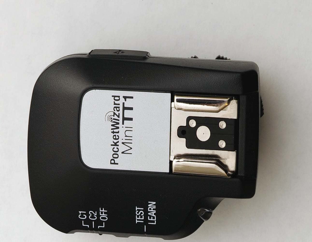
KDS-PW3-007
Dec 08, 2010Remote Flash Control Transceiver
Equipment Class
DSR - Part 15 Remote Control/Security Device Transceiver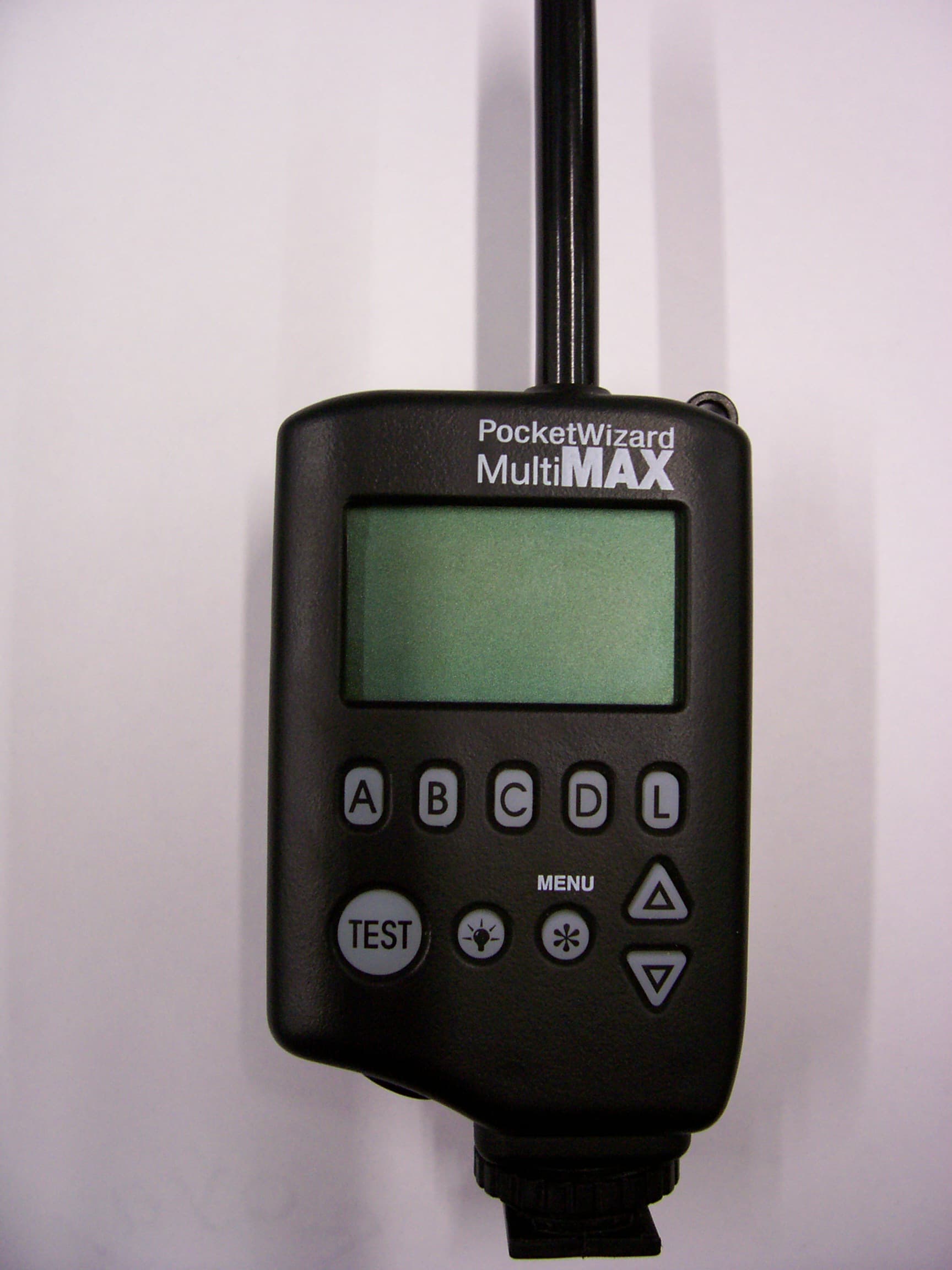
KDS-PW2-101
Jan 07, 2008Remote Flash Control Transceiver
Equipment Class
DSR - Part 15 Remote Control/Security Device Transceiver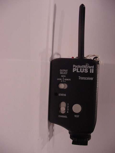
KDS-PW2-003
Jun 14, 2006Remote Control Transmitter
Equipment Class
DSR - Part 15 Remote Control/Security Device Transceiver