KF5ORTOVOXS1Avalanche Transceiver
Ortovox Sportartikel GmbH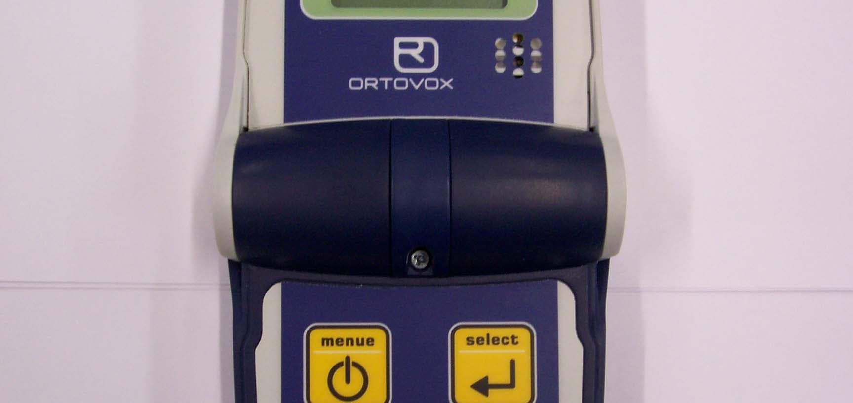
Click to zoom
Application Details
- Equipment Class
- DCD - Part 15 Low Power Transmitter Below 1705 kHz
- Date of Grant
- Apr 03, 2007
- Application Purpose
- Original Equipment
- Date of Application
- Apr 03, 2007
- Equipment Note
- Avalanche Transceiver
- Frequency Range
- 0.45700000 - 0.45700000
- Company
- Ortovox Sportartikel GmbH
- Country
- Germany
Documents & Files
Document Text
Text extracted from the exhibit documents filed with the FCC. Open a document above to read the original.
Users Manual
25 Scanning the avalanche track for transmit- ters and locating each signal quickly and exactlyare the decisive advantages of the ORTOVOX avalanche transceiver S1. An im- mediate search with an avalanche transcei- ver and a rescue using avalanche shovels and a probe that is carried out by the tour parti- cipants themselves offers the best chance of survival for an avalanche victim. When third party help has to be called to the scene it usually arrives too late! Pay attention to the avalanche report and select safe routes. Al- ways take the avalanche transceiver S1 with you together with the necessaryORTOVOX SAFETY PRODUCTSsuch as an avalanche shovel and a probe. Read the S1 operating instructions carefully and practice both the handling of your avalanche transceiver S1 and avalanche search procedures. Information on ORTOVOX products and safety notices can be found on the ORTOVOX web- site at www.ortovox.com Contact us by e-mail at [email protected] ORTOVOX wishes you wonderful, safe tours! CONTENT Operating elements25 Technical data 26 EU Declaration of Conformity26 Quick reference27 Basic avalanche know-how 30 Operating instructions34 Coarse, refined and pinpoint location36 Menue at a glance39 Daily function check40 Locating several avalanche victims 40 Acoustic emergency reception41 Interfernce42 Battery changes42 Protective case and wrist strap42 Guarantee/ service43 Service addresses112 www.ortovox.com Current avalanche warning service information! 1ON/ OFF button (and MENU function button) 2Screen with display of victim location 3Sensor for back- lighting 4Transmission indication lights 5Loudspeaker 6Bottons to release open ENGLISH OPERATING ELEMENTS 3 1 2 10 11 9 8 7 6 5 4 7‘Select’ button for menu and for flagging 8Battery compartment (on rear) 6 4 9Protective case with carrying strap 10Quick lock 11Shoulder strap markings (SILVER) 2726 TECHNICAL DATA DEVICE DESIGNATION:ORTOVOX S1 FUNCTION:digital with acoustic emergency operation CASING: ergonomic, waterproof, impact-resistant DIMENSIONS: 120 x 80 x 30 mm (closed); 215 x 80 x 30 mm (open) FREQUENCY Transmitting:457 kHz +-80 Hz The S1 can receive signals from any standard avalanche transceiver with no limitations DIGITAL RECEPTION RANGE:up to 65 m SEARCH STRIP WIDTH:up to 40 m TEMPERATURE RANGE:-20° C to +45° C POWER SUPPLY: 3 alkaline AAA Mignon 1.5 V LR 03 batteries OPERATING TIME TRANSMITTING:about 250 hours RECEIVING:about 10 hours WEIGHT:approximately 260 g incl. batteries and wrist strap, carrying case approximately 120g The ORTOVOX S1 surpasses the high requirements of European standard EN 300 718. EU DECLARATION OF CONFORMITY Manufacturer: X-log Elektronik GmbH Responsible person: Johann Nowotny, Bahnhofstr. 95, D-82166 Gräfelfing declares that the product: Type: ORTOVOX Model: S1 Intended Purpose: Searching for avalanche victims when used as intended satisfies the basic requirements in accordance with Article 3 of the R&TTE guide- lines, Directive 1999/5/EC, and that the following standards have been applied: 1. Health (Article 3.1.a of the R&TTE guidelines) ETS 300 718 issue: 05/01 2. Safety (Article 3.1.a of the R&TTE guidelines) ETS 300 718 issue: 05/01 3. Electromagnetic compatibility (Article 3.1.b of the R&TTE guidelines) ETSI EN 300 718-1 issue: 05/01 4. Efficient use of the radio frequency spectrum (Article 3.2 of the R&TTE guidelines) ETSI EN 300 718-2 issue: 05/01 5. Electromagnetic compatibility and radio spectrum matters (Article 3.3.e of the R&TTE guidelines) ETSI EN 300 718-3 issue 2004/02 Gräfelfing, 04/24/2006 (City/date of the Declaration of Conformity) p. p. Andrea Reintges (name) ENGLISH QUICK REFERENCEfor the ORTOVOX S1 avalanche transceiver IMPORTANT NOTICE! Avalanche transceivers are designed to support the assi- stance offered by companions in the event of avalanche bu- rial! Your presence in areas where avalanche hazards ex- ist is fraught with potential risk; only remain in such are- as in the company of experi- enced participants. Effective use of an avalanche transcei- ver requires appropriate trai- ning and constant practice. Wear your avalanche transcei- ver close to your body under your outer clothing. ORTOVOX strongly recommends that you carefully read the operating instructions provided with the avalanche transceiver. Always take a shovel and a probe when you go off-piste in areas where avalanche hazards exist, and never tour alone. Give due consideration to worldwide, current avalanche situation reports prior to plan- ning your off-piste activities: www.ortovox.com. Before you travel in an area where an ava- lanche hazard exists, ensure that all avalanche transceivers are functioning properly and that all batteries are in good operating condition. The S1 fulfils the highest safety requirements and is characterized by its clear and uniquely simple illustra- tion of the search situation on the graphic display! TO OPEN Take the S1 from the protective case, press both release buttons (6) at the same timeand then open the S1. SWITCH ON Press the ON/OFF button (1) to switch on the S1and wait for the result of the transceiver self-test. SWITCH OFF Press the ON/OFF button (1) for 5 seconds. TRANSCIEVER SELF-TEST AND TRANSMISSION Following a positive transceiver self-test (symbols for transmissi- on, receive, additional function and battery capacity appear on the screen and are marked as positive) close the S1. The S1will now transmit and the transmission indication lights on the side (4) will flash. INFORMATION FOR THE USER Changes or modifications to this device not approved by ORTOVOX can void the users authority to operate the equipment. FCC ID KF5ORTOVOXS1 This device complies with Part 15 of the FCC Rules. Operation is subject to the following two conditions: (1) the device may not cause harmful interference and (2) the device must accept any interference received, including interference that may cause undesired operation. This equipment has been tested and found to com- ply with the limits…
Text truncated - open the document above for the full version.
Test Report
RETLIF TESTING LABORATORIES TEST REPORT R-4719N March 28, 2007 FCC PART 15 COMPLIANCE TEST REPORT ON ORTOVOX S1 AVALANCHE TRANSCEIVER FCC ID: KF5ORTOVOXS1 Test Report No. R-4719N FCC ID: KF5ORTOVOXS1 APPLICANT Ortovox Sportartikel Rotwandweg 5 D-82024 Taufkirchen Germany MANUFACTURER Same TEST SPECIFICATION: FCC Rules and Regulations Part 15, Subpart C, Para. 15.209 TEST PROCEDURE: ANSI C63.4:2003 TEST SAMPLE DESCRIPTION: BRANDNAME: Ortovox MODEL: S1 TYPE: Avalanche Transceiver POWER REQUIREMENTS: 3VDC Internal Battery FREQUENCY OF OPERATION: 457kHz MODULATION: Pulsed APPLICATION: To Locate Avalanche Victims FCC ID: KF5ORTOVOXS1 TESTS PERFORMED: 15.209 Fundamental & Spurious Radiated Emissions (450kHz to 1000MHz) TEST SAMPLE OPERATION: The Ortovox D3 Avalanche Transceiver is used to locate avalanche victims. It is manually activated by the user and in transmit mode will continuously transmit at 457kHz. During testing the EUT was continuously transmitting at 457kHz with new batteries installed. Test Report No. R-4719N FCC ID: KF5ORTOVOXS1 TEST SAMPLE / TEST PROGRAM •15.203 Antenna Requirements - The device uses a permanently attached internal ferrite antenna. The antenna is totally enclosed inside the case. C15.205 Restricted Bands - No emissions were observed from the EUT in any restricted bands. C15.207 Conducted Emissions - Not applicable (battery operated device) •15.209 Radiated Emissions - Fundamental Frequency .457MHz, Harmonic/Spurious Emissions 450kHz to 1000MHz •The peak value of fundamental emissions did not exceed a peak field strength limit corresponding to 20dB above the maximum permitted average limit. CNo harmonic or spurious emissions were observed within 20dB of the specified limit at test distances of 1 or 3 meters. CRadiated Emissions from the EUT were measured in all three axis. The attached Radiated Emissions test data shows the maximized fundamental emission of each orientation. DETERMINATION OF FIELD STRENGTH LIMITS The field strength limits shown below were calculated as instructed in Section 15.209. Fundamental Frequency: 457kHz Where F is the frequency in kHz, the formula for calculating the maximum permitted fundamental field strength at 300 Meters is: 2400/(F) =Field Strength Limit (μV/m) 2400/(457) =5.25uV/M Field Strength Limit=14.4dBuV/M The maximum permitted unwanted emission level cannot exceed the level of the fundamental emission. DUTY CYCLE No Duty Cycle Factor was used. The test sample was operating at close to 100% duty cycle and the maximized peak signal of the 457kHz fundamental frequency met the average limit specified in 15.209. Test Report No. R-4719N FCC ID: KF5ORTOVOXS1 Test Method 15.209 Fundamental & Spurious Radiated Emissions The test sample was placed on a 80cm high wooden test stand which was located 3 meters from the test antenna on an FCC listed open area test site. Emissions from the EUT were maximized by rotating the test sample and adjusting the test sample orientation and antenna polarization. The maximized peak field strength of each emission was measured and recorded and compared to the specified limits. The 3 meter measurements were extrapolated to the 300 meter limits using the 40dB/decade extrapolation factor specified for frequencies less than 30MHz. Test Results: The maximized peak field strength at 457kHz was below the average limit specified in 15.209 and therefore also met the peak emission requirement specified in 15.35. No harmonic or spurious emissions were observed at 3 or 1 meter test distances. Test Report No. R-4719N FCC ID: KF5ORTOVOXS1 RADIATED EMISSIONS SETUP PHOTOGRAPHS Test Report No. R-4719N FCC ID: KF5ORTOVOXS1 Test Report No. R-4719N FCC ID: KF5ORTOVOXS1 RADIATED EMISSIONS EQUIPMENT LIST ENTypeManufacturerDescriptionModel No.Cal DateDue 3207Loop Antenna, ActiveEMCO10 KHz - 30 MHz65027/20/20067/20/2007 3427BBiconical AntennaElectro-Mechanics20MHz - 200MHz31044/6/20064/6/2007 4029BTest Site AttenuationRetlif3 / 10 MetersRNH5/24/20065/24/2007 5070EMI Test ReceiverRohde & Schwarz20Hz - 40GHzESIB4011/22/200611/22/2007 7034Log Periodic AntennaEMCO200 MHz - 1 GHz31464/6/20064/6/2007
Test Setup Photos
Test Report No. R-4719N FCC ID: KF5ORTOVOXS1 RADIATED EMISSIONS SETUP PHOTOGRAPHS Test Report No. R-4719N FCC ID: KF5ORTOVOXS1
Contact Information
Applicant
Dieter Kotlaba(Head of Hardware)
Technical Contact
Retlif Testing LaboratoriesScott Wentworth
[email protected]603-497-4600
101 New Boston Road · Goffstown, New Hampshire · United States
Non-Technical Contact
Retlif Testing LaboratoriesScott Wentworth
[email protected]603-497-4600
Test Firm
Retlif Testing LaboratoriesScott Wentworth
Technical Specifications
| # | Rule Parts | Frequency Range | Power Output |
|---|---|---|---|
| 1 | 15C | 0.457 MHz - 0.457 MHz | - |
Other Applications from Ortovox Sportartikel GmbH
KF5FOCUS
May 12, 2026Avalanche beacon
Equipment Class
DTS - Digital Transmission SystemKF5-FOCUS
Mar 18, 2026Avalanche beacon
Equipment Class
DTS - Digital Transmission System
KF5DIR1
Aug 25, 2021Avalanche transceiver
Equipment Class
DTS - Digital Transmission System
KF5ORTOVOX3
Aug 09, 2010Avalanche Transceiver
Equipment Class
DCD - Part 15 Low Power Transmitter Below 1705 kHz
KF5ORTOVOXX1
Jul 25, 2002Avalanche Transceiver
Equipment Class
DCD - Part 15 Low Power Transmitter Below 1705 kHz