KF5FOCUSAvalanche beacon
Ortovox Sportartikel GmbHApplication Details
- Equipment Class
- DTS - Digital Transmission System
- Date of Grant
- May 12, 2026
- Application Purpose
- Original Equipment
- Equipment Note
- Avalanche beacon
- Frequency Range
- 2402.00000000 - 2480.00000000
- Company
- Ortovox Sportartikel GmbH
- Country
- Germany
Documents & Files
Document Text
Text extracted from the exhibit documents filed with the FCC. Open a document above to read the original.
Attestation Statements
Date: 06.02.2026 QAI Laboratories Ltd. 3980 North Fraser Way Burnaby B.C. Canada V5J 5K5 RE: Attestation Statements Part 2.911(d)(5)(i) request for KF5-FOCUS Ortovox Sportartikel GmbH (“the applicant”) certifies that the equipment for which authorization is sought is not “covered” equipment prohibited from receiving an equipment authorization pursuant to section 2.903 of the FCC rules. We also certify that, as of the date of the filing of the application, the equipment does not utilize cyber- security or anti-virus software from Kaspersky Lab, Inc, or any of its successors and assignees, which is also on the “covered list”. Sincerely, (Applicant signature) Fabian Kazmaier Title: Head of Safety Email: [email protected] Telephone: + 49 (0) 89 666 74 - 0 On behalf of: Ortovox Sportartikel GmbH (Applicant printed name)
Attestation Statements
Attestation Statements Date: 29.01.2026 TO: Federal Communications Commission Authorization and Evaluation Division 7435 Oakland Mills Road Columbia, MD 21046, USA RE: Attestation Statements Part 2.911(d)(7) request for KF5-FOCUS Ortovox Sportartikel GmbH, the undersigned, hereby authorize Schwan-STABILO Outdoor USA Inc. to act as our designated U.S. agent for service of process, Ortovox Sportartikel GmbH accepts to maintain an agent for no less than one year after the grantee has terminated all marketing and importation or the conclusion of any Commission-related proceeding involving the equipment. Schwan-STABILO Outdoor USA Inc. accepts the responsibility to act as designated U.S. agent for service of process, provides an agent for no less than one year after the grantee has terminated all marketing and importation or the conclusion of any Commission-related proceeding involving the equipment. Applicant Information: Company name: Ortovox Sportartikel GmbH Contact Name: Fabian Kazmaier Address: Rotwandweg 3a, 82024 Taufkirchen, Germany Telephone No: + 49 (0) 89 666 74 - 0 Email: [email protected] FRN: 0030436240 U.S. Agent Information: Company Name: Schwan-STABILO Outdoor USA Inc. Address: 2511 55 th St Suite 100 Boulder CO 80301 USA Contact Name: Jonathan Degenhardt Telephone No: 001 303 6523102 113 Email: [email protected] FRN: 0007309743 Applicant Signature: Agent Signature: Applicant printed name: Agent printed name: Fabian Kazmaier Jonathan Degenhardt
Cover Letter(s)
Product Model Number: FOCUS PRO, FOCUS VOICE FCC ID: KF5-FOCUS IC ID: 26906-FOCUS Date: 06.02.2026 To whom it may concern, We authorize QAI Laboratories Ltd., 3980 North Fraser Way, Burnaby B.C. Canada V5J 5K5, to act on our behalf on all matters concerning the above-named equipment. This shall include the following: • Approval applications and procedures We declare that SIQ Ljubljana, Mašera-Spasićeva ulica 10, 1000 Ljubljana, Slovenia is allowed to forward all information related to the approval project to the applied certification body and to the notification entities and to discuss any issues concerning the approval application. All acts carried out by Laboratory. on our behalf shall have the same effect as acts of our own. By: Name Fabian Kazmaier Title: Head of Safety Email: [email protected] Phone Number: + 49 (0) 89 666 74 - 0
Cover Letter(s)
Date: 06.02.2026 QAI Laboratories Ltd. 3980 North Fraser Way Burnaby B.C. Canada V5J 5K5 RE: CONFIDENTIALITY REQUEST FOR FOCUS PRO, FOCUS VOICE, FCC ID: KF5-FOCUS To Whom It May Concern: This letter serves as an official request for confidentiality under sections 0.457 and 0.459 of CFR 47. We have requested that Exhibits Confidentiality Block Diagram Schematics Parts lists and Tune-up Information Operational Descriptions Software Defined Radio and Security Information required to be submitted with this application be permanently withheld from public review. These documents contain detailed system and equipment descriptions and related information about the product, which Ortovox Sportartikel GmbH considers to be proprietary, confidential, and a custom design and otherwise, would not release to the general public. Since this design is a basis from which future technological products will evolve, Ortovox Sportartikel GmbH feels that this information would be of benefit to its competitors, and that the disclosure of the information in these documents would give our competitors an unfair advantage in the market. Please contact me if there is any information you may need. Sincerely, Fabian Kazmaier Title: Head of Safety Email: [email protected] Telephone: + 49 (0) 89 666 74 - 0 On behalf of: Ortovox Sportartikel GmbH
Cover Letter(s)
Date: 06.02.2026 QAI Laboratories Ltd. 3980 North Fraser Way Burnaby B.C. Canada V5J 5K5 RE: Short Term Confidentiality Request for FOCUS PRO, FOCUS VOICE, FCC ID: KF5-FOCUS To Whom It May Concern: In accordance with sections 0.457 and 0.459 of CFR 47, Ortovox Sportartikel GmbH requests short- term Confidentiality of following sections of this application for a period of 45 days after grant is issued. Test setup photos External photos Internal photos User’s manual These documents contain information that we would like to keep confidential until the official launch of the product. Please contact me if there is any information you may need. Sincerely, Fabian Kazmaier Title: Head of Safety Email: [email protected] Telephone: + 49 (0) 89 666 74 - 0 On behalf of: Ortovox Sportartikel GmbH
Cover Letter(s)
Date: 02/03/2026 Federal Communications Commission Authorization and Evaluation Division 7435 Oakland Mills Road Columbia, MD 21046, USA RE: FCC Cover Letter We would like to apply Family certification for the following: Applicant: Ortovox Sportartikel Product Description: Avalanche beacon Model: FOCUS PRO, FOCUS VOICE Please find enclosed our Claim Report, which includes the following: • Test Report • FCC - TCB Application (Form 731) • FCC Short term Confidentiality Letter • FCC Long term Confidentiality Letter • Attestation Statements for part 2.911_d_5_i&ii_OVX • Power of Attorney • Schematic and Block diagram • Attestation Statements - US Agent • Photos, including label • Supporting documentation (manuals, operational description) Sincerely, Fabian Kazmaier Title: Head of Safety Email: [email protected] Telephone: + 49 (0) 89 666 74 - 0 On behalf of: Ortovox Sportartikel GmbH
Cover Letter(s)
To: Whom It May Concern; To; Certification and Engineering Bureau INNOVATION, SCIENCE AND ECONOMIC DEVELOPMENT CANADA P.O. BOX 11490, STATION H 3701 CARLING AVENUE (BUILDING 94) OTTAWA, ONTARIO K2H 8S2 FCC ID; KF5-FOCUS IC : 26906-FOCUS DESCRIPTION OF EQUIVALENCE Brand ORTOVOX FCC ID:KF5-FOCUS Modells FOCUS VOICE IC: 26906-FOCUS FOCUS PRO IC: 26906- FOCUS Housing The two models differ only in two additional buttons of the FOCS Pro. The materials used are identical. Electronics There are no differences between the two models regarding its electronics. Software The software of the two models differs only in FOCUS PRO as it has additional features. Memory The memory of the two models is identical in terms of hardware. The content of the memory differs due to additional features in the FOCUS PRO model. Name: Fabian Kazmaier Date: 23.03.2026 Title: Head of Safety Telephone: +49 175 114 9451 Email: [email protected]
ID Label/Location Info
Effective Date: April 2, 2020 QSF 7.6.4-10 – FCC Instructions for Label Location Justification Page 1 of 3 Revision Date: Revision: 0 LABEL LOCATION LETTER Effective Date: April 2, 2020 QSF 7.6.4-10 – FCC Instructions for Label Location Justification Page 2 of 3 Revision Date: Revision: 0 Effective Date: April 2, 2020 QSF 7.6.4-10 – FCC Instructions for Label Location Justification Page 3 of 3 Revision Date: Revision: 0
RF Exposure Info
The report shall not be reproduced except in full. SIQ Ljubljana, Mašera-Spasićeva ulica 10, SI-1000 Ljubljana, Slovenia T +386 1 4778 100, F +386 1 4778 444, [email protected], www.siq.si TN405E-04 Test report Number T251-0010/26 Project file: C20250848 Date: 2026-01-07 Pages: 5 Product: Avalanche beacon Type reference: FOCUS PRO, FOCUS VOICE Ratings: Battery powered Class: III Trademark: Applicant: Ortovox Sportartikel Rotwandweg 3a, 82024 Taufkirchen, Germany Manufacturer: Ortovox Sportartikel Rotwandweg 3a, 82024 Taufkirchen, Germany Place of manufacture: BMK Czech Technologies s.r.o. Eduarda Proppera 694, 417 42 Krupka 1, Czech Republic Summary of testing Testing method: KDB 447498 D01 General RF Exposure Guidance v06 Testing location: SIQ Ljubljana Mašera-Spasićeva ulica 10, SI-1000 Ljubljana, Slovenia Remarks: Date of receipt of test items: 2024-11-18 Number of items tested: 1 Date of performance of tests: 2025-03-04 – 2025-03-17 The test results presented in this report relate only to the items tested. The test items were tested in the condition as received. The product complies with the requirements of the testing methods. Tested by: Nik Vončina Approved by: Marjan Mak T251-0010/2 Page: 2 (5) CONTENTS page 1 GENERAL 3 1.1 EQUIPMENT UNDER TEST 3 2 ASSESSMENT PROCEDURE 4 3 MEASUREMENTS / CALCULATIONS 5 T251-0010/2 Page: 3 (5) 1 GENERAL History sheet Date Report No. Change Revision 2026-01-07 T251-0010/26 Initial Test Report issued. -- 1.1 Equipment under test Avalanche beacon Type: FOCUS PRO, FOCUS VOICE Environment: Uncontrolled / General Public Assessment distance: 0 cm FCC ID: KF5-FOCUS T251-0010/2 Page: 4 (5) 2 ASSESSMENT PROCEDURE KDB 447498 D01 General RF Exposure Guidance v06 Clause 4.3.1. Standalone SAR test exclusion considerations SAR evaluation for general population exposure conditions, by measurement or numerical simulation, is not required when the corresponding SAR Test Exclusion Threshold condition(s), listed below, is (are) satisfied. These test exclusion conditions are based on source-based time-averaged maximum conducted output power of the RF channel requiring evaluation, adjusted for tune-up tolerance, and the minimum test separation distance required for the exposure conditions. For frequencies between 100 MHz and 6 GHz, the following may be considered for SAR test exclusion: a) For 100 MHz to 6 GHz and test separation distances ≤ 50 mm, the 1-g and 10-g SAR test exclusion thresholds are determined by the following: [(max. power of channel, including tune-up tolerance, mW) / (min. test separation distance, mm)] · [√f(GHz)] ≤ 3.0 for 1-g SAR, and ≤ 7.5 for 10-g extremity SAR, 30 where • f(GHz) is the RF channel transmit frequency in GHz • Power and distance are rounded to the nearest mW and mm before calculation31 • The result is rounded to one decimal place for comparison • The values 3.0 and 7.5 are referred to as numeric thresholds in step b) below The test exclusions are applicable only when the minimum test separation distance is ≤ 50 mm, and for transmission frequencies between 100 MHz and 6 GHz. When the minimum test separation distance is < 5 mm, a distance of 5 mm according to 4.1 f) is applied to determine SAR test exclusion. b) For 100 MHz to 6 GHz and test separation distances > 50 mm, the 1-g and 10-g SAR test exclusion thresholds are determined by the following (also illustrated in Appendix B): 1) {[Power allowed at numeric threshold for 50 mm in step a)] + [(test separation distance – 50 mm)·(f(MHz)/150)]} mW, for 100 MHz to 1500 MHz 2) {[Power allowed at numeric threshold for 50 mm in step a)] + [(test separation distance – 50 mm)·10]} mW, for > 1500 MHz and ≤ 6 GHz c) For frequencies below 100 MHz, the following may be considered for SAR test exclusion (also illustrated in Appendix C): 1) For test separation distances > 50 mm and < 200 mm, the power threshold at the corresponding test separation distance at 100 MHz in step b) is multiplied by [1 + log(100/f(MHz))] 2) For test separation distances ≤ 50 mm, the power threshold determined by the equation in c) 1) for 50 mm and 100 MHz is multiplied by ½ 3) SAR measurement procedures are not established below 100 MHz. T251-0010/2 Page: 5 (5) 3 MEASUREMENTS / CALCULATIONS Bluetooth: Antenna type: Integral antenna Antenna gain: 3.7 dBi 457 kHz: Antenna type: Internal – Wire-wound ferrite KDB 447498 D01 General RF Exposure Guidance v06 Clause 4.3.1: Bluetooth: Frequency (MHz) Maximum* power with tune-up (dBm) Maximum* power with tune-up (mW) SAR Test Exclusion Threshold (mW) 2402-2480 1.9 1.5488167 10 457 kHz frequency: Frequency (MHz) Maximum* power with tune-up (dBm) Maximum* power with tune-up (mW) SAR Test Exclusion Threshold (mW) 0.457 -25.97 0.00252930 711 * Gated power with Duty Cycle calculated in ** tolerance already included Conclusion: PASS; SAR Evaluation is not required due to SAR Test Exclusion Thresholds are met. There is no simultaneous transmission. When device is in search or send mode, Bluetooth is turned off and vice versa.
Test Report
The report shall not be reproduced except in full. SIQ Ljubljana, Mašera-Spasićeva ulica 10, SI-1000 Ljubljana, Slovenia T +386 1 4778 100, F +386 1 4778 444, [email protected], www.siq.si TN405E-04 Test report Number T251-1048/25 Project file: C20250848 Date: 2026-01-30 Pages: 83 Product: Avalanche beacon Type reference: FOCUS PRO, FOCUS VOICE Ratings: 3.7 V d.c. Class: ||| Trademark: Applicant: Ortovox Sportartikel Rotwandweg 3a, 82024 Taufkirchen, Germany Manufacturer: Ortovox Sportartikel Rotwandweg 3a, 82024 Taufkirchen, Germany Place of manufacture: BMK Czech Technologies s.r.o. Eduarda Proppera 694, 417 42 Krupka 1, Czech Republic Summary of testing Testing method: 47 CFR Part 15, Subpart C (Clause 15.247) last amended 2024-08-08 in conjunction with ANSI C63.10-2020+Cor. 1- 2023+C63.10a-2024 RSS-Gen (Issue 5), RSS-247 (Issue 4) in conjunction with ANSI C63.10-2020+Cor. 1-2023+C63.10a-2024 Testing location: SIQ Ljubljana Mašera-Spasićeva ulica 10, SI-1000 Ljubljana, Slovenia Remarks: Date of receipt of test items: 2025-03-13 Number of items tested: 6 Date of performance of tests: 2025-03-19 – 2025-04-02 The test results presented in this report relate only to the items tested. The test items were tested in the condition as received. The product complies with the requirements of the testing methods. Tested by: Luka Cvajnar Approved by: Marjan Mak T251-1048/25 Page: 2 (83) CONTENTS Page 1 GENERAL 3 1.1 DESCRIPTION OF EQUIPMENT UNDER TEST 3 1.2 DESCRIPTION OF THE TEST MODES 5 1.3 TEST EQUIPMENT USED FOR TESTING 6 1.4 TEST SETUP CONFIGURATIONS 7 2 TEST SUMMARY 9 2.1 APPLICATION OF DECISION RULE 9 3 TESTS RESULTS 10 3.1 47 CFR § 15.203 – ANTENNA REQUIREMENTS 10 3.2 47 CFR § 15.207 – AC LINE CONDUCTED EMISSION 11 3.3 47 CFR § 15.247(D) - SPURIOUS EMISSION - CONDUCTED 13 3.4 47 CFR § 15.205, § 15.209, § 15.247 (D) – SPURIOUS EMISSION - RADIATED 31 3.5 47 CFR § 15.247 (A) (2) – 6 DB EMISSION BANDWIDTH 48 3.6 47 CFR § 15.247 (B) (3) – MAXIMUM PEAK OUTPUT POWER 56 3.7 47 CFR § 15.247 (D) –100 KHZ BANDWIDTH OF FREQUENCY BAND EDGE 58 3.8 47 CFR § 15.247 (E) – POWER SPECTRAL DENSITY 69 4 ANNEX I – ADDITIONAL DATA 76 4.1 OCCUPIED BANDWIDTH (99% EMISSION BANDWIDTH) 77 T251-1048/25 Page: 3 (83) 1 GENERAL EUT passed the performed tests. History sheet Date Report No. Change Revision 2026-01-30 T251-1048/25 Initial Test Report issued. -- 1.1 Description of equipment under test Avalanche Transceiver Type: FOCUS PRO, FOCUS VOICE FCC ID: KF5-FOCUS IC: 26906-FOCUS The EUT is an avalanche beacon. The device has two main modes search and send. In send mode, it continuously transmits a signal so others can find and rescue the wearer of the device. In search mode, it receives signals from other beacons to help rescuers locate avalanche victims quickly. The beacon has an integrated voice navigation for easier guidance. Bluetooth Low Energy for Firmware updates that are done by the user and for settings that can be changed on the device by the user. It can be also used for update speech files on the device. Additionally, there might be a training mode, where beacon can be configured as a sender in a training scenario. Model Differences: -FOCUS VOICE -FOCUS PRO Both models are electrically and mechanically identical, the only difference is that the FOCUS PRO device has two additional function buttons on the front side of enclosure and additional software functions. For detail description between the models and additional clarifications regarding additional functions see User manual in Enclosure No.4. Adaptive / non-adaptive equipment non-adaptive equipment Modulation type Other than FHSS Operating mode Single antenna SIQ sample number: S202507927, S202507928 Maximum RF Output power 3 dBm Operating frequency 2402 MHz – 2480 MHz Number of channels 40 Antenna type and gain Integral antenna Antenna Beamforming / Nominal channel bandwidth 1 MHz, 2 MHz Hardware version (HVIN): p13r3 Firmware version (FVIN) af1f1ab T251-1048/25 Page: 4 (83) Copy of marking plate The artwork below may be only a draft. The use of certification marks on a product must be authorized by the respective NCBs that own these marks. T251-1048/25 Page: 5 (83) 1.2 Description of the test modes The equipment uses only one antenna at any moment. On all devices run test firmware Bluetooth Direct Test Mode. For testing purposes sample with integral antenna and modified sample with added SMA connector were provided. For each test channel, radiated and conducted samples were provided by the manufacturer. 1.2.1 Tested Channels Channels Data rate Frequency [MHz] TX power Settings [dBm] Packet type Packet length (bytes) 0 (Lowest) 1 Mbps 2402 3 PRBS9 37 19 (Middle) 1 Mbps 2440 3 PRBS9 37 39 (Highest) 1 Mbps 2480 3 PRBS9 37 0 (Lowest) 2 Mbps 2402 3 PRBS9 37 19 (Middle) 2 Mbps 2440 3 PRBS9 37 39 (Highest) 2 Mbps 2480 3 PRBS9 37 Normal test condition: Ambient temperature: 15 C to 35 C Relative humidity: 30 % to 60 % Atmospheric pressure: 860 mbar to 1060 mbar T251-1048/25 Page: 6 (83) 1.3 Test Equipment used for testing Manufacturer Description Model No. Used Calibrated Calibrated until Comtest engineering, SAC2 (together with controlling equipment) SAC 3m X 2025-03-27 2028-03-27 Maturo, Turn table (2 m diameter) TT 2.0 SI X / / Maturo, Bore-sight antenna mast BAM-4.0-P X / / Maturo, positioning equipment NCD X / / Rohde & Schwarz, RFI receiver ESW 44 X 2024-09-26 2026-03-26 R&S, Ultra Broadband Antenna HL562E X 2023-09-26 2026-09-26 R&S, Horn Antenna HF907 X 2023-08-22 2026-08-22 R&S, Spectrum Analyzer FSV 40 X 2024-11-08 2026-05-08 R&S, Vector signal generator SMBV100B / / / R&S, Signal generator SMB100A X 2024-11-11 2026-11-11 R&S High resolution power meter OSP-B157W8 X 2024-11-12 2026-11-12 R&S Switch unit OSP-B157WX X 2024-11-13 2026-11-13 Wainwright Instruments, High pass filter High pass filter WHNX6-2555- 3500-26500 X 2025-05-30 202-05-30 Wainwright Instruments, High pass filter WHNX6-5925- 7500-26500 / / / Wainwright Instruments, High pass filter WHW2-…
Text truncated - open the document above for the full version.
Test Report
T251-1048/25 Page: 43 (83) Channel 2480 MHz: T251-1048/25 Page: 44 (83) T251-1048/25 Page: 45 (83) T251-1048/25 Page: 46 (83) T251-1048/25 Page: 47 (83) T251-1048/25 Page: 48 (83) 3.5 47 CFR § 15.247 (a) (2) – 6 dB Emission Bandwidth Systems using digital modulation techniques may operate in the 902-928 MHz, 2400-2483.5 MHz, and 5725-5850 MHz bands. The minimum 6 dB bandwidth shall be at least 500 kHz. 3.5.1 Test procedure According ANSI C63.10-2013: a) The spectrum analyzer center frequency is set to the nominal EUT channel center frequency. The span range for the EMI receiver or spectrum analyzer shall be between two times and five times the OBW. b) The nominal IF filter bandwidth (3 dB RBW) shall be in the range of 1% to 5% of the OBW and video bandwidth (VBW) shall be approximately three times RBW, unless otherwise specified by the applicable requirement. c) Set the reference level of the instrument as required, keeping the signal from exceeding the maximum input mixer level for linear operation. In general, the peak of the spectral envelope shall be more than [10 log (OBW/RBW)] below the reference level. Specific guidance is given in 4.1.5.2. d) Steps a) through c) might require iteration to adjust within the specified tolerances. e) The dynamic range of the instrument at the selected RBW shall be more than 10 dB below the target “-xx dB down” requirement; that is, if the requirement calls for measuring the −20 dB OBW, the instrument noise floor at the selected RBW shall be at least 30 dB below the reference value. f) Set detection mode to peak and trace mode to max hold. g) Determine the reference value: Set the EUT to transmit an unmodulated carrier or modulated signal, as applicable. Allow the trace to stabilize. Set the spectrum analyser marker to the highest level of the displayed trace (this is the reference value). h) Determine the “−xx dB down amplitude” using [(reference value) − xx]. Alternatively, this calculation may be made by using the marker-delta function of the instrument. i) If the reference value is determined by an unmodulated carrier, then turn the EUT modulation ON, and either clear the existing trace or start a new trace on the spectrum analyser and allow the new trace to stabilize. Otherwise, the trace from step g) shall be used for step j). j) Place two markers, one at the lowest frequency and the other at the highest frequency of the envelope of the spectral display, such that each marker is at or slightly below the “−xx dB down amplitude” determined in step h). If a marker is below this “−xx dB down amplitude” value, then it shall be as close as possible to this value. The occupied bandwidth is the frequency difference between the two markers. Alternatively, set a marker at the lowest frequency of the envelope of the spectral display, such that the marker is at or slightly below the “−xx dB down amplitude” determined in step h). Reset the marker-delta function and move the marker to the other side of the emission until the delta marker amplitude is at the same level as the reference marker amplitude. The marker-delta frequency reading at this point is the specified emission bandwidth. k) The occupied bandwidth shall be reported by providing plot(s) of the measuring instrument display; the plot axes and the scale units per division shall be clearly labeled. Tabular data may be reported in addition to the plot(s). T251-1048/25 Page: 49 (83) 3.5.2 Test setup For the test setup refer to chapter 1.4. 3.5.3 Test equipment For the test setup refer to chapter 1.3. 3.5.4 Test results Channel 2402 MHz: 1 MHz DUT Frequency (MHz) Bandwidth (MHz) Limit Min (MHz) Limit Max (MHz) Band Edge Left (MHz) Band Edge Right (MHz) 2402.000000 0.732674 0.500000 --- 2401.742574 2402.475248 (continuation of the "6 dB Bandwidth" table from column 6 ...) DUT Frequency (MHz) Max Level (dBm) Result 2402.000000 2.3 PASS -30 -20 -10 0 10 2401 2401.5 2402 2402.5 2403 Level in dBm Frequency in MH z 6 dB Bandwidth 732.674 kHz T251-1048/25 Page: 50 (83) T251-1048/25 Page: 51 (83) Channel 2402 MHz: 2 MHz DUT Frequency (MHz) Bandwidth (MHz) Limit Min (MHz) Limit Max (MHz) Band Edge Left (MHz) Band Edge Right (MHz) 2402.000000 1.188119 0.500000 --- 2401.524752 2402.712871 (continuation of the "6 dB Bandwidth" table from column 6 ...) DUT Frequency (MHz) Max Level (dBm) Result 2402.000000 2.4 PASS -40 -30 -20 -10 0 5 2400 2401 2402 2403 2404 Level in dBm Frequency in MH z 6 dB Bandwidth 1.188 MHz T251-1048/25 Page: 52 (83) Channel 2440 MHz: 1 MHz DUT Frequency (MHz) Bandwidth (MHz) Limit Min (MHz) Limit Max (MHz) Band Edge Left (MHz) Band Edge Right (MHz) 2440.000000 0.732674 0.500000 --- 2439.742574 2440.475248 (continuation of the "6 dB Bandwidth" table from column 6 ...) DUT Frequency (MHz) Max Level (dBm) Result 2440.000000 2.0 PASS -30 -20 -10 0 10 2439 2439.5 2440 2440.5 2441 Level in dBm Frequency in MH z 6 dB Bandwidth 732.674 kHz T251-1048/25 Page: 53 (83) Channel 2440 MHz: 2 MHz DUT Frequency (MHz) Bandwidth (MHz) Limit Min (MHz) Limit Max (MHz) Band Edge Left (MHz) Band Edge Right (MHz) 2440.000000 1.188119 0.500000 --- 2439.524752 2440.712871 (continuation of the "6 dB Bandwidth" table from column 6 ...) DUT Frequency (MHz) Max Level (dBm) Result 2440.000000 2.1 PASS -40 -30 -20 -10 0 5 2438 2439 2440 2441 2442 Level in dBm Frequency in MH z 6 dB Bandwidth 1.188 MHz T251-1048/25 Page: 54 (83) Channel 2480 MHz: 1 MHz DUT Frequency (MHz) Bandwidth (MHz) Limit Min (MHz) Limit Max (MHz) Band Edge Left (MHz) Band Edge Right (MHz) 2480.000000 0.732674 0.500000 --- 2479.742574 2480.475248 (continuation of the "6 dB Bandwidth" table from column 6 ...) DUT Frequency (MHz) Max Level (dBm) Result 2480.000000 2.3 PASS -30 -20 -10 0 10 2479 2479.5 2480 2480.5 2481 Level in dBm Frequency in MH z 6 dB Bandwidth 732.674 kHz T251-1048/25 Page: 55 (83) Channel 2480 MHz: 2 MHz DUT Frequency (MHz) Bandwidth (MHz) Limit Min (MHz) Limit Max (MHz) Band Edge Left (MHz) Band Edge Right (MHz) 2480.000000 1.188…
Text truncated - open the document above for the full version.
Test Report
The report shall not be reproduced except in full. SIQ Ljubljana, Mašera-Spasićeva ulica 10, SI-1000 Ljubljana, Slovenia T +386 1 4778 100, F +386 1 4778 444, [email protected], www.siq.si TN405E-04 Test report Number T251-1047/25 Project file: C20250848 Date: 2026-01-30 Pages: 17 Product: Avalanche beacon Type reference: FOCUS PRO, FOCUS VOICE Ratings: 3.7 V d.c. Class: ||| Trademark: Applicant: Ortovox Sportartikel Rotwandweg 3a, 82024 Taufkirchen, Germany Manufacturer: Ortovox Sportartikel Rotwandweg 3a, 82024 Taufkirchen, Germany Place of manufacture: BMK Czech Technologies s.r.o. Eduarda Proppera 694, 417 42 Krupka 1, Czech Republic Summary of testing Testing method: ANSI C63.10:2013 (Clause 6.3, 6.4, 6.5, 6.8) Testing location: SIQ Ljubljana Mašera-Spasićeva ulica 10, SI-1000 Ljubljana, Slovenia Remarks: Date of receipt of test items: 2025-10-23 Number of items tested: 1 Date of performance of tests: 2025-11-12 – 2025-12-03 The test results presented in this report relate only to the items tested. The test items were tested in the condition as received. The product complies with the requirements of the testing methods. Tested by: Luka Cvajnar Approved by: Marjan Mak T251-1047/25 Page: 2 (17) 1 GENERAL 3 1.1 EQUIPMENT UNDER TEST 3 1.2 GENERAL PRODUCT INFORMATION 3 2 TEST EQUIPMENT 5 2.1 CONVERSION FACTORS AND ALL OTHER FORMULAS 5 3 MEASUREMENT UNCERTAINTY 6 3.1 APPLICATION OF DECISION RULE 7 4 TEST SUMMARY 8 4.1 OPERATING VOLTAGES/FREQUENCIES USED FOR TESTING 8 5 EMISSION TESTS 9 5.1 ANTENNA REQUIREMENTS 9 5.2 CONDUCTED EMISSION MEASUREMENT (INTENTIONAL RADIATOR) 12 5.3 RADIATED EMISSION MEASUREMENT (INTENTIONAL RADIATOR) 14 T251-1047/25 Page: 3 (17) 1 GENERAL History sheet Date Report No. Change Revision 2026-01-30 T251-1047/25 Initial Test Report issued. -- Environmental conditions: Ambient temperature: 15 C to 35 C Relative humidity: 30 % to 60 % Atmospheric pressure: 860 mbar to 1060 mbar 1.1 Equipment under test Avalanche Transceiver Type: FOCUS PRO, FOCUS VOICE 1.2 General product information The EUT is an avalanche beacon. The device has two main modes search and send. In send mode, it continuously transmits a signal so others can find and rescue the wearer of the device. In search mode, it receives signals from other beacons to help rescuers locate avalanche victims quickly. The beacon has an integrated voice navigation for easier guidance. Bluetooth Low Energy for Firmware updates that are done by the user and for settings that can be changed on the device by the user. It can be also used for update speech files on the device. Additionally, there might be a training mode, where beacon can be configured as a sender in a training scenario. Model Differences: -FOCUS VOICE -FOCUS PRO Both models are electrically and mechanically identical, the only difference is that the FOCUS PRO device has two additional function buttons on the front side of enclosure and additional software functions. For detail description between the models and additional clarifications regarding additional functions see User manual in Enclosure No.4. FCC ID: KF5-FOCUS IC: 26906-FOCUS Equipment Description Hardware version : p13r3 Firmware version : af1f1ab SIQ tested number : S20257929 Dimensions of EUT (mm): 120 x 70 x 23 mm Operating frequency: 457 kHz One/two/three phase EUT: Battery powered Floor standing / table-top equipment or a combination: Portable Antenna type Internal – Wire-wound ferrite EUT Internal Frequencies Frequency (MHz) Description 457 kHz Transciever 2.4835 GHz Bluetooth 5.0 module T251-1047/25 Page: 4 (17) Copy of marking plate The artwork below may be only a draft. The use of certification marks on a product must be authorized by the respective NCBs that own these marks. T251-1047/25 Page: 5 (17) 2 TEST EQUIPMENT Equipment used Radiated measurements EMI test receiver ESW 44 R&S 2024-09-26 2026-03-26 Semi-anechoic chamber SAC 3m 109071 Comtest engineering 2025-03-27 2028-03-27 Ultra-Broadband Antenna HL562E / Rohde & Schwarz 2023-09-26 2026-09-26 Horn Antenna HF907 102508 Rohde & Schwarz 2023-08-22 2026-08-22 Active loop antenna FMZB 1519 Schwarzbeck 2024-09-18 2026-03-18 Turn table (2 m diameter) TT 2.0 SI / Maturo N/A Bore-sight antenna mast BAM-4.0-P / Maturo N/A Multi-channel positioning equipment Maturo NCD / Maturo N/A 2.1 Conversion factors and all other formulas Unit Conversion unit Formula of conversion dBV dBV/m dBV/m = dBV + AF V/m dBV/m dBV/m = 20log(X(V/m)/1V) Test distance stated in standard Test distance of measurement Conversion factor Class B 3 m 3 m / Class A 10 m 3 m 20dB/decade T251-1047/25 Page: 6 (17) 3 Measurement uncertainty The following measurement uncertainty levels have been estimated for tests performed on the product, as specified in ETSI TR 100 028-2 and C63.23. This represents an expanded uncertainty expressed at 95% confidence level using a coverage factor k=2. Measurements ULAB U ETSI TR 100 028-2 U C63.23 AC Line Conducted Emission 3.2 dB / ±4,13 Spurious emission 30 – 300 MHz 4.2 dB ±6 / Spurious emission 300 – 1000 MHz 4.4 dB ±6 / Occupied bandwidth (99% emission bandwidth) < 2% ±5% / Note: Measurement uncertainty calculated in accordance with ETSI TR 100 028-2 and C63.23. T251-1047/25 Page: 7 (17) 3.1 Application of decision rule Application of decision rule and statement of conformity is defined in document TN023 Decision rule and…
Text truncated - open the document above for the full version.
Contact Information
Applicant
Fabian Kazmaier(Head of Safety)
[email protected]Fax: 004989666741293
Test Firm
SIQ LjubljanaMarjan Mak
[email protected]Fax: 0038614778100
Technical Specifications
| # | Rule Parts | Frequency Range | Power Output | Emission | Tolerance |
|---|---|---|---|---|---|
| 1 | 15C | 2.40 GHz - 2.48 GHz | 1.90 mW | 1M18F1D | 20.0000000000ppm |
Other Applications from Ortovox Sportartikel GmbH
KF5-FOCUS
Mar 18, 2026Avalanche beacon
Equipment Class
DTS - Digital Transmission System
KF5DIR1
Aug 25, 2021Avalanche transceiver
Equipment Class
DTS - Digital Transmission System
KF5ORTOVOX3
Aug 09, 2010Avalanche Transceiver
Equipment Class
DCD - Part 15 Low Power Transmitter Below 1705 kHz
KF5ORTOVOXS1
Apr 03, 2007Avalanche Transceiver
Equipment Class
DCD - Part 15 Low Power Transmitter Below 1705 kHz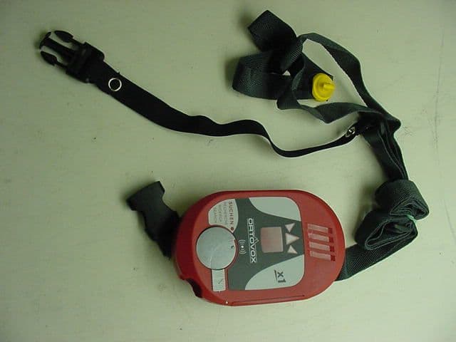
KF5ORTOVOXX1
Jul 25, 2002Avalanche Transceiver
Equipment Class
DCD - Part 15 Low Power Transmitter Below 1705 kHz