KH7-MRLN-A128Bluetooth Protocol Analyzer
Computer Access Technology Corporation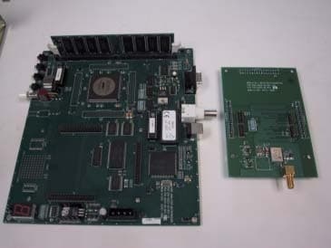
Click to zoom
Application Details
- Equipment Class
- DSS - Part 15 Spread Spectrum Transmitter
- Date of Grant
- Nov 12, 2001
- Application Purpose
- Original Equipment
- Date of Application
- Sep 19, 2001
- Equipment Note
- Bluetooth Protocol Analyzer
- Frequency Range
- 2402.00000000 - 2480.00000000
- Country
- United States
Documents & Files
Document Text
Text extracted from the exhibit documents filed with the FCC. Open a document above to read the original.
Users Manual
2403 Walsh Avenue, Santa Clara, CA 95051-1302 Tel: +1/408.727.6600 Fax: +1/408.727.6622 Version 1.6 8 June, 2001 CATC Merlin ™ Bluetooth ™ Protocol Analyzer User’s Manual ii Merlin Protocol Analyzer User’s ManualCATCVersion 1.6 Document Disclaimer The information contained in this document has been carefully checked and is believed to be reliable. However, no responsibility can be assumed for inaccuracies that may not have been detected. CATC reserves the right to revise the information presented in this document without notice or penalty. Trademarks and Servicemarks CATC, Merlin, NetMate, Advisor, Chief, FireInspector, Inspector, Detective, Traffic Generator, BusEngine, USB4DOS, UPT, HPT, UHT, Galaxy, and Andromeda are trademarks of Computer Access Technology Corporation. Microsoft, Windows, and Windows NT are registered trademarks of Microsoft Inc. All other trademarks are property of their respective companies. Copyright Copyright © 2001, Computer Access Technology Corporation (CATC); All Rights Reserved. This document may be printed and reproduced without additional permission, but all copies should contain this copyright notice. Part number: 730-0017-00 iii Merlin Protocol Analyzer User’s ManualCATCVersion 1.6 TABLE OF CONTENTS Chapter 1 Overview. . . . . . . . . . . . . . . . . . . . . . . . . . . . . . . . . . . . . 1 Bluetooth™ Overview . . . . . . . . . . . . . . . . . . . . . . . . . . . . . . . 1 General Description . . . . . . . . . . . . . . . . . . . . . . . . . . . . . . . . . 2 Features . . . . . . . . . . . . . . . . . . . . . . . . . . . . . . . . . . . . . . . . . . . 4 General . . . . . . . . . . . . . . . . . . . . . . . . . . . . . . . . . . . . . . . . 4 Physical Components . . . . . . . . . . . . . . . . . . . . . . . . . . . . . 4 Display Options . . . . . . . . . . . . . . . . . . . . . . . . . . . . . . . . . 5 Recording Options . . . . . . . . . . . . . . . . . . . . . . . . . . . . . . . 5 Traffic Generation . . . . . . . . . . . . . . . . . . . . . . . . . . . . . . . . 5 Bluetooth™ BusEngine . . . . . . . . . . . . . . . . . . . . . . . . . . . 5 Specifications . . . . . . . . . . . . . . . . . . . . . . . . . . . . . . . . . . . . . . 6 Package . . . . . . . . . . . . . . . . . . . . . . . . . . . . . . . . . . . . . . . . 6 Power Requirements . . . . . . . . . . . . . . . . . . . . . . . . . . . . . . 6 Environmental Conditions . . . . . . . . . . . . . . . . . . . . . . . . . 6 Switches . . . . . . . . . . . . . . . . . . . . . . . . . . . . . . . . . . . . . . . 6 LEDs . . . . . . . . . . . . . . . . . . . . . . . . . . . . . . . . . . . . . . . . . 6 Recording Memory Size . . . . . . . . . . . . . . . . . . . . . . . . . . . 6 Certification . . . . . . . . . . . . . . . . . . . . . . . . . . . . . . . . . . . . 6 Chapter 2 Quick Installation . . . . . . . . . . . . . . . . . . . . . . . . . . . . . 7 Setting Up the Analyzer . . . . . . . . . . . . . . . . . . . . . . . . . . . . . . 7 Installing the Software . . . . . . . . . . . . . . . . . . . . . . . . . . . . . . . 7 Your First Bluetooth™ Recording . . . . . . . . . . . . . . . . . . . . . . 8 Chapter 3 Detailed Installation . . . . . . . . . . . . . . . . . . . . . . . . . . 11 System Components/Packing List . . . . . . . . . . . . . . . . . . . . . 11 The Installed Merlin Unit . . . . . . . . . . . . . . . . . . . . . . . . . . . . 11 Merlin System Setup. . . . . . . . . . . . . . . . . . . . . . . . . . . . . . . . 12 AC Power Source . . . . . . . . . . . . . . . . . . . . . . . . . . . . . . . . . . 12 External Interface Breakout Board . . . . . . . . . . . . . . . . . . . . . 13 Breakout Board External Output Signalling Pins . . . . . . . 14 Prototype Rework Area . . . . . . . . . . . . . . . . . . . . . . . . . . 15 PC Connection . . . . . . . . . . . . . . . . . . . . . . . . . . . . . . . . . . . . 15 Antenna Information . . . . . . . . . . . . . . . . . . . . . . . . . . . . . . . . 15 Analyzer PC Requirements. . . . . . . . . . . . . . . . . . . . . . . . . . . 15 Merlin Program Installation . . . . . . . . . . . . . . . . . . . . . . . . . . 16 Loading the Merlin USB Drivers . . . . . . . . . . . . . . . . . . . 16 Installing the Merlin Application Program . . . . . . . . . . . . 16 Merlin Program Startup . . . . . . . . . . . . . . . . . . . . . . . . . . . . . 17 Making a Recording . . . . . . . . . . . . . . . . . . . . . . . . . . . . . . . . 18 Chapter 4 Upgrades. . . . . . . . . . . . . . . . . . . . . . . . . . . . . . . . . . . . 19 iv Merlin Protocol Analyzer User’s ManualCATCVersion 1.6 Software, Firmware, and BusEngine Revisions . . . . . . . . . . . 19 Software Upgrades . . . . . . . . . . . . . . . . . . . . . . . . . . . . . . . . . 20 BusEngine and Firmware Upgrades . . . . . . . . . . . . . . . . . . . . 20 Automatic Upgrades . . . . . . . . . . . . . . . . . . . . . . . . . . . . . 20 Manual Upgrades to BusEngine and Firmware . . . . . . . . 22 Upgrading the BusEngine . . . . . . . . . . . . . . . . . . . . . . . . . 22 Upgrading the Firmware . . . . . . . . . . . . . . . . . . . . . . . . . . 24 Chapter 5 Software Overview . . . . . . . . . . . . . . . . . . . . . . . . . . . 25 The Main Display Windows . . . . . . . . . . . . . . . . . . . . . . . . . . 25 View Options . . . . . . . . . . . . . . . . . . . . . . . . . . . . . . . . . . . . . 27 Tool Bar . . . . . . . . . . . . . . . . . . . . . . . . . . . . . . . . . . . . . . 27 Status Bar . . . . . . . . . . . . . . . . . . . . . . . . . . . . . . . . . . . . . . . . 29 Recording Progress . . . . . . . . . . . . . . . . . . . . . . . . . . . . . . 29 Recording Status . . . . . . . . . . . . . . . . . . . . . . . . . . . . . . . . 30 Analyzer Status . . . . . . . . . . . . . . . . . . . . . . . . . . . . . . . . . 30 Search Status . . . . . . . . . . . . . . . . . . . . . . . . . . . . . . . . . . . 31 Zoom In. . . . . . . . . . . . . . . . . . . . . . . . . . . . . . . . . . . . . . . 31 Zoom Out . . . . . . . . . .…
Text truncated - open the document above for the full version.
Users Manual
45 Merlin Protocol Analyzer User’s ManualCATCVersion 1.6 The wizard will close and your trace will display. 6.2 Recording an Existing Piconet Using Recording Wizard to record an existing piconet is similar to recording a new piconet. The main difference is that you will be asked if your Master device can support multiple slave devices and whether it can respond to pages once it has created a piconet with another device. Step 1To start the Recording Wizard, press or select Setup > Recording Wizard from the menu. The Recording Wizard introductory page will open: 46 Merlin Protocol Analyzer User’s ManualCATCVersion 1.6 Step 2Press Next to advance to the next screen. You will see three choices: Step 3Select the second option: I want Merlin to record traffic on a piconet that has already been established. Step 4Press Next. You will see four choices: Select the hop mode appropriate to your area. Step 5Select the hop mode appropriate to your area, then press Next. 47 Merlin Protocol Analyzer User’s ManualCATCVersion 1.6 You will see two choices: Step 6Select Perform Inquiry Now. You will see two choices: Step 7Select the first option: I want Merlin to search for all Bluetooth devices within range. If you want to limit the inquiry to a class of devices, select the second option and enter the hexadecimal value for the device class in the text box. 48 Merlin Protocol Analyzer User’s ManualCATCVersion 1.6 Step 8Press Next. You will see two choices: Step 9If you want to change the search duration, type in a new value into the text box. Otherwise, use the default value (20 seconds), then press Next. The PC-Merlin hardware connection will be tested. If Merlin cannot be detected, the following message will display: 49 Merlin Protocol Analyzer User’s ManualCATCVersion 1.6 If Merlin passes the hardware test, it will then goes onto conduct a General Inquiry to locate local Bluetooth devices. If Merlin finds Bluetooth devices, it will display the following message: Step 10To display a list of the discovered devices, press the button 50 Merlin Protocol Analyzer User’s ManualCATCVersion 1.6 marked Show Devices Found. A screen will display showing the devices that Merlin discovered through the General Inquiry: If you feel that the list is incomplete, you can close this window and press the button marked Repeat. This will cause Merlin to repeat the General Inquiry and recollect information on local Bluetooth devices. Step 11Press OK to close the Bluetooth Neighborhood window. Step 12Press Next to advance to the next screen. The following screen will prompt you for the Master device’s address. The address can be selected from the drop-down menu or typed into the box: Step 13Select or type in the Master device’s address into the box 51 Merlin Protocol Analyzer User’s ManualCATCVersion 1.6 next to the label Piconet Master Address. Step 14Press Next. The following screen will display. This screen asks you which of the following two options apply to your Master device. For some devices, both options will apply. You can select either or both options. They are not mutually exclusive: If the Master supports inquiries while in a connected state, select the first option. This will set Merlin to use the 'Sync & Record' mode in its attempts to synchronize to the Master. This will also cause the wizard to skip to step 8. If the Master can support piconets with multiple slaves, select the second option. If you select this box alone (i.e., you leave the first box unchecked), Merlin will use the 'Passive Sync & Record' mode to synchronize to the Master. The wizard will then advance to Screen 8*. If the first checkbox was selected, Merlin will use 'Sync & Record' no matter what was set in the second box. Step 15Select the options that pertain to your device, then press Next. 52 Merlin Protocol Analyzer User’s ManualCATCVersion 1.6 The screen that follows will depend on the options you selected above. If you selected the first option (=’Sync & Record’), the following screen will display. This screen gives you the option of verifying the presence of the Master device just before synchronizing. Step 16If you want to skip the Master verification, put a check in the box. If you are in doubt, leave the box unchecked. If you selected only the second option in Step 15 (=’Passive Sync & Record’), the following screen will display. This screen asks you for the address of the Page Target device -- which in this case is Merlin. Since the devices in your piconet are not able to respond to inquiries, Merlin will not be able to page the devices and join the piconet. Instead, you will assign Merlin an address here in this 53 Merlin Protocol Analyzer User’s ManualCATCVersion 1.6 screen, then direct your piconet Master device to connect to Merlin. The Master will attempt to connect to Merlin and therein give Merlin the information it needs to record the Master and slave devices. Step 17Type in an address of your choosing for Merlin (= Page Target). You are making up an address for Merlin that the Master will use to try to connect to Merlin. Step 18Press Next Merlin will then display your current settings. The Advanced button will open the Recording Options dialog box shown on page 42 and described in detail in Chapter 7. Step 19Press Next to begin the recording. If the Merlin hardware is not ready or connected or is in the process of booting up, the following information message box will display: Step 20If the above information box opened, press OK to close it. 54 Merlin Protocol Analyzer User’s ManualCATCVersion 1.6 The following dialog box will display: Step 21Press Retry or Back to re-attempt the process. If the hardware failure described in Steps 20 and 21 do not occur, Merlin will conduct an inquiry. The screen will show that Merlin is going to attempt a recording in either ’Passive Sync & Record’ mode as shown below or in ’Sync & Record’ mode depending on the options you selected in Step 15. Step 22If you are recording in ’Passive Sync & …
Text truncated - open the document above for the full version.
Cover Letter(s)
UNIVERSAL COMPLIANCE LABORATORIES 775B Mabury Road, San Jose, CA 95133 PH:408-453-8744 FX: 408-453-8747 www. universalcompliance.com 7/31/01 American TCB 6731 Whittier Avenue Ste C110 McLean, VA 22101 Attn: William Graff Applicant:Computer Access Technology Corporation Equipment: “Merlin “ Bluetooth Protocol Analyzer FCC ID:KH7-MRLN-A128 FCC Rules:2, 15.247, Confidentiality On behalf of the Applicant, enclosed please find Application Form 731, engineering Test Report, and all pertinent documentation for the approval of the referenced equipment as shown. Filing Fees are being forwarded to your office ASAP. Should you require any further information, please don’t hesitate to contact Bob Cole ([email protected]), who is authorized to act as agent. Best Regards Bob Cole President UCL
Cover Letter(s)
Declaration of Identity FOR RADIO EQUIPMENT We, the undersigned,Ericsson Microelectronics Isafjordsgatan 16, Kista SE-164 8 1 Stockholm SWEDEN certify that the following equipment: Bluetooth module ROANA 20 1 132, Bluetooth module ROK 10 1007 Bluetooth module ROK 10 1008 Bluetooth module FCCID:CGK8001001 are identical with the same Radio interface. The product number ROANA is not used anymore but the ROK numbers will be used. ROK 10 1 008 carry a Point-to-Point Baseband ROK 101 007 carry a Point-to-Multi Baseband Only a name change has taken place, equipment identified with all numbers have identical Radio interface. Drawn up in Stockholm on April 03,200l . ..CrT.tif . Cony Curio Product manager
Cover Letter(s)
Enabling Global Connectivity Computer Access Technology Corporation 2403 Walsh Avenue, Santa Clara, CA 95051-1302 Tel: (408) 727-6600, Fax: (408) 727-6622 www.catc.com LETTER OF AUTHORIZATION August 13, 2001 American Telecommunications Certification Body, Inc. 6731 Whittier Avenue Suite C II 0 McLean, VA 22101 Gentlemen: 1, Please be advised that COMPUTER ACCESS TECHNOLOGY authorizes Universal Compliance Labs to act on our behalf, until otherwise notified, for applications submitted to American Teleconununications Certification Body, Inc. (ATCB). We certify that we are not subject to denial of federal benefits, that includes FCC benefits, pursuant to Section 5301 of the Anti-Drug Abuse ACT of 1988, U.S.C. 862. Further, no party, as defined in 47 CFR 1.2002(b), to the application is subject to denial of federal benefits, that includes FCC benefits. Thank you for your attention to this matter. 19 Albert F. Lee Vice President Operations
Cover Letter(s)
Computer Access Technology Corp. (CATC) Response To FCC Fax.doc Last saved on 11/5/2001 9:09 PM Page 1 of 2 Gentlemen: This letter addresses the issues raised in your fax dated October 11, 2001 regarding FCC ID: KH7-MRLN-A128 Issue 1: A new exhibit “RequestForConfidentiality.pdf“ has been added Issues 2 and 3: Exhibits "Declaration of Identity", "Block diagram for Ericsson Bluetooth modules ROK 101 007 and ROK 101 008", "Processing Gain Test Setup" and "PROCESSING GAIN MEASUREMENT" are Ericsson documents provided in support of the following claim regarding the processing gain measurements for Merlin: CATC's Merlin uses the same radio chip (PBA 313 01/2) as is used by Ericsson in their own Bluetooth module (FCC IDs CGK8001001 and PNI8001001; see BlockDiagram.pdf). The radio chip implements the Gaussian Frequency Shift Keying modulation (GFSK; BT product of 0.5) required by the Bluetooth specification. There is no control over the modulation by the baseband controller therefore the processing gain for Merlin is the same as the one documented by Ericsson for their module (see “Report on processing gain results.pdf“ and CoverLetter3.pdf). Neither one of the ROK modules is actually installed in the Merlin device (but as stated above Merlin is using the same radio chip). Photos of the modules should therefore not be needed. Issue 4 and 5: With an RF output power of under 3 mW and an antenna gain of less than 3dBi, we will categorize this device as safe to Transmitter Category V(bii) per the TCB Exposure Procedures of 11/15/2000. A new exhibit "RF Safety User Information.pdf" shows the modified RF safety instructions section of the Merlin manual. The radio chip used in Merlin has (as specified by the Ericsson) a very wide possible range of output power. +4.5 dBm or about 2.8 mW is the maximal value and was therefore used by CATC in the RF Exposure document to cover the worst case scenario. Actual measurements showed much lower values (102.8 dBuV or about -4 dBm). A new exhibit “RF Hazard Distance Calculation.pdf“ has been added which shows calculations for both values. Issue 6: The hopping sequence for any given Bluetooth device that is not part of a piconet depends on its Bluetooth clock and its unique Bluetooth address. As described in section 10.3 of the Bluetooth specification (see exhibit TransmitterSync.pdf) every device has its own free running clock. The fact that both clock and address are unique to a device guarantee that the hopping sequences of two devices will not be synchronized (see exhibit Hopping2.pdf on how the sequence is generated) Devices (up to 8) that form a piconet on the other hand are synchronized to the piconet master and they use a Time-Division Duplex (TDD) scheme to guarantee that there are never two devices transmitting at the same time (see exhibits Hopping1.pdf, section 2.2 and MasterControl.pdf, section 10.8.5.1) Computer Access Technology Corp. (CATC) Response To FCC Fax.doc Last saved on 11/5/2001 9:09 PM Page 2 of 2 Issue 7: The pseudorandom hopping sequence depends on the Bluetooth clock of the piconet master and part of its Bluetooth address. The details of the sequence computation are described in section 11 of the Bluetooth specification (see exhibit Hopping2.pdf) New exhibits HoppingSample1.pdf, HoppingSample2.pdf and HoppingSample3.pdf have been added. Each document shows a sample hopping sequence (covering 1 second) for a different Bluetooth Device Address. Issue 8: This issue is addressed by section 2.2 of the Bluetooth specification. Every transmission starts on a new frequency (defined by the hopping sequence as described above). If a transmission covers several (up to 5) frequency hops, the frequency remains fixed for the whole packet. The hop frequency in the first slot after a multi-slot packet uses the frequency as determined by the current Bluetooth clock value (see exhibit Hopping1.pdf for more details) Issue 9: Synchronization of transmitter and receiver is performed during the setup of a piconet (see exhibit TransmitterSync.pdf, section 10.3). Once a piconet is established all the slave devices follow the same hopping sequence based on the clock and address of the piconet master. The master always has full control over the piconet (see exhibit MasterControl.pdf, section 10.8.5.1). Slave devices stay synchronized to the master by regularly (i.e. every time they receive a packet from the master) updating their clock offsets. Issue 10: A new exhibit "CATC Merlin Power Density Document.pdf" has been added
Cover Letter(s)
Declaration of Identity FOR RADIO EQUIPMENT We, the undersigned,Ericsson Microelectronics Isafjordsgatan 16, Kista SE-164 8 1 Stockholm SWEDEN certify that the following equipment: Bluetooth module ROANA 20 1 132, Bluetooth module ROK 10 1007 Bluetooth module ROK 10 1008 Bluetooth module FCCID:CGK8001001 are identical with the same Radio interface. The product number ROANA is not used anymore but the ROK numbers will be used. ROK 10 1 008 carry a Point-to-Point Baseband ROK 101 007 carry a Point-to-Multi Baseband Only a name change has taken place, equipment identified with all numbers have identical Radio interface. Drawn up in Stockholm on April 03,200l . ..CrT.tif . Cony Curio Product manager
Cover Letter(s)
Computer Access Technology Corp. (CATC) Response To FCC Email.doc Last saved on 11/12/2001 10:10 AM Page 1 of 1 Gentlemen: This letter addresses the issues raised in your email dated November 9, 2001 regarding the following FCC ID: KH7-MRLN-A128 Issue 1: The measured output of the device at the antenna connector is indeed -4 dBm, therefore the EIRP including antenna gain (2 dBi) is -2 dBm Issue 2: The radio chip used in Merlin contains both the RF and IF (3 MHz) filter circuits. Its input is the signal from the antenna and its output is the extracted digital bit stream (1 MHz bit rate). A block diagram and description of the chip can be found on page 11 of the exhibit "PBA 313 01/2 Bluetooth Radio". This radio chip is the same as used in the ROK module of which we submitted the processing gain measurements.
External Photos
CATC Merlin / UCL Report # 7/21/01 EXTERNAL PHOTOS CATC Merlin – Rear View CATC Merlin Front View Page 1 of 2 CATC Merlin / UCL Report # 7/21/01 EXTERNAL PHOTOS Antenna / Connector Page 2 of 2
ID Label/Location Info
MERLIN FCC IDENTIFICATION AND COMPLIANCE LABEL MERLIN FCC ID: KH7B-MRLN-A128 This device complies with Part 15 of the FCC Rules. Operation is subject to the following two conditions: (1) this device may not cause harmful interference, and (2) this device must accept any interference received, including interference that may cause undesired operation.
Internal Photos
CATC Merlin / UCL Report # 7/21/01 INTERNAL PHOTOS Chassis Cover Removed Radio Module PCB – Bottom View / Main PCB – Top View Page 1 of 2 CATC Merlin / UCL Report # 7/21/01 INTERNAL PHOTOS Main PCB / Radio PCB – Top View Power Supply PCB – Bottom View Page 2 of 2
Internal Photos
CATC Merlin / UCL Report # 7/21/01 INTERNAL PHOTOS Power Supply PCB – Top View Page 1 of 2 CATC Merlin / UCL Report # 7/21/01 INTERNAL PHOTOS Internal Construction Page 2 of 2
Internal Photos
CATC Merlin / UCL Report #7/21/01 INTERNAL PHOTOS Page 1 of 2 Chassis Cover Removed Radio Module PCB – Bottom View / Main PCB – Top View CATC Merlin / UCL Report #7/21/01 INTERNAL PHOTOS Page 2 of 2 Main PCB / Radio PCB – Top View Power Supply PCB – Bottom View
Internal Photos
CATC Merlin / UCL Report #7/21/01 INTERNAL PHOTOS Page 1 of 2 Power Supply PCB – Top View CATC Merlin / UCL Report #7/21/01 INTERNAL PHOTOS Page 2 of 2 Internal Construction
Internal Photos
CATC Merlin Main Board CATC Merlin Main Board – Solder Side CATC Merlin Power Supply
Operational Description
Physical Channel22 February 200143 BLUETOOTH SPECIFICATION Version 1.1page 43 of 1084 Baseband Specification 2 PHYSICAL CHANNEL 2.1 CHANNEL DEFINITION The channel is represented by a pseudo-random hopping sequence hopping through the 79 or 23 RF channels. The hopping sequence is unique for the piconet and is determined by the Bluetooth device address of the master; the phase in the hopping sequence is determined by the Bluetooth clock of the master. The channel is divided into time slots where each slot corresponds to an RF hop frequency. Consecutive hops correspond to different RF hop fre- quencies. The nominal hop rate is 1600 hops/s. All Bluetooth units participating in the piconet are time- and hop-synchronized to the channel. 2.2 TIME SLOTS The channel is divided into time slots, each 625 μs in length. The time slots are numbered according to the Bluetooth clock of the piconet master. The slot numbering ranges from 0 to 2 27 -1 and is cyclic with a cycle length of 2 27 . In the time slots, master and slave can transmit packets. A TDD scheme is used where master and slave alternatively transmit, see Figure 2.1 on page 44. The master shall start its transmission in even- numbered time slots only, and the slave shall start its transmission in odd- numbered time slots only. The packet start shall be aligned with the slot start. Packets transmitted by the master or the slave may extend over up to five time slots. The RF hop frequency shall remain fixed for the duration of the packet. For a single packet, the RF hop frequency to be used is derived from the current Bluetooth clock value. For a multi-slot packet, the RF hop frequency to be used for the entire packet is derived from the Bluetooth clock value in the first slot of the packet. The RF hop frequency in the first slot after a multi-slot packet shall use the frequency as determined by the current Bluetooth clock value. Figure 2.2 on page 44 illustrates the hop definition on single- and multi-slot packets. If a packet occupies more than one time slot, the hop frequency applied shall be the hop frequency as applied in the time slot where the packet transmission was started. 4422 February 2001Physical Channel BLUETOOTH SPECIFICATION Version 1.1page 44 of 1084 Baseband Specification Figure 2.1: TDD and timing Figure 2.2: Multi-slot packets f(k)f(k+1)f(k+2) 625 μs Master Slave f(k) 625 μs f(k+1)f(k+2)f(k+3)f(k+4)f(k+5) f(k)f(k+3)f(k+4)f(k+5) f(k)f(k+5) f(k+6) f(k+6) f(k+6)
Operational Description
12622 February 2001Hop Selection BLUETOOTH SPECIFICATION Version 1.1page 126 of 1084 Baseband Specification 11 HOP SELECTION In total, 10 types of hopping sequences are defined − five for the 79-hop and five for the 23-hop system, respectively. Using the notation of parentheses () for figures related to the 23-hop system, these sequences are: •A page hopping sequence with 32 (16) unique wake-up frequencies dis- tributed equally over the 79 (23) MHz, with a period length of 32 (16); •A page response sequence covering 32 (16) unique response frequencies that all are in an one-to-one correspondence to the current page hopping sequence. The master and slave use different rules to obtain the same sequence; •An inquiry sequence with 32 (16) unique wake-up frequencies distributed equally over the 79 (23) MHz, with a period length of 32 (16); •A inquiry response sequence covering 32 (16) unique response frequen- cies that all are in an one-to-one correspondence to the current inquiry hop- ping sequence. •A channel hopping sequence which has a very long period length, which does not show repetitive patterns over a short time interval, but which dis- tributes the hop frequencies equally over the 79 (23) MHz during a short time interval; For the page hopping sequence, it is important that we can easily shift the phase forward or backward, so we need a 1-1 mapping from a counter to the hop frequencies. For each case, both a hop sequence from master to slave and from slave to master are required. The inquiry and inquiry response sequences always utilizes the GIAC LAP as lower address part and the DCI (Section 5.4 on page 72) as upper address part in deriving the hopping sequence, even if it concerns a DIAC inquiry. 11.1 GENERAL SELECTION SCHEME The selection scheme consists of two parts: •selecting a sequence; •mapping this sequence on the hop frequencies; The general block diagram of the hop selection scheme is shown in Figure 11.1 on page 127. The mapping from the input to a particular hop frequency is per- formed in the selection box. Basically, the input is the native clock and the cur- rent address. In CONNECTION state, the native clock (CLKN) is modified by an offset to equal the master clock (CLK). Only the 27 MSBs of the clock are used. In the page and inquiry substates, all 28 bits of the clock are used. How- ever, in page substate the native clock will be modified to the master’s estimate of the paged unit. Hop Selection22 February 2001127 BLUETOOTH SPECIFICATION Version 1.1page 127 of 1084 Baseband Specification The address input consists of 28 bits, i.e., the entire LAP and the 4 LSBs of the UAP. In CONNECTION state, the address of the master is used. In page sub- state the address of the paged unit is used. When in inquiry substate, the UAP/LAP corresponding to the GIAC is used. The output constitutes a pseudo- random sequence, either covering 79 hop or 23 hops, depending on the state. Figure 11.1: General block diagram of hop selection scheme. For the 79-hop system, the selection scheme chooses a segment of 32 hop frequencies spanning about 64 MHz and visits these hops once in a random order. Next, a different 32-hop segment is chosen, etc. In case of the page, page scan, or page response substates, the same 32-hop segment is used all the time (the segment is selected by the address; different units will have dif- ferent paging segments). In connection state, the output constitutes a pseudo- random sequence that slides through the 79 hops or 23 hops, depending on the selected hop system. For the 23-hop systems, the segment size is 16. The principle is depicted in Figure 11.2 . Figure 11.2: Hop selection scheme in CONNECTION state. SELECTION BOX hop frequency UAP/LAP 23/79 mode CLOCK 27 28 04662642 781 737577 segment 1 segment 2 segment 3 ∆ Europe/US Japan/France/Spain 79 23 32 16 16 8 segment length# of hops ∆ 12822 February 2001Hop Selection BLUETOOTH SPECIFICATION Version 1.1page 128 of 1084 Baseband Specification 11.2 SELECTION KERNEL The hop selection kernels for the 79 hop system and the 23 hop system are shown in Figure 11.3 on page 128 and Figure 11.4 on page 128, respectively. The X input determines the phase in the 32-hop segment, whereas Y1 and Y2 selects between master-to-slave and slave-to-master transmission. The inputs A to D determine the ordering within the segment, the inputs E and F determine the mapping onto the hop frequencies. The kernel addresses a register containing the hop frequencies. This list should be created such that first all even hop fre- quencies are listed and then all odd hop frequencies. In this way, a 32-hop seg- ment spans about 64 MHz, whereas a 16-hop segment spans the entire 23-MHz. Figure 11.3: Block diagram of hop selection kernel for the 79-hop system. Figure 11.4: Block diagram of hop selection kernel for the 23-hop system. X O R XOR 55 XADD mod32 AB 4 55 5 ADD EF 7 7 7 0 2 4 CD 5 9 5 Y1 Y2 mod 79 1 78 3 77 PERM5 X O R XOR ADD AB 45 ADD EF 77 0 2 4 CD 5 9 5 Y1 Y2 X 4 mod16 mod 23 22 1 3 21 4445 PERM4 Hop Selection22 February 2001129 BLUETOOTH SPECIFICATION Version 1.1page 129 of 1084 Baseband Specification The selection procedure consists of an addition, an XOR operation, a permuta- tion operation, an addition, and finally a register selection. In the remainder of this chapter, the notation A i is used for bit i of the BD_ADDR. 11.2.1 First addition operation The first addition operation only adds a constant to the phase and applies a modulo 32 or a modulo 16 operation. For the …
Text truncated - open the document above for the full version.
Contact Information
Applicant
Ken Kimura(Manufacturing Engineering Manager)
Technical Contact
Universal Compliance LabsBob Cole
[email protected]408 453 8744
775B Mabury Rd · San Jose, California · United States
Test Firm
Universal Compliance LabsBob Cole
Technical Specifications
| # | Rule Parts | Frequency Range | Power Output |
|---|---|---|---|
| 1 | 15C | 2.40 GHz - 2.48 GHz | 400.00 µW |
Other Applications from Computer Access Technology Corporation
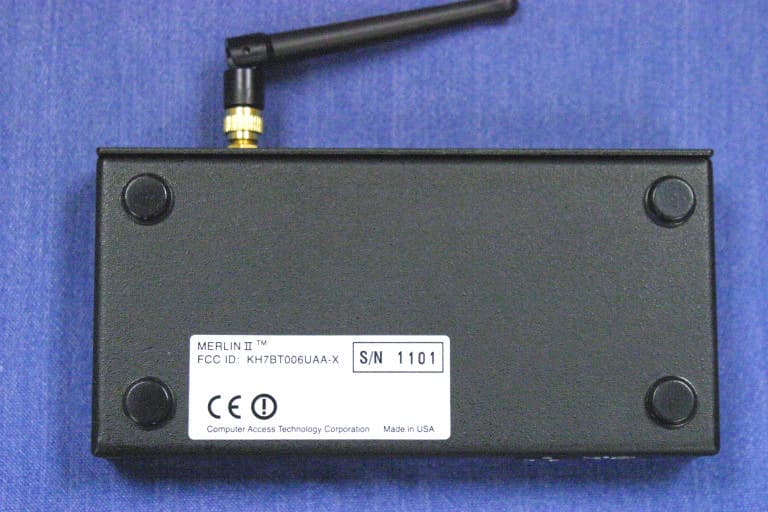
KH7BT006UAA-X
Jan 04, 2004Bluetooth Protocol Analyzer
Equipment Class
DSS - Part 15 Spread Spectrum Transmitter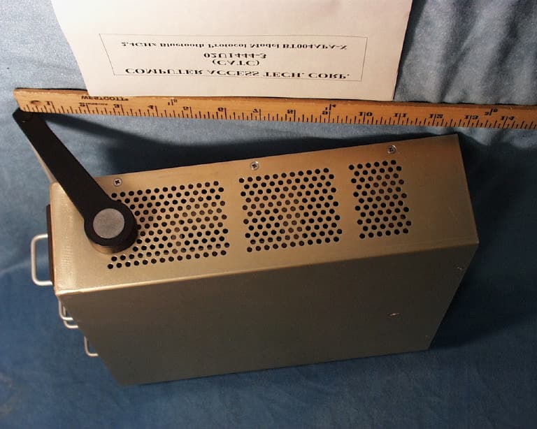
KH7BT004APA-X
Sep 23, 2002Bluetooth Protocal Analyzer and Test Generator
Equipment Class
DSS - Part 15 Spread Spectrum Transmitter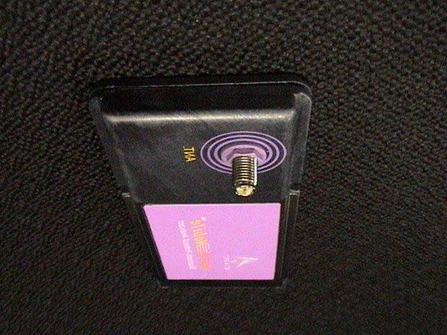
KH7BT005UAA-X
Aug 13, 2002Bluetooth Portable Protocol Analyzer
Equipment Class
DSS - Part 15 Spread Spectrum TransmitterKH7AB0001
Jun 04, 1995Serial Bus Interface Card
Equipment Class
JBP - Part 15 Class B Computing Device PeripheralKH7P2AB-10
Aug 30, 1994External Access Bus Interface Device
Equipment Class
JBP - Part 15 Class B Computing Device Peripheral