KH7BT004APA-XBluetooth Protocal Analyzer and Test Generator
Computer Access Technology Corporation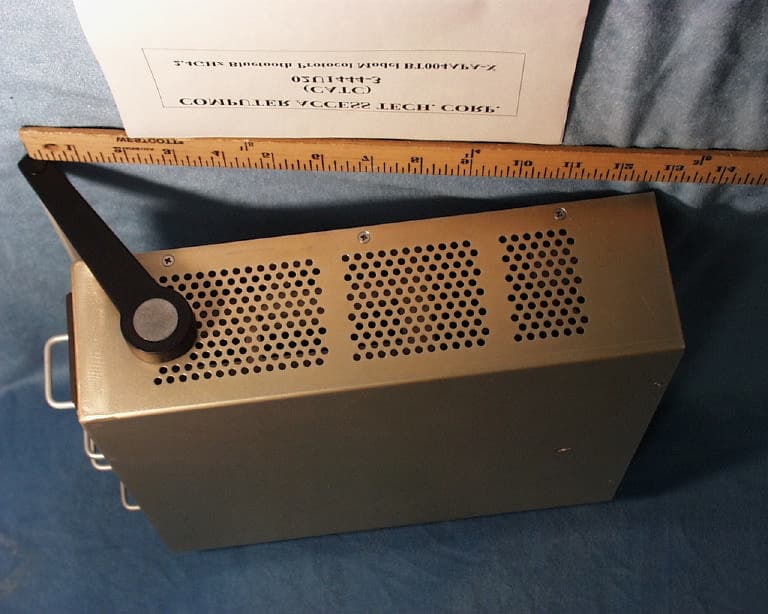
Click to zoom
Application Details
- Equipment Class
- DSS - Part 15 Spread Spectrum Transmitter
- Date of Grant
- Sep 23, 2002
- Application Purpose
- Original Equipment
- Date of Application
- Sep 23, 2002
- Equipment Note
- Bluetooth Protocal Analyzer and Test Generator
- Frequency Range
- 2402.00000000 - 2480.00000000
- Country
- United States
Documents & Files
Document Text
Text extracted from the exhibit documents filed with the FCC. Open a document above to read the original.
Users Manual
2403 Walsh Avenue, Santa Clara, CA 95051-1302 Tel: +1/408.727.6600 Fax: +1/408.727.6622 For Software Version 1.0 Manual Version 1.0 8 February, 2002 CATC BTTracer ™ Bluetooth ™ Protocol Analyzer User’s Manual 2 Merlin Protocol Analyzer User’s ManualCATCVersion 1.0 Document Disclaimer The information contained in this document has been carefully checked and is believed to be reliable. However, no responsibility can be assumed for inaccuracies that may not have been detected. CATC reserves the right to revise the information presented in this document without notice or penalty. Trademarks and Servicemarks CATC, Merlin, Merlin’s Wand, NetMate, Advisor, Chief, FireInspector, Inspector, Detective, Traffic Generator, BusEngine, USB4DOS, UPT, HPT, UHT, Galaxy, IBTracer,SATracer,andAndromedaare trademarks of Computer Access Technology Corporation. Microsoft, Windows,andWindows NTare registered trademarks of Microsoft Inc. All other trademarks are property of their respective companies. Copyright Copyright © 2002, Computer Access Technology Corporation (CATC); All Rights Reserved. This document may be printed and reproduced without additional permission, but all copies should contain this copyright notice. FCC Conference Statement This equipment has been tested and found to comply with the limits for a Class A digital device and an intentional radiator, pursuant to Part 15 of the FCC Rules. These limits are designed to provide reasonable protection against harmful interference when the equipment is operated in a commercial environment. This equipment generates, uses, and can radiate radio frequency energy and, if not installed and used in accordance with the instruction manual, may cause harmful interference to radio communications. Operation of this equipment in a residential area is likely to cause harmful interference in which case the user will be required to correct the interference at their own expense. The end user of this product should be aware that any changes or modifications made to this equipment without the approval of CATC could result in the product not meeting the Class A limits, in which case the FCC could void the user's authority to operate the equipment. 3 Merlin Protocol Analyzer User’s ManualCATCVersion 1.0 Important Notice: To comply with FCC RF exposure requirements (sections 1.1307 and 1.310 of the Rules) only the antenna supplied by CATC must be used for this device. The antenna must be located at least 20 cm away from all persons. EU Conference Statement This equipment complies with the R&TT Directive 1999/5/EC. It has been tested and found to comply with EN55022:1994/A1:1995/A2:1997 Class A, EN61000-4-2:1995, EN61000-4-3:1995, EN61000-4-4:1995, EN61000-4-5:1995, EN61000-4-6:1995, EN61000-4-11:1994, EN61010-1:1993, and ESTI EN 300 328-1 V1.2.2 (2000-07). Manual Version 1.8Part number: 730-0017-00 4 Merlin Protocol Analyzer User’s ManualCATCVersion 1.0 iii BTTracerProtocol Analyzer User’s ManualCATCVersion 1.0 TABLE OFCONTENTS Chapter1 Overview.....................................1 Bluetooth™Overview..............................................1 GeneralDescription ...............................................2 Automation.......................................................4 Features .........................................................4 General ...................................................4 Physical Components........................................5 DisplayOptions ............................................5 RecordingOptions ..........................................5 TrafficGeneration ..........................................5 Bluetooth™BusEngine ......................................6 Specifications.....................................................7 Package...................................................7 PowerRequirements.........................................7 Environmental Conditions ....................................7 Switches ..................................................7 LEDs ....................................................7 RecordingMemorySize .....................................7 Certification ...............................................7 Chapter2 QuickInstallation .............................9 SettingUptheAnalyzer.............................................9 InstallingtheSoftware..............................................9 YourFirstBluetooth™Recording....................................10 Chapter3 DetailedInstallation...........................13 System Components/Packing List . ...................................13 TheInstalledMerlinUnit...........................................13 MerlinSystemSetup ..............................................14 ACPowerSource.................................................14 ExternalInterfaceBreakoutBoard....................................15 BreakoutBoardExternalOutputSignallingPins..................16 PrototypeReworkArea......................................17 PCConnection...................................................17 AntennaInformation ..............................................17 AnalyzerPCRequirements .........................................17 MerlinProgramInstallation.........................................18 LoadingtheMerlinUSBDrivers..............................18 InstallingtheMerlinApplicationProgram ......................18 MerlinProgramStartup............................................19 MakingaRecording...............................................20 Chapter4 Updates.....................................21 Software,Firmware,andBusEngineRevisions..........................21 SoftwareUpdates.................................................22 iv BTTracerProtocol Analyzer User’s ManualCATCVersion 1.0 SoftwareLicenseUpdates ..........................................22 Viewinglicensinginformation................................23 BusEngineandFirmwareUpdateUpdates..............................23 AutomaticUpdates.........................................24 Manu…
Text truncated - open the document above for the full version.
Users Manual
2403 Walsh Avenue, Santa Clara, CA 95051-1302 Tel: +1/408.727.6600 Fax: +1/408.727.6622 Document Revision 1.22 June 18, 2002 730-0019-00 CATC Merlin’s Wand ™ 1.22 Bluetooth ™ Test Generator User’s Manual CATC MERLIN’S WAND 1.22 User’s Manual ii Part number: 730-0019-00 CATC Merlin’s Wand 1.22 Bluetooth Test Generator User’s Manual, Document Revision 1.22 Document Disclaimer The information contained in this document has been carefully checked and is believed to be reliable. However, no responsibility can be assumed for inaccuracies that may not have been detected. CATC reserves the right to revise the information presented in this document without notice or penalty. Trademarks and Servicemarks CATC, Merlin’s Wand, and Merlin are trademarks of Computer Access Technology Corporation. Bluetooth is a trademark owned by Bluetooth SIG, Inc. and is used by Computer Access Technology Corporation under license. Microsoft, Windows, and Windows NT are either registered trademarks or trademarks of Microsoft Corporation in the United States and/or other countries. RadioShack is a registered trademark of RadioShack Corporation. GN Netcom is a registered trademark of GN Netcom, Inc. Motorola is a registered trademark of Motorola, Inc. Belkin is a registered trademark of Belkin Components. Coby is a registered trademark of Coby Electronics Corporation. Plantronics is a registered trademark of Plantronics, Inc. Intel, Pentium, and Celeron are trademarks or registered trademarks of Intel Corporation or its subsidiaries in the United States and other countries. AMD, Athlon, Duron, and AMD-K6 are trademarks of Advanced Micro Devices, Inc. All other trademarks are property of their respective companies. Copyright Copyright 2002, Computer Access Technology Corporation (CATC). All rights reserved. This document may be printed and reproduced without additional permission, but all copies should contain this copyright notice. iii CATC MERLIN’S WAND 1.22 User’s Manual Merlin’s Wand Conformance Statements FCC Conformance Statement This equipment has been tested and found to comply with the limits for both a Class A and Class B digital device, pursuant to Part 15 of the FCC Rules. These limits are designed to provide reasonable protection against harmful interference when the equipment is operated in a commercial or residential environment. This equipment generates, uses, and can radiate radio frequency energy, and, if not installed and used in accordance with the instruction manual, may cause harmful interference to radio communications. The end user of this product should be aware that any changes or modifications made to this equipment without the approval of CATC could result in the product not meeting the Class A or Class B limits, in which case the FCC could void the user's authority to operate the equipment. Important Notice This equipment contains Transmitter Module FCC ID PNI8001001. To comply with FCC RF exposure requirements (sections 1.1307 and 1.310 of the Rules) only the antenna supplied by CATC must be used for this device. The antenna must be located at least 20 centimeters away from all persons. EU Conformance Statement This equipment complies with the R&TT Directive 1999/5/EC. It has been tested and found to comply with EN55022:1998 Class B (EN61000-3-2:1998, EN61000-3-3:1995), EN55024:1998 (EN61000-4-2:1995, EN61000-4-3:1995, EN61000-4-4:1995, EN61000-4-5:1995, EN61000-4-6:1995, EN61000-4-11:1994), and EN60950:1999. The transmitter module was tested and found to comply with ETS 300 328 (1997). CATC MERLIN’S WAND 1.22 User’s Manual iv v CATC MERLIN’S WAND 1.22 User’s ManualTABLE OF CONTENTS TABLE OF CONTENTS Document Disclaimer . . . . . . . . . . . . . . . . . . . . . . . . . . . . . . . . ii Trademarks and Servicemarks . . . . . . . . . . . . . . . . . . . . . . . . . ii Copyright . . . . . . . . . . . . . . . . . . . . . . . . . . . . . . . . . . . . . . . . . ii FCC Conformance Statement . . . . . . . . . . . . . . . . . . . . . . . . . iii Important Notice. . . . . . . . . . . . . . . . . . . . . . . . . . . . . . . . iii EU Conformance Statement . . . . . . . . . . . . . . . . . . . . . . . . . . iii Table of Contents . . . . . . . . . . . . . . . . . . . . . . . . . . . . . . . . . . . . . . . .v Chapter 1 Overview. . . . . . . . . . . . . . . . . . . . . . . . . . . . . . . . . . . . . 1 Applications . . . . . . . . . . . . . . . . . . . . . . . . . . . . . . . . . . . . . . . 1 Merlin’s Wand User Interface. . . . . . . . . . . . . . . . . . . . . . . . . . 2 Key Features . . . . . . . . . . . . . . . . . . . . . . . . . . . . . . . . . . . . . . . 3 Audio Connections - Important Information . . . . . . . . . . . . . . 4 Limitations . . . . . . . . . . . . . . . . . . . . . . . . . . . . . . . . . . . . . . . . 5 Specifications . . . . . . . . . . . . . . . . . . . . . . . . . . . . . . . . . . . . . . 6 Chapter 2 Getting Started. . . . . . . . . . . . . . . . . . . . . . . . . . . . . . . . 7 System Requirements . . . . . . . . . . . . . . . . . . . . . . . . . . . . . . . . 7 Setting Up Merlin’s Wand . . . . . . . . . . . . . . . . . . . . . . . . . . . . 8 Installing the Software and Starting the Program. . . . . . . . . . . 8 Install from CD-ROM. . . . . . . . . . . . . . . . . . . . . . . . . . . . . 8 Install from installation download . . . . . . . . . . . . . . . . . . . 9 Start the program. . . . . . . . . . . . . . . . . . . . . . . . . . . . . . . . . 9 Displaying the On-Screen Help . . . . . . . . . . . . . . . . . . . . . . . . 9 Application Layout . . . . . . . . . . . . . . . . . . . . . . . . . . . . . . . . . 10 Menus . . . . . . . . . . . . . . . . . . . . . . . . . . . . . . . . . . . . . . . . . . . 12 Toolbars. . . . . . . . . . . . . . . . . . . . . . . . . . . . . . . . . . . . . . . . . . 14 Merlin’s Wand Toolbar . . . . . . . . . . . . . . . . . . . . . . . . . . 14 Merlin Bluetooth Analyzer Toolbar . . . . . . . . . . . . . . . . . 15 Tool Tips . . . . . . . . . . …
Text truncated - open the document above for the full version.
Users Manual
135 CATC MERLIN’S WAND 1.22APPENDIX A User’s ManualCommand Generator Command Descriptions ClientPut This command will initiate an OBEX Put operation in the remote device for the object defined in the FileName parameter. ClientSetPath This command will initiate an OBEX SetPath operation in the remote device. Flags indicate SetPath option such as Backup. ServerDeinit This command will deinitialize the OBEX server. Command ParametersExamplesComments Filename“C:\VCard.vcf” Return Events ClientPut_Complete ClientPut_Error Command ParametersExamplesComments Path“C:\OBEX” Flags0x00Bit 0: Back up a level before applying name (equivalent to ../ on many systems) Bit 1: Don't create an directory if it not exist. Returns an error instead. Return Events OBEX_Command_Complete ClientSetPath_Error Command ParametersExamplesComments N/A Return Events ServerDeinit_Complete ServerDeinit_Error 136 CATC MERLIN’S WAND 1.22APPENDIX A User’s ManualCommand Generator Command Descriptions ServerInit This command will initialize the OBEX server. ServerSetPath Sets the path where received OBEX files are stored. Command ParametersExamplesComments N/A Return Events ServerInit_Complete ServerInit_Error Command ParametersExamplesComments Path“C:\OBEX”Use the “...” button to select a path, or type one in. Return Events ServerSetPath_Complete ServerSetPath_Event ServerSetPath_Error 137 CATC MERLIN’S WAND 1.22APPENDIX B User’s ManualCommand Generator Examples Appendix B: Command Generator Examples This chapter provides fourteen Command Generator examples. These examples consist of command sequences that are presented in order to illustrate useful scenarios. Please note that these examples do not cover all possible alternatives. • Device Discovery and Remote Name Request • Establish Baseband Connection • Baseband Disconnection • Create Audio Connection • Establish L2CAP Connection • L2CAP Channel Disconnect • SDP Profile Service Search • SDP Reset Database and Add Profile Service Record • RFCOMM Client Channel Establishment • RFCOMM Client Channel Disconnection • RFCOMM Register Server Channel and Accept Incoming Connection • Establish TCS Connection • OBEX Server Init and Accept Incoming Connection • OBEX Client Connection and Client Get & Put Each example is illustrated with a diagram that shows communications between a host and host controller. Notation used in this chapter: • Hexagon = Condition needed to start the transaction. •Solid Arrow represents a command. •Dashed Arrow represents optional command. •Host = Merlin’s Wand application •Host Controller = Merlin’s Wand device 138 CATC MERLIN’S WAND 1.22APPENDIX B User’s ManualCommand Generator Examples B.1 Device Discovery and Remote Name Request Procedure In this scenario, Merlin’s Wand performs a General Inquiry and a Remote Name Request. Ste p1Select HCI tab. Ste p2Select Inquiry from the menu. You can use the default settings for the Inquiry_Length (8 seconds) and Num_Responses (10). Ste p3Click Execute. The Event Log should display an Inquiry_Result for each found device followed by an Inquiry_Complete event. Ste p4Select Remote_Name_Request from the menu. Select the target device from the BD ADDR drop-down menu. You can use the default settings for the other drop-down menus. Ste p5Click Execute. The target device should then respond to the command with its name. 139 CATC MERLIN’S WAND 1.22APPENDIX B User’s ManualCommand Generator Examples B.2 Establish Baseband Connection Procedure In this scenario, Merlin’s Wand creates a Baseband (ACL) Connection. This procedure assumes that Device Discovery has already been performed. See “Device Discovery and Remote Name Request” on page 138. Ste p1From the HCI menu select Create_Connection. Ste p2Select the target device from the BD_ADDR drop-down menu or enter a new BD_ADDR. Ste p3Click Execute. The Event Log should display a Connection_Complete or Connection_Failed response. 140 CATC MERLIN’S WAND 1.22APPENDIX B User’s ManualCommand Generator Examples B.3 Baseband Disconnection Procedure In this scenario, Merlin’s Wand terminates a Baseband connection. These steps continue the connection you established in the preceding scenario. This procedure assumes that an ACL connection exists. See “Establish Baseband Connection” on page 139. Ste p1From the HCI menu, select Disconnect. Ste p2From the HCI_Handle drop-down menu, select a handle. Ste p3Click Execute. For each Disconnect, you should see a return event in the Event Log that indicates the outcome of the command. 141 CATC MERLIN’S WAND 1.22APPENDIX B User’s ManualCommand Generator Examples B.4 Create Audio Connection Procedure In this scenario, Merlin’s Wand creates an SCO connection. This procedure assumes that you have established an ACL connection between Merlin’s Wand and the target device. See “Establish Baseband Connection” on page 139. Ste p1 From the HCI menu, select Add_SCO_Connection from the menu. Ste p2Select the HCI_Handle for the previously established Baseband connection (for example, 0x0001) from the HCI_Handle parameter drop-down menu. Ste p3Select a packet type from the Packet Type parameter drop-down menu. Ste p4Click Execute. The Event Log should indicate that the command was executed and that the target device responded with “Add_SCO_Connection_Complete” or “Add_SCO_Connection_Error.” 142 CATC MERLIN’S WAND 1.22APPENDIX B User’s ManualCommand Generator Examples B.5 L2CAP Connection Procedure In this scenario, Merlin’s Wand establishes an L2CAP connection. This procedure assumes that an ACL connection has been established. See “Establish Baseband Connection” on page 139. Ste p1Click the L2CAP tab to display the L2CAP drop-down menu. Ste p2Select Register_PSM from the menu. Merlin’s Wand must register its PSM channel before it can form an L2CAP connection. Ste p3Select or type a PSM from the PSM menu. Ste p4Select or type the Receive MTU from the Receive MTU menu (default value can be used). Ste p5Click Execute. Ste p6Repeat this procedure for the target d…
Text truncated - open the document above for the full version.
Cover Letter(s)
Aug. 20, 2002 Federal Communications Commission Authorization and Evaluation Division 7435 Oakland Mills Road Columbia, MD 21046 Re: Request for Confidentiality In reference to the application under FCC ID: KH7BT004APA-X, and pursuant to Sections 0.457(d)(1)(ii) and 0.459 of the Commission's Rules, the Applicant hereby requests confidential treatment of the accompanying information as outlined below: Document titled Block Diagram Document titled UPAS_BT_PlugIn_BOM Document titled UPAS_BT_PlugIn_Schematics Document titled UPAS2500H_MB_BOM Document titled UPAS2500H_MB_Schematics The above materials contain trade secrets and proprietary information not customarily released to the public. The public disclosure of these matters might be harmful to the Applicant and provide unjustified benefits to its competitors. The Applicant understands that pursuant to Rule 0.457(d)(1)(ii), disclosure of this Application and all accompanying documentation will not be made before the date of the Grant for this application. Sincerely, Matthias Luthi Engineering Manager Hardware Phone: 408-844-7095 Fax: 408-727-6622 Email: [email protected]
ID Label/Location Info
PROPOSED FCC ID LABEL AND LOCATION FCC ID LABEL COMPUTER ACCESS TECHNOLOGY CORPORATION This device complies with Part 15 of FCC rules. FCC ID: KH7BT004APA-X
Operational Description
Physical Channel22 February 200143 BLUETOOTH SPECIFICATION Version 1.1page 43 of 1084 Baseband Specification 2 PHYSICAL CHANNEL 2.1 CHANNEL DEFINITION The channel is represented by a pseudo-random hopping sequence hopping through the 79 or 23 RF channels. The hopping sequence is unique for the piconet and is determined by the Bluetooth device address of the master; the phase in the hopping sequence is determined by the Bluetooth clock of the master. The channel is divided into time slots where each slot corresponds to an RF hop frequency. Consecutive hops correspond to different RF hop fre- quencies. The nominal hop rate is 1600 hops/s. All Bluetooth units participating in the piconet are time- and hop-synchronized to the channel. 2.2 TIME SLOTS The channel is divided into time slots, each 625 μs in length. The time slots are numbered according to the Bluetooth clock of the piconet master. The slot numbering ranges from 0 to 2 27 -1 and is cyclic with a cycle length of 2 27 . In the time slots, master and slave can transmit packets. A TDD scheme is used where master and slave alternatively transmit, see Figure 2.1 on page 44. The master shall start its transmission in even- numbered time slots only, and the slave shall start its transmission in odd- numbered time slots only. The packet start shall be aligned with the slot start. Packets transmitted by the master or the slave may extend over up to five time slots. The RF hop frequency shall remain fixed for the duration of the packet. For a single packet, the RF hop frequency to be used is derived from the current Bluetooth clock value. For a multi-slot packet, the RF hop frequency to be used for the entire packet is derived from the Bluetooth clock value in the first slot of the packet. The RF hop frequency in the first slot after a multi-slot packet shall use the frequency as determined by the current Bluetooth clock value. Figure 2.2 on page 44 illustrates the hop definition on single- and multi-slot packets. If a packet occupies more than one time slot, the hop frequency applied shall be the hop frequency as applied in the time slot where the packet transmission was started. 4422 February 2001Physical Channel BLUETOOTH SPECIFICATION Version 1.1page 44 of 1084 Baseband Specification Figure 2.1: TDD and timing Figure 2.2: Multi-slot packets f(k)f(k+1)f(k+2) 625 μs Master Slave f(k) 625 μs f(k+1)f(k+2)f(k+3)f(k+4)f(k+5) f(k)f(k+3)f(k+4)f(k+5) f(k)f(k+5) f(k+6) f(k+6) f(k+6) 12622 February 2001Hop Selection BLUETOOTH SPECIFICATION Version 1.1page 126 of 1084 Baseband Specification 11 HOP SELECTION In total, 10 types of hopping sequences are defined − five for the 79-hop and five for the 23-hop system, respectively. Using the notation of parentheses () for figures related to the 23-hop system, these sequences are: •A page hopping sequence with 32 (16) unique wake-up frequencies dis- tributed equally over the 79 (23) MHz, with a period length of 32 (16); •A page response sequence covering 32 (16) unique response frequencies that all are in an one-to-one correspondence to the current page hopping sequence. The master and slave use different rules to obtain the same sequence; •An inquiry sequence with 32 (16) unique wake-up frequencies distributed equally over the 79 (23) MHz, with a period length of 32 (16); •A inquiry response sequence covering 32 (16) unique response frequen- cies that all are in an one-to-one correspondence to the current inquiry hop- ping sequence. •A channel hopping sequence which has a very long period length, which does not show repetitive patterns over a short time interval, but which dis- tributes the hop frequencies equally over the 79 (23) MHz during a short time interval; For the page hopping sequence, it is important that we can easily shift the phase forward or backward, so we need a 1-1 mapping from a counter to the hop frequencies. For each case, both a hop sequence from master to slave and from slave to master are required. The inquiry and inquiry response sequences always utilizes the GIAC LAP as lower address part and the DCI (Section 5.4 on page 72) as upper address part in deriving the hopping sequence, even if it concerns a DIAC inquiry. 11.1 GENERAL SELECTION SCHEME The selection scheme consists of two parts: •selecting a sequence; •mapping this sequence on the hop frequencies; The general block diagram of the hop selection scheme is shown in Figure 11.1 on page 127. The mapping from the input to a particular hop frequency is per- formed in the selection box. Basically, the input is the native clock and the cur- rent address. In CONNECTION state, the native clock (CLKN) is modified by an offset to equal the master clock (CLK). Only the 27 MSBs of the clock are used. In the page and inquiry substates, all 28 bits of the clock are used. How- ever, in page substate the native clock will be modified to the master’s estimate of the paged unit. Hop Selection22 February 2001127 BLUETOOTH SPECIFICATION Version 1.1page 127 of 1084 Baseband Specification The address input consists of 28 bits, i.e., the entire LAP and the 4 LSBs of the UAP. In CONNECTION state, the address of the master is used. In page sub- state the address of the paged unit is used. When in inquiry substate, the UAP/LAP corresponding to the GIAC is used. The output constitutes a pseudo- random sequence, either covering 79 hop or 23 hops, depending on the state. Figure 11.1: General block diagram of hop selection scheme. For the 79-hop system, the selection scheme chooses a segment of 32 hop frequencies spanning about 64 MHz and visits these hops once in a random order. Next, a different 32-hop segment is chosen, etc. In case of the page, page scan, or page response substates, the same 32-hop segment is used all the time (the segment is selected by the address; different units will have dif- ferent paging segments). In connection state, the output constitutes a pseudo- random sequence that slides through the 79 hops or 23 hops, depending on the…
Text truncated - open the document above for the full version.
Operational Description
Bluetooth™ Radio PBA 313 01/2 (Bluetooth 1.0b), PBA 313 01/3 (Bluetooth 1.1) Key Features • RF output power Class 2 • Compliant to Bluetooth specification 1.0b or 1.1 • Forms a complete radio with: - an antenna - a crystal or existing 13 MHz - reference frequency - data and digital control - circuitry (baseband) • Small outline BGA-package (10.2 x 14.0 x 1.6 mm) • Requires no external shielding Suggested Applications • Mobile phones, PDA, Modems, Laptop computers, Handheld equipment Description PBA 313 01 is a short-range microwave frequency radio transceiver for Bluetooth communication links that are designed to operate in the globally available ISM frequency band, 2.4-2.5 GHz. Fast frequency hopping (1600 channel hops/s) with 79 channels available (2.402 to 2.480 GHz) and a maximum TX & RX bit rate of 1 Mbit/s exploits the maximum channel bandwidth allowed in the unlicensed ISM band. The implemented modulation PBA 313 01 technique is GFSK (Gaussian Frequency Shift Keying), with a BT product of 0.5. The design is based around a BiCMOS ASIC mounted on a LTCC (Low Temperature Co-fired Ceramic) substrate. The antenna filter, R X and T X baluns are all integrated into the substrate. Connection to the PCB is achieved by a non-collapsing BGA structure which gives a self- shielding design. The BLUETOOTH trademarks are owned by Bluetooth SIG, Inc., U.S.A. E 2 PBA 313 01 EN/LZT 146 65 R3B © Ericsson Microelectronics AB, October 2001 Figure 1. Block diagram. Absolute Maximum Ratings Parameter Condition Symbol Min Typ Max Unit Supply voltage V CC +3.3 V Applied voltage to non supply pins -0.3 V CC +0.3 V Input RF Power In-band 15 dBm Out-band 15 dBm Storage temperature T Stg -25 +100 °C Recommended Operating Conditions Parameter Condition Symbol Min Typ Max Unit Reference clock frequency 1), 2) f EXT_CLK 12.99974 13 13.00026 MHz Reference clock amplitude 0.2 0.5 V Reference clock phase noise ∆f = 15 kHz -110 dBc/Hz Supply voltage V CC_VCO 2.7 +2.8 3.0 V Applied voltage to non-supply pins -0.3 V CC +0.3 V Output matching of ANT pin VSWR TX 2:1 Antenna load 50 Ω Logical input high V IH 0.9xV CC V CC +0.3 V Logical input low V IL -0.3 +0.3 V Rise/Fall time of all digital inputs 2 20 ns Clock frequency of SI_CLK f SI_CLK 4 MHz Positive period of SI_CLK t SI_CLK2 76 ns Ambient temperature T Amb -10 +23 +75 °C 1) If an external clock input is used the external clock should be AC coupled into the XO_N input and the XO_P input shall be left unconnected. 2) The load capacitance on the XO_N input can be trimmed by ±4 pF to allow frequency trimming when a crystal is used. Refer to the Design Considerations section for details on using the XO-trim register. Antenna filter RX Balun TX Balun LNA TX amp. BPF DISC RX Data VCO GLPF TX Data Loop filter PLL Φ Σ Switch Receiv er RX_ON PX_ON Synthesizer PHD_OFF SYNTH_ON TX_ON Φ Φ 3 PBA 313 01 EN/LZT 146 65 R3B © Ericsson Microelectronics AB, October 2001 Electrical Characteristics DC and low frequency Specifications Parameter Condition Symbol Min Typ Max Unit Current consumption Sleep mode 3) 65 200 μA SYNT_ON only 21 30 mA Receive mode 40 52 mA Transmit mode 32 44 mA XO_N input capacitance 4) C XO_N 11.5 pF XO_P output capacitance 33 pF Capacitance of all digital inputs 7 pF Input leakage current 0.5 < V IN < (V CC -0.5) 5 μA Rise/Fall time of digital outputs driving a 10 pF load 5 ns Logical output high V OH 2.8 V Logical output low V OL 0 V SYS_CLK frequency f EXT_CLK MHz TX_CLK frequency f EXT_CLK /13 MHz Minimum LPO_CLK frequency 5) 2.0 3.1 kHz Maximum LPO_CLK frequency 3.3 4.7 kHz RF Specifications (-10°C - T A - +55°C, V CC = 2.8 V, external frequency = 13 MHz ±10 ppm, matching of antenna, max VSWR RX = 2:1. Recommended value in register according to table 5.) Radio performance without baseband. Parameter Condition Symbol Min Typ Max Unit General Frequency range f Range 2.402 2.480 GHz Input and output impedance of ANT pin 50 Ω Receiver Performance (BER - 0.1%) Sensitivity level 75 kHz offset (max), P In, Min -71.5 dBm f MOD : 160kHz Sensitivity level 0 kHz offset -78 Max input level 75kHz offset (max), P In, Max 0 15 dBm f MOD : 160kHz C/I (f C = 2441 MHz) C -4MHz 7) , 8) -37 -17 dB C -3MHz 7) , 8) -40 -17 dB C -2MHz 6) , 7) -24 -17 dB C -1MHz 6) -5 +4 dB Co-channel 6) +7 +14 dB C +1MHz 6) 0 +4 dB C +2MHz 6) , 7) -33 -17 dB C +3MHz 7) , 8) -41 -17 dB C +4MHz 8) -43 -40 dB C/I Blocking, DC - 5 GHz see figure 3 Out-of-band blocking 30-1910 MHz +4 +13 dBm 1910-2000 MHz -10 +9 dBm 2000-2399 MHz -27 dBm 2484-2999 MHz -27 -14 dBm 3000-3019 MHz -11 -5 dBm 3.00-12.75 GHz -10 -5 dBm Intermodulation characteristics -39 -32 dBm Spurious Emissions 30 MHz – 1 GHz -57 dBm 1 GHz – 12.75 GHz -60 -47 dBm 3) Aver…
Text truncated - open the document above for the full version.
Contact Information
Applicant
Ken Kimura(Manufacturing Engineering Manager)
Test Firm
Compliance Certification Services IncSteve Cheng
Technical Specifications
| # | Rule Parts | Frequency Range | Power Output |
|---|---|---|---|
| 1 | 15C | 2.40 GHz - 2.48 GHz | 700.00 µW |
Other Applications from Computer Access Technology Corporation
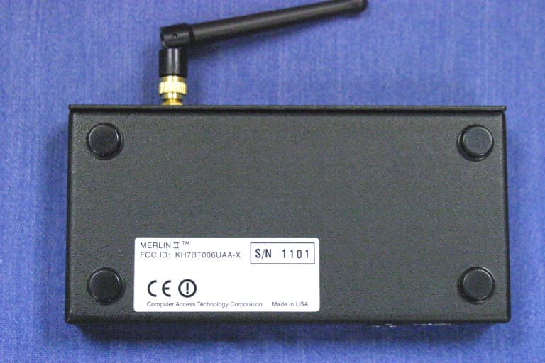
KH7BT006UAA-X
Jan 04, 2004Bluetooth Protocol Analyzer
Equipment Class
DSS - Part 15 Spread Spectrum Transmitter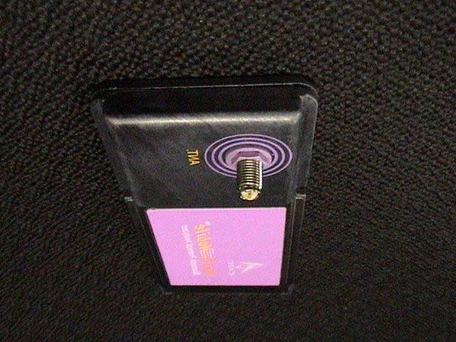
KH7BT005UAA-X
Aug 13, 2002Bluetooth Portable Protocol Analyzer
Equipment Class
DSS - Part 15 Spread Spectrum Transmitter
KH7-MRLN-A128
Nov 12, 2001Bluetooth Protocol Analyzer
Equipment Class
DSS - Part 15 Spread Spectrum TransmitterKH7AB0001
Jun 04, 1995Serial Bus Interface Card
Equipment Class
JBP - Part 15 Class B Computing Device PeripheralKH7P2AB-10
Aug 30, 1994External Access Bus Interface Device
Equipment Class
JBP - Part 15 Class B Computing Device Peripheral