KKGA040412DDS 12, DDT 12
Digital Control Inc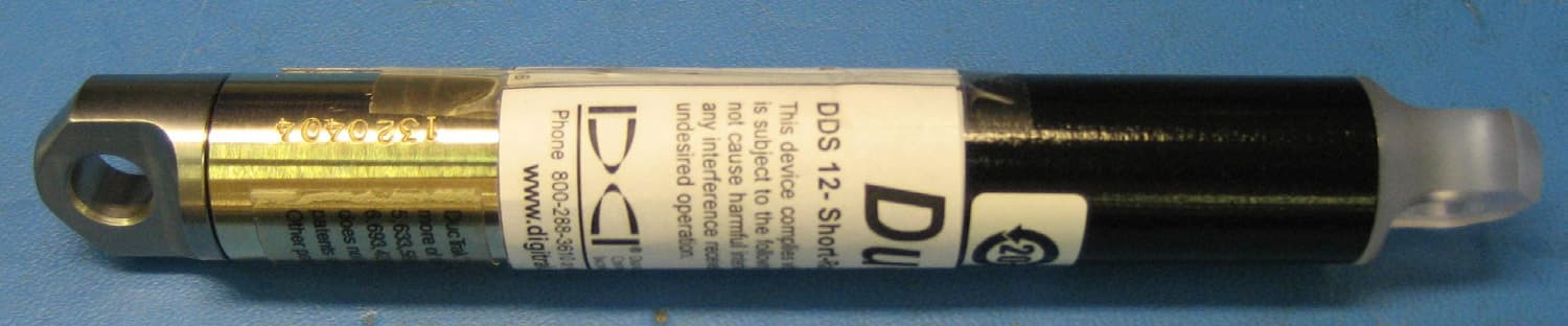
Click to zoom
Application Details
- Equipment Class
- DCD - Part 15 Low Power Transmitter Below 1705 kHz
- Date of Grant
- Sep 21, 2011
- Application Purpose
- Original Equipment
- Date of Application
- Sep 21, 2011
- Equipment Note
- DDS 12, DDT 12
- Frequency Range
- 0.01200000 - 0.01200000
- Company
- Digital Control Inc
- Country
- United States
Documents & Files
Document Text
Text extracted from the exhibit documents filed with the FCC. Open a document above to read the original.
Users Manual
Directional Drilling Locating System Operator’s Manual DIGITAL CONTROL INCORPORATED DCI Headquarters 19625 62nd Ave. S., Suite B-103 Kent, Washington 98032 USA Tel 425 251 0559 / 800 288 3610 Fax 253 395 2800 E-mail [email protected] www.digitrak.com DCI Europe Kurmainzer Strasse 56 D-97836 Bischbrunn Germany Tel +49(0) 9394 990 990 Fax +49(0) 9394 990 999 [email protected] DCI India DTJ 1023, DLF Tower A Jasola District Center New Delhi 110 044, India Tel +91(0) 11 4507 0444 Fax +91(0) 11 4507 0440 [email protected] DCI China No. 368, Xingle Road Huacao Town, Minhang District Shanghai P.R.C. 201107 Tel +86(0) 21 6432 5186 Fax +86(0) 21 6432 5187 [email protected] DCI Australia 2/9 Frinton Street Southport, Queensland 4215 Australia Tel +61(0) 7 5531 4283 Fax +61(0) 7 5531 2617 [email protected] DCI Russia 420059 Pavlyukhina Street 104, Kazan Russia Tel +7 843 277 52 22 Fax +7 843 277 52 07 [email protected] DIGITAL CONTROL INCORPORATED 2 DigiTrak ® F5™ Operator’s Manual 3-2500-00-C © 2010-2011 by Digital Control Incorporated. All rights reserved. June 2011. Trademarks The DCI logo, CableLink ® , DataLog ® , DigiTrak ® , Eclipse ® , F2 ® , iGPS ® , MFD ® , SST ® , target-in-the-box ® , Target Steering ® , and TensiTrak ® are U.S. registered trademarks and DucTrak™, F5™, F Series™, FSD™, FasTrak™, LT™, LT2™, LWD™, SE™, SED™, SuperCell™, and TeleLock™ are trademarks of Digital Control Incorporated. Limited Warranty All products manufactured and sold by Digital Control Incorporated (DCI) are subject to the terms of a Limited Warranty. A copy of the Limited Warranty is included at the end of this manual; it can also be obtained by contacting DCI Customer Service, 425-251-0559 or 800-288-3610, or by connecting to DCI's website, www.digitrak.com. Important Notice All statements, technical information, and recommendations related to the products of DCI are based on information believed to be reliable, but the accuracy or completeness thereof is not warranted. Before utilizing any DCI product, the user should determine the suitability of the product for its intended use. All statements herein refer to DCI products as delivered by DCI and do not apply to any user customizations not authorized by DCI nor to any third-party products. Nothing herein shall constitute any warranty by DCI nor will anything herein be deemed to modify the terms of DCI’s existing Limited Warranty applicable to all DCI products. FCC Compliance Statement This device complies with Part 15 of the Rules of the FCC. Operation is subject to the following two condi- tions: (1) this device may not cause harmful interference, and (2) this device must accept any interference received, including interference that may cause undesired operation. DCI is responsible for FCC compli- ance in the United States: Digital Control Incorporated, 19625 62nd Ave. S., Suite B-103, Kent, WA 98032; phone 425-251-0559 or 800-288-3610. Changes or modifications to the DCI equipment not expressly approved and carried out by DCI will void the user’s Limited Warranty and the FCC’s authorization to operate the equipment. CE Requirements DigiTrak receivers are classified as Class 2 radio equipment per the R&TTE Directive and may not be legal to operate or require a user license to operate in some countries. The list of restrictions and the required declarations of conformity are available on DCI’s website, www.digitrak.com, under the Service & Support tab. Click on DOWNLOADS and select from the CE Documents pull-down menu to download, view, or print the documents. DIGITAL CONTROL INCORPORATED DigiTrak ® F5™ Operator’s Manual 3 Table of Contents SAFETY PRECAUTIONS AND WARNINGS ................................................................................................ 6 DEAR CUSTOMER: ...................................................................................................................................... 8 INTRODUCTION ........................................................................................................................................... 9 RECEIVER .................................................................................................................................................. 11 General Description ................................................................................................................................. 11 Toggle and Trigger Switches ................................................................................................................... 12 Audible Tones .......................................................................................................................................... 12 Installing and Removing the Battery Pack............................................................................................... 12 Power On ................................................................................................................................................. 13 Power Off ................................................................................................................................................. 14 Main Menu ............................................................................................................................................... 14 Locate Mode ............................................................................................................................................ 16 Calibration Menu ..................................................................................................................................... 16 Height-Above-Ground (HAG) Menu ........................................................................................................ 17 Settings Menu .......................................................................................................................................... 18 Depth Units Menu…
Text truncated - open the document above for the full version.
Cover Letter(s)
Northwest EMC TCB Compliance Opinion Rev. 7/1/10 DIGC0145 Information about the Applicant Grantee (Company Name) Digital Control, Inc. FCC Contact Person Bruce E. Kolpak Address 19625 62nd Avenue South, Suite B103 City, State, Zip Kent, WA 98032 Job Number DIGC0145 Model DDS 12, DDT 12 FCC ID KKGA040412 Agent Approval Type Original Equipment Class DCD Part 15, low power Tx below 1.705 MHz Rule Part 15.209 Overview The Digital Controls, Inc.'s DucTrak 12 kHz magnetic field transmitter, models DDS 12 and DDT 12, are used to generate a constant 12 kHz tone, which is used to trace the path of existing duct work. The models are identical except for antenna length. The letter requesting exhibits to be held confidential long term is properly worded. No short term confidentiality requested. Recommendation All items have been resolved and completed to my satisfaction; therefore I recommend this application for approval. Signature Dave Tolman, TCB Committee 9/20/2011
External Photos
DDS 12 External Photos and label Side 1 Side 2 Label
External Photos
DDT 12 External Photos and label Side 1 Side 2 Label
ID Label/Location Info
THIS DRAWING IS CONFIDENTIAL AND IS SUPPLIED ON THE UNDERSTANDING THAT IT IS NOT SHOWN TO OTHER PERSONS OR COMPANIES WITHOUT THE WRITTEN CONSENT OF DIGITAL CONTROL INCORPORATED. Approval Approval Drafter Engineer By DateDescription TOLERANCES (Standard units unless otherwise specified) Decimal .X ±0.030 Fractions ±1/32 .XX ±0.010 .XXX ±0.005 Angles ±1° Title Drawing No. Sheet Rev. 19625 62nd Ave. S., Kent, WA 98032 425-251-0701 Fax 425-251-0702 www.digitrak.com DIGITAL CONTROL INCORPORATED ® DDS 12- Short-Range 2.4-3V 130mA Max This device complies with Part 15 of the FCC Rules. Operation is subject to the following two conditions: (1) this device may not cause harmful interference, and (2) this device must accept any interference received, including interference that may cause undesired operation. 2.75" 2.00" Instructions / Notes KH KH 7-8-03 Create new label per ECO 1066 Long-Range DucTrak ™ Transmitter 450-4101-00-01B 1/1 A DL 7-10-07 Removed Made In USA B 1 2 3 4 5 Dimensions Material Adhesive White Black 2.75" (W) x 2.00" (H); sharp radius GE: 8B35; Lexan; 7 mil thick; matted surface 3M: 468 MP; 5 mil adhesive; apply to back side Background flood All text and graphics Rev. DIGITAL CONTROL INCORPORATED ® www.digitrak.com Phone 800-288-3610 or 425-251-0559 DucTrak ™ ARBN 090 007 962 FCC ID: KKGA040412 IC: 2213A-A040412 12kHz Frequency 450-4202-00-01-B
ID Label/Location Info
THIS DRAWING IS CONFIDENTIAL AND IS SUPPLIED ON THE UNDERSTANDING THAT IT IS NOT SHOWN TO OTHER PERSONS OR COMPANIES WITHOUT THE WRITTEN CONSENT OF DIGITAL CONTROL INCORPORATED. Approval Approval Drafter Engineer By DateDescription TOLERANCES (Standard units unless otherwise specified) Decimal .X ±0.030 Fractions ±1/32 .XX ±0.010 .XXX ±0.005 Angles ±1° Title Drawing No. Sheet Rev. 19625 62nd Ave. S., Kent, WA 98032 425-251-0701 Fax 425-251-0702 www.digitrak.com DIGITAL CONTROL INCORPORATED ® DDT 12- Long-Range 2.4-3V 130mA Max This device complies with Part 15 of the FCC Rules. Operation is subject to the following two conditions: (1) this device may not cause harmful interference, and (2) this device must accept any interference received, including interference that may cause undesired operation. 2.75" 2.00" Instructions / Notes KH KH 7-8-03 Create new label per ECO 1066 Long-Range DucTrak ™ Transmitter 450-4101-00-01B 1/1 A DL 7-10-07 Removed Made In USA B 1 2 3 4 5 Dimensions Material Adhesive White Black 2.75" (W) x 2.00" (H); sharp radius GE: 8B35; Lexan; 7 mil thick; matted surface 3M: 468 MP; 5 mil adhesive; apply to back side Background flood All text and graphics Rev. DIGITAL CONTROL INCORPORATED ® www.digitrak.com Phone 800-288-3610 or 425-251-0559 DucTrak ™ ARBN 090 007 962 FCC ID: KKGA040412 IC: 2213A-A040412 12kHz Frequency 450-4201-00-01-B
Internal Photos
DDS 12 Internal Transmitter Photos Power supply PCB top and bottom Transmitter PCB top and bottoms PCB assembly with antenna assembly (antenna and capacitor shown above are what is inside the small potted tube)
Internal Photos
DDT 12 Internal Transmitter Photos Power supply PCB top and bottom Transmitter PCB top and bottoms PCB assembly with antenna assembly (antenna and capacitor shown above are what is inside the long potted tube)
Test Report
Digital Control, Inc. DucTrak Model DDS 12 Model DDT 12 (short and long) Report No. DIGC0145 Report Prepared By www.nwemc.com 1-888-EMI-CERT © 2011 Northwest EMC, Inc 22975 NW Evergreen Parkway Suite 400 Hillsboro, Oregon 97124 Certificate of Test Last Date of Test: August 24, 2011 Digital Control, Inc. Models: DucTrak DDS 12, DDT 12 (short and long) Emissions Test Description Specification Test Method Pass/Fail Field Strength of Fundamental FCC 15.209:2011 ANSI C63.10:2009 Pass Field Strength of Spurious Emissions FCC 15.209:2011 ANSI C63.10:2009 Pass Modifications made to the product See the Modifications section of this report Test Facility The measurement facility used to collect the data is located at: Northwest EMC, Inc. 22975 NW Evergreen Parkway, Suite 400 Hillsboro, OR 97124 Phone: (503) 844-4066 Fax: 844-3826 This site has been fully described in a report filed with and accepted by the FCC (Federal Communications Commission) and Industry Canada (Site filing #2834D-1). Approved By: Tim O'Shea, Operations Manager NVLAP Lab Code: 200630-0 This report must not be used to claim product certification, approval, or endorsement by NVLAP, NIST, or any agency of the federal government of the United States of America. Product compliance is the responsibility of the client, therefore the tests and equipment modes of operation represented in this report were agreed upon by the client, prior to testing. This Report may only be duplicated in its entirety. The results of this test pertain only to the sample(s) tested. The specific description is noted in each of the individual sections of the test report supporting this certificate of test. Northwest EMC Revision History Revision 06/29/09 Barometric Pressure The recorded barometric pressure has been normalized to sea level. Revision Number Description Date Page Number 00 None Accreditations and Authorizations FCC Accredited by NVLAP for performance of FCC radio, digital, and ISM device testing. Our Open Area Test Sites, certification chambers, and conducted measurement facilities have been fully described in reports filed with the FCC and accepted by the FCC in letters maintained in our files. Northwest EMC has been accredited by ANSI to ISO / IEC Guide 65 as a product certifier. We have been designated by the FCC as a Telecommunications Certification Body (TCB). This allows Northwest EMC to certify transmitters to FCC specifications in accordance with 47 CFR 2.960 and 2.962. NVLAP Northwest EMC, Inc. is accredited under the National Voluntary Laboratory Accreditation Program (NVLAP) for satisfactory compliance with the requirements of ISO/IEC 17025 for Testing Laboratories. NVLAP is administered by the National Institute of Standards and Technology (NIST), an agency of the U.S. Commerce Department. The NVLAP accreditation encompasses Electromagnetic Compatibility Testing in accordance with the European Union EMC Directive 2004/108/EC, and ANSI C63.4. Additionally, Northwest EMC is accredited by NVLAP to perform radio testing in accordance with the European Union R&TTE Directive 1999/5/EEC, the requirements of FCC, and the RSS radio standards for Industry Canada. Industry Canada Accredited by NVLAP for performance of Industry Canada RSS and ICES testing. Our Open Area Test Sites and certification chambers comply with RSS-Gen, Issue 2 and have been filed with Industry Canada and accepted. Northwest EMC has been accredited by ANSI to ISO / IEC Guide 65 as a product certifier. We have been designated by NIST and recognized by Industry Canada as a Certification Body (CB) per the APEC Mutual Recognition Arrangement (MRA). This allows Northwest EMC to certify transmitters to Industry Canada technical requirements. (Site Filing Numbers - Hillsboro: 2834D-1, 2834D-2, Sultan: 2834C-1, Irvine: 2834B-1, 2834B-2, Brooklyn Park: 2834E-1) CAB Designated by NIST and validated by the European Commission as a Conformity Assessment Body (CAB) to conduct tests and approve products to the EMC directive and transmitters to the R&TTE directive, as described in the U.S. - EU Mutual Recognition Agreement. Australia/New Zealand The National Association of Testing Authorities (NATA), Australia has been appointed by the ACA as an accreditation body to accredit test laboratories and competent bodies for EMC standards. Accredited test reports or assessments by competent bodies must carry the NATA logo. Test reports made by an overseas laboratory that has been accredited for the relevant standards by an overseas accreditation body that has a Mutual Recognition Agreement (MRA) with NATA are also accepted as technical grounds for product conformity. The report should be endorsed with the respective logo of the accreditation body (NVLAP). Accreditations and Authorizations VCCI Accepted as an Associate Member to the VCCI, Acceptance No. 564. Conducted and radiated measurement facilities have been registered in accordance with Regulations for Voluntary Control Measures, Article 8. (Registration Numbers. - Hillsboro: C-1071, R-1025, G-84, C-2687, T- 1658, and R-2318, Irvine: R-1943, G-85, C-2766, and T-1659, Sultan: R-871, G-83, C-3265, and T-1511, Brooklyn Park: R-3125, G-86, G-141, C-3464, and T-1634). BSMI Northwest EMC has been designated by NIST and validated by C-Taipei (BSMI) as a CAB to conduct tests as described in the APEC Mutual Recognition Agreement (US0017). GOST Northwest EMC, Inc. has been assessed and accredited by the Russian Certification bodies Certinform VNIINMASH, CERTINFO, SAMTES, and Federal CHEC, to perform EMC and Hygienic testing for Information Technology Products. As a result of their laboratory assessment, they will accept test results from Northwest EMC, Inc. for product certification KCC Northwest EMC, Inc is a CAB designated by MRA partners and recognized by Korea. (Assigned Lab Numbers: Hillsboro: US0017, Irvine: US0158, Sultan: US0157, Brooklyn Park: US0175) VIETNAM Vietnam MIC has approved Northwest EMC as an accredited test lab. Per Decision N…
Text truncated - open the document above for the full version.
Test Setup Photos
NORTHWEST EMC FF long 01.jpg FF long 02.jpg Field Strength of Fundamental PSA-ESCI 2011.07.26 NORTHWEST EMC FF short 01.jpg FF Short 02.jpg Field Strength of Fundamental PSA-ESCI 2011.07.26 NORTHWEST EMC OBB 01.jpg OBB 02.jpg Occupied Bandwidth XMit 2010.11.03 NORTHWEST EMC FF long 01.jpg FF long 02.jpg Field Strength of Spurious Emissions PSA-ESCI 2011.07.26 NORTHWEST EMC FF short 01.jpg FF Short 02.jpg Field Strength of Spurious Emissions PSA-ESCI 2011.07.26
Contact Information
Applicant
Thomas J. Hall(General Counsel)
Test Firm
Northwest EMC, Inc.Greg Kiemel
Technical Specifications
| # | Rule Parts | Frequency Range | Power Output |
|---|---|---|---|
| 1 | 15C | 0.012 MHz - 0.012 MHz | - |
Other Applications from Digital Control Inc
KKGB2DIG1
Aug 28, 2013DR2
Equipment Class
TNB - Licensed Non-Broadcast Station Transmitter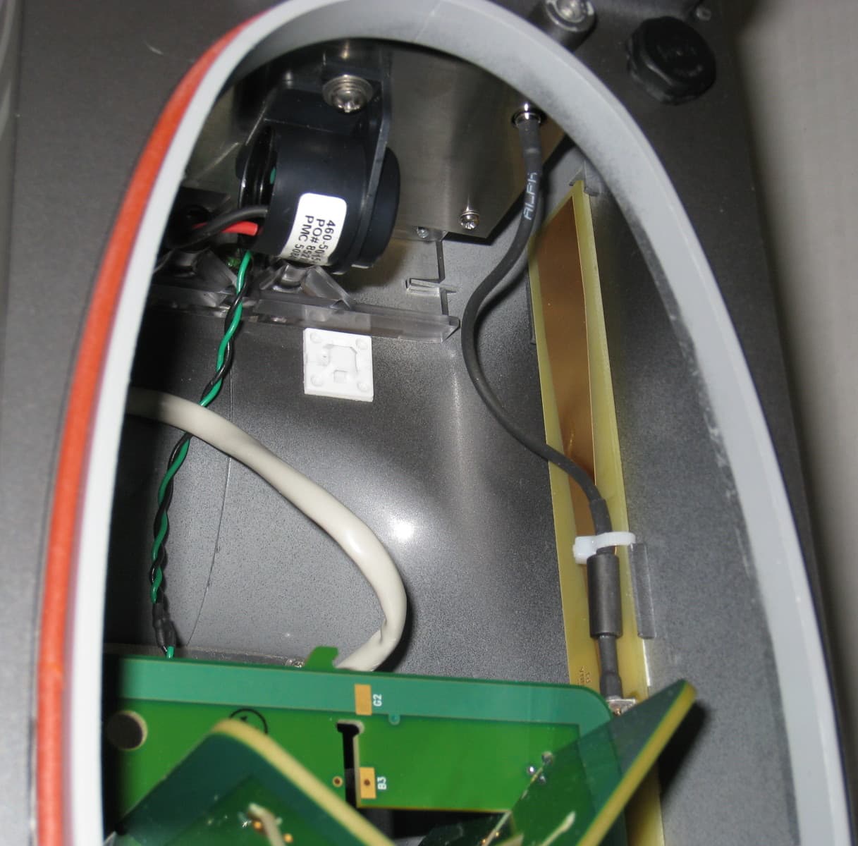
KKGB1DIG1
Jul 11, 2011DigiRadio
Equipment Class
TNB - Licensed Non-Broadcast Station Transmitter
KKG50416
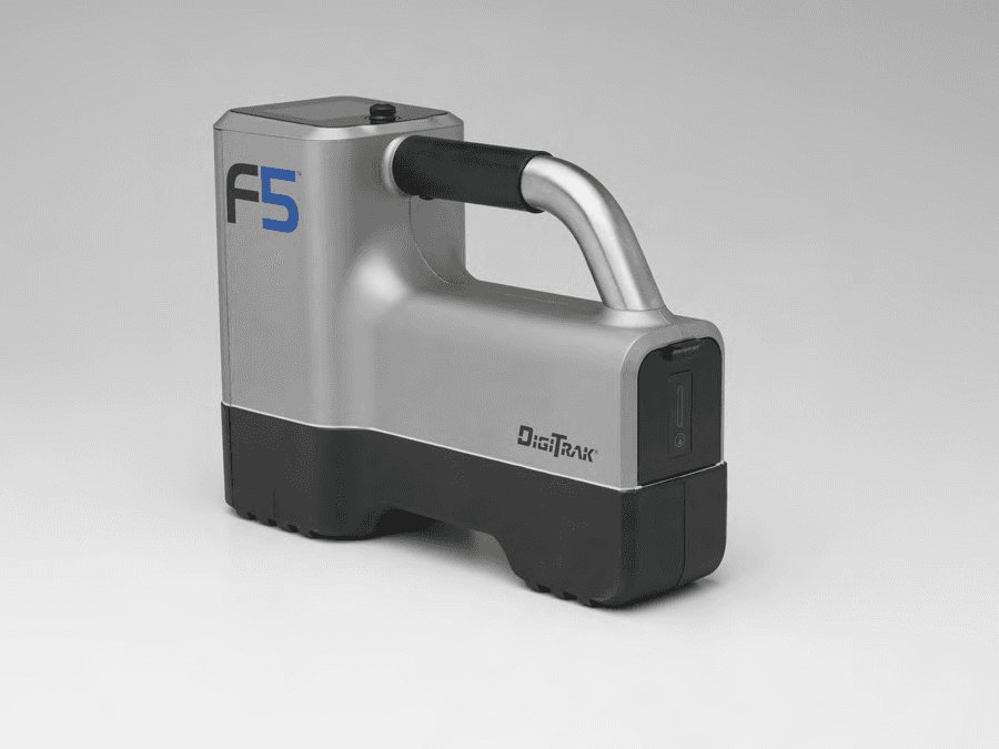
Apr 13, 2011F5Dp 19/12, F5Dp 12/1.3, F5DLp 19/12
Equipment Class
DCD - Part 15 Low Power Transmitter Below 1705 kHz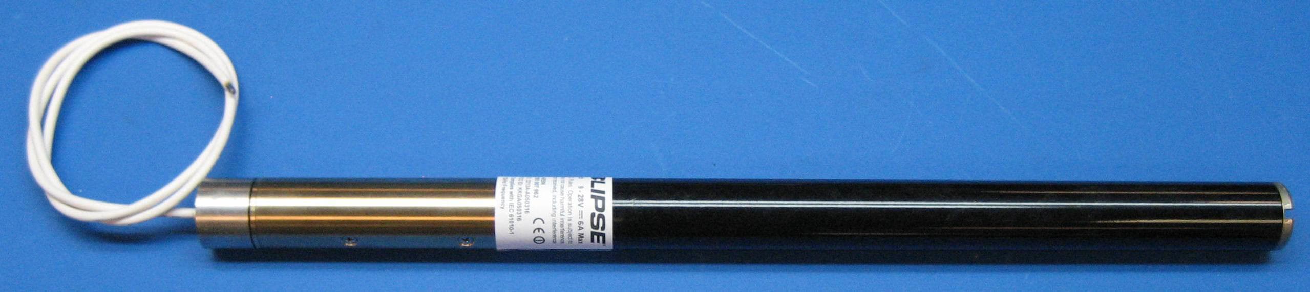
KKGA050316
Apr 03, 2011ECP, FC
Equipment Class
DCD - Part 15 Low Power Transmitter Below 1705 kHz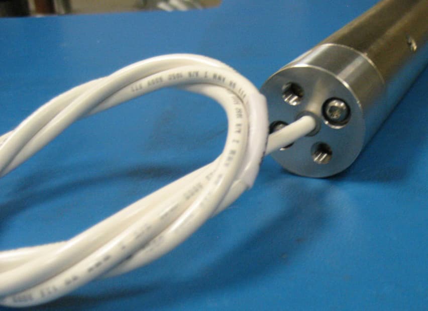
KKGA191920
Apr 03, 2011SST, SST5
Equipment Class
DCD - Part 15 Low Power Transmitter Below 1705 kHz