KKGB2DIG1DR2
Digital Control Inc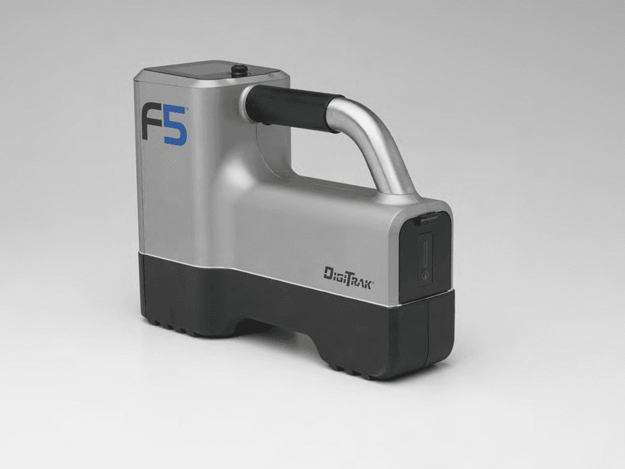
Click to zoom
Application Details
- Equipment Class
- TNB - Licensed Non-Broadcast Station Transmitter
- Date of Grant
- Aug 28, 2013
- Application Purpose
- Original Equipment
- Date of Application
- Aug 28, 2013
- Equipment Note
- DR2
- Frequency Range
- 464.50000000 - 469.55000000
- Company
- Digital Control Inc
- Country
- United States
Documents & Files
Document Text
Text extracted from the exhibit documents filed with the FCC. Open a document above to read the original.
Users Manual
DIGITAL CONTROL INCORPORATED 19625 62nd Ave S, Suite B103 Kent Washington 98032, USA 425.251.0559 / 800.288.3610 [email protected], www.DigiTrak.com Australia – China – Germany – India – Russia F5 Directional Drilling Locating System Operator’s Manual ® DIGITAL CONTROL INCORPORATED ii DigiTrak F5 Operator’s Manual 403-2500-00-E, 5/2013 © 2010-2013 by Digital Control Incorporated. All rights reserved. Trademarks The DCI logo, CableLink ® , DataLog ® , DigiTrak ® , Eclipse ® , F2 ® , F5 ® , iGPS ® , MFD ® , SST ® , target-in-the-box ® , Target Steering ® , and TensiTrak ® are U.S. registered trademarks and DucTrak™, FBC™, FBP™, F Series™, FSD™, FasTrak™, LWD™, SBP™, SE™, SED™, SuperCell™, and TeleLock™ are trademarks of Digital Control Incorporated. Limited Warranty All products manufactured and sold by Digital Control Incorporated (DCI) are subject to the terms of a Limited Warranty. A copy of the Limited Warranty is included at the end of this manual; it can also be obtained by contacting DCI Customer Service, 425-251-0559 or 800-288-3610, or at DCI's website, www.digitrak.com. Important Notice All statements, technical information, and recommendations related to the products of DCI are based on information believed to be reliable, but the accuracy or completeness thereof is not warranted. Before utilizing any DCI product, the user should determine the suitability of the product for its intended use. All statements herein refer to DCI products as delivered by DCI and do not apply to any user customizations not authorized by DCI nor to any third-party products. Nothing herein shall constitute any warranty by DCI nor will anything herein be deemed to modify the terms of DCI’s existing Limited Warranty applicable to all DCI products. The most recent version of this manual is available on DCI's website. FCC Compliance Statement This equipment complies with Part 15 of the Rules of the FCC and with Industry Canada license-exempt RSS standards and with Australia Class License 2000 for LIPD (low interference potential devices). Operation is subject to the following two conditions: (1) this equipment may not cause harmful interference, and (2) this equipment must accept any interference received, including interference that may cause undesired operation. DCI is responsible for FCC compliance in the United States: Digital Control Incorporated, 19625 62nd Ave S, Suite B103, Kent WA 98032; phone 425-251-0559 or 800-288-3610. Changes or modifications to any DCI equipment not expressly approved and carried out by DCI will void the user’s Limited Warranty and the FCC’s authorization to operate the equipment. CE Requirements DigiTrak receivers are classified as Class 2 radio equipment per the R&TTE Directive and may not be legal to operate or require a user license to operate in some countries. The list of restrictions and the required declarations of conformity are available on DCI’s website, www.digitrak.com, under the Service & Support tab. Click on DOWNLOADS and select from the CE Documents pull-down menu to download, view, or print the documents. DIGITAL CONTROL INCORPORATED DigiTrak F5 Operator’s Manual iii Dear Customer, Thank you for choosing the DigiTrak F5 Locating System. We are extremely proud of the equipment we have been designing and building in Washington State since 1990. We believe in providing a unique, high-quality product and standing behind it with superior customer service and training. Please take the time to read this entire manual, especially the section on safety. Also, please fill in the product registration card provided with this equipment and either mail it to DCI headquarters, fax it to us at 253-395-2800, or complete and submit the form online at our website. We will put you on the Digital Control mailing list and send you product upgrade information and our FasTrak newsletter. Feel free to contact us if you have any problems or questions. Our Customer Service department is available 24 hours a day, 7 days a week. As the horizontal directional drilling industry grows, we’re keeping our eye on the future to develop equipment that will make your job faster and easier. Visit our website any time to see what we’re up to. We welcome your questions, comments, and ideas. Digital Control Incorporated Kent, Washington 2013 See our DigiTrak Training Videos on YouTube at www.youtube.com/dcikent. DIGITAL CONTROL INCORPORATED iv DigiTrak F5 Operator’s Manual Table of Contents Safety Precautions and Warnings vii Introduction ix Receiver xi General Description ......................................................................................... xi Toggle and Trigger Switches .......................................................................... xii Audible Tones ................................................................................................. xii Installing and Removing the Battery Pack ...................................................... xii Power On ...................................................................................................... xiii Using the Keypad .......................................................................................... xiv Main Menu .................................................................................................... xiv Locate Mode ........................................................................................... xv Power Off .............................................................................................. xvi Calibration Menu .................................................................................... xvi Height-Above-Ground (HAG) Menu ........................................................... xvi Settings Menu ........................................................................................ xvi Transmitter Selection Menu ...................................................................... xx Drill DataLog Menu ...........................................…
Text truncated - open the document above for the full version.
Cover Letter(s)
WTD 13.4.9 FCC Compliance Opinion DIGC0168 Information about the Applicant Grantee (Company Name) Digital Control, Inc. FCC Contact Person Thomas J. Hall Address 19625 62nd Avenue South, Suite B103 City, State, Zip Kent, WA 98032 Job Number DIGC0168 Model DigiRadio model DR2 FCC ID KKGB2DIG1 Agent Bruce E. Kolpack Approval Type Original Equipment Class TNB Licensed Non-Broadcast Base Station Transmitter Rule Part licensed 90 Overview This application is for the limited modular approval of the Model DR2 DigiRadio module. The DR2 is designed to be used in DigiTrak brand devices to transmit and receive telemetry data during horizontal directional drilling applications. The device will be installed in the applicants host device at the factory and users do not have access to alter any of the factory settings or the radio. Confidentiality requested for allowed files. Request is properly addressed and referenced. A letter listing the applicable modular requirements was submitted. Recommendation All items have been resolved and completed to my satisfaction; therefore I recommend this application for approval. Signature Dave Tolman, TCB Committee 8/26/2013
External Photos
DigiRadio 2 (DR2) External Photos DR2 Host Device – F5R DR2 Antenna DR2 – Installed in F5R Host Device with Antenna DR2 Antenna DR2 – Mounted on F5R Host Board with Shielding DR2 – Mounted on F5R Host Board DR2 DR2 – F5R Host Board
ID Label/Location Info
F5 Receiver (F5R) Label and Location Labels are located inside the battery compartment Remove battery to view labels inside battery compartment Labels shown inside battery compartment Label close ups
ID Label/Location Info
DigiRadio2 (DR2) Module Labeling
Internal Photos
DigiRadio 2 (DR2) Internal Photos DR2 – Top Si4464 Wireless Transceiver STM32F103CB Microcontroller DR2 – Bottom Antenna Connector Host Connector
Operational Description
Statement from Digital Control Incorporated: The DigiRadio™2 module (model DR2), designed for use in DigiTrak® brand handheld receivers (UHF transmitter) and remote displays (UHF receiver), is installed in the host devices at the manufacturer. The antenna used in the UHF transmitter host devices is also installed at the manufacturer. The maximum gain of the antenna used with the DR2 module is 0.1 dBi. The antenna drawing is shown below. Note the antenna type is: dipole.
Parts List/Tune Up Info
DigiRadio2 (DR2) Tuning Attestation from Digital Control: Currently we do not do any tuning of the DigiRadio2 module, model DR2. The DR2 relies on the host device to program the specific carrier frequency. We verify its functionality by making sure we can pick up the transmitted signal using a receiver tuned to the same frequency. While there are provisions in the Si4464 to adjust the Load Capacitance and Frequency Offset of the Local Oscillator, the DR2 uses a high precision Temperature Compensated Crystal Oscillator (TCXO) that does not require fine-tuning. Default values are hardcoded into the DigiRadio2 firmware and cannot be changed by the host device. Basically, the radio either works or it doesn’t.
RF Exposure Info
Digital Control, Inc. DigiRadio 2 (DR2) Report #: DIGC0168.2 FCC 2.1091: Maximum Permissible Exposure Level Report Prepared By Northwest EMC Inc. NORTHWEST EMC – (888) 364-2378 – www.nwemc.com California – Minnesota – Oregon – New York – Washington WTD 12.5.23 CERTIFICATE OF TEST Certificate of Evaluation Date of Evaluation June 26, 2013 Digital Control, Inc. Model: DigiRadio 2 (DR2) Emissions Test Description SpecificationTest MethodPass/Fail Maximum Permissible Exposure FCC 2.1091:2013 OET Bulletin 65, Supplement C Ed 01-01 Pass Deviations From Test Standards None Approved By: Don Facteau, IS Manager NVLAP Lab Code: 200630-0 This report must not be used to claim product certification, approval, or endorsement by NVLAP, NIST, or any agency of the federal government of the United States of America. Product compliance is the responsibility of the client, therefore the tests and equipment modes of operation represented in this report were agreed upon by the client, prior to testing. This Report may only be duplicated in its entirety. The results of this test pertain only to the sample(s) tested. The specific description is noted in each of the individual sections of the test report supporting this certificate of test. Report No. DIGC0168.22/9 REV 2012.05.24 REVISION HISTORY Revision Number Description Date Page Number 00 None Report No. DIGC0168.23/9 REV 2012.05.24 ACCREDITATIONS AND AUTHORIZATIONS United States FCC - Designated by the FCC as a Telecommunications Certification Body (TCB). Certification chambers, Open Area Test Sites, and conducted measurement facilities are listed with the FCC. A2LA - Accredited by A2LA to ISO / IEC Guide 65 as a product certifier. This allows Northwest EMC to certify transmitters to FCC and IC specifications. NVLAP - Each laboratory is accredited by NVLAP to ISO 17025 Canada IC - Recognized by Industry Canada as a Certification Body (CB). Certification chambers and Open Area Test Sites are filed with IC. European Union European Commission – Validated by the European Commission as a Conformity Assessment Body (CAB) under the EMC directive and as a Notified Body under the R&TTE Directive. Australia/New Zealand ACMA - Recognized by ACMA as a CAB for the acceptance of test data. Korea KCC / RRA - Recognized by KCC’s RRA as a CAB for the acceptance of test data. Japan VCCI - Associate Member of the VCCI. Conducted and radiated measurement facilities are registered. Taiwan BSMI – Recognized by BSMI as a CAB for the acceptance of test data. NCC - Recognized by NCC as a CAB for the acceptance of test data. Singapore IDA – Recognized by IDA as a CAB for the acceptance of test data. Hong Kong OFTA – Recognized by OFTA as a CAB for the acceptance of test data. Vietnam MIC – Recognized by MIC as a CAB for the acceptance of test data. Russia GOST – Accredited by Certinform VNIINMASH, CERTINFO, SAMTES, and Federal CHEC to perform EMC and Hygienic testing for Information Technology products to GOST standards. SCOPE For details on the Scopes of our Accreditations, please visit: http://www.nwemc.com/accreditations/ Report No. DIGC0168.24/9 REV 2013.01.07 LOCATIONS Oregon Labs EV01-12 22975 NW Evergreen Pkwy Hillsboro, OR 97124 (503) 844-4066 California Labs OC01-13 41 Tesla Irvine, CA 92618 (949) 861-8918 New York Labs WA01-04 4939 Jordan Rd. Elbridge, NY 13060 (315) 685-0796 Minnesota Labs MN01-08 9349 W Broadway Ave. Brooklyn Park, MN 55445 (763) 425-2281 Washington Labs NC01-05,SU02,SU07 19201 120 th Ave. NE Bothell, WA 98011 (425) 984-6600 VCCI A-0108 A-0029 A-0109 A-0110 Industry Canada 2834D-1, 2834D-2 2834B-1, 2834B-2, 2834B-3 2834E-1 2834C-1 Report No. DIGC0168.25/9 WTD 12.5.23 PRODUCT DESCRIPTION Client and Equipment Under Test (EUT) Information Company Name: Digital Control Incorporated. Address: 19625 62nd Avenue South, Suite B103 City, State, Zip: Kent, WA 98032 Test Requested By: Amanda Hamm Model: DigiRadio2 (DR2) Information Provided by the Party Requesting the Test Functional Description of the EUT (Equipment Under Test): FM at 9600 bps (4800 Manchester bps) with an output power of 100mW. Operating at 464.5-469.55 MHz Testing Objective: To demonstrate compliance with FCC requirements for RF exposure for 2.1091 mobile devices Report No. DIGC0168.26/9 WD.12.29.11 Maximum Permissible Exposure (MPE) OVERVIEW Human exposure to RF emissions from mobile devices (47 CFR §2.1091) may be evaluated based on the MPE limits adopted by the FCC for electric and magnetic field strength and/or power density, as appropriate, since exposures are assumed to occur at distances of 20 cm or more from persons. ANSI C95.1-1992 specifies a minimum separation distance of 20 cm for performing reliable field measurements to determine adherence to MPE limits. If the minimum separation distance between a transmitter and nearby persons is more than 20 cm under normal operating conditions, compliance with MPE limits may be determined at such distance from the transmitter. When applicable, operation instructions and prominent warning labels may be used to alert the exposed persons to maintain a specified distance from the transmitter or to limit their exposure durations and usage conditions to ensure compliance. If the use of warning labels on a transmitter is not effective or desirable, the alternative of performing SAR evaluation with the device at its closest range to persons under normal operating conditions may be used. The field strength and power density limits adopted by the FCC are based on whole-body averaged exposure and the assumption of RF field levels relate most accurately to estimating whole-body averaged SAR. This means some local values of exposures exceeding the stated field strength and power density limits may not necessarily imply non-compliance if the spatial average of spatially averaged RF fields over the exposed portions of a person’s body does not exceed the limits. COMPLIANCE WITH 2.1091 “Mobile devices that operate in the Cellular Radiotelephone Service, the Pe…
Text truncated - open the document above for the full version.
Test Report
Digital Control Incorporated DigiRadio 2 (DR2) FCC 90.217:2013 FCC 15.109:2013 Report #: DIGC0168 Report Prepared By Northwest EMC Inc. NORTHWEST EMC – (888) 364-2378 – www.nwemc.com California – Minnesota – Oregon – New York – Washington WTD 12.5.23 CERTIFICATE OF TEST Last Date of Test: August 5, 2013 Digital Control Incorporated Model: DigiRadio 2 (DR2) Emissions Test Description Specification Test Method Pass/Fail Occupied Bandwidth FCC 90.217:2013 ANSI/TIA/EIA-603-C-2004 Pass Emissions Mask FCC 90.217:2013 ANSI/TIA/EIA-603-C-2004 Pass Radiated Output Power FCC 90.217:2013 ANSI/TIA/EIA-603-C-2004 Pass Output Power FCC 90.217:2013 ANSI/TIA/EIA-603-C-2004 Pass Frequency Stability FCC 90.217:2013 ANSI/TIA/EIA-603-C-2004 Pass Spurious Conducted Emissions FCC 90.217:2013 ANSI/TIA/EIA-603-C-2004 Pass Receiver Spurious Emissions FCC 15.109:2013 ANSI C63.4:2009 Pass Transmitter Spurious Emissions FCC 90.217:2013 ANSI/TIA/EIA-603-C:2004 Pass Deviations From Test Standards None Approved By: Tim O'Shea, Operations Manager NVLAP Lab Code: 200630-0 Test Facility The measurement facility used to collect the data is located at: Northwest EMC, Inc. 22975 NW Evergreen Parkway, Suite 400 Hillsboro, OR 97124 Phone: (503) 844-4066 Fax: 844-3826 This site has been fully described in a report filed with and accepted by the FCC (Federal Communications Commission) and Industry Canada (Site filing #2834D-1). This report must not be used to claim product certification, approval, or endorsement by NVLAP, NIST, or any agency of the federal government of the United States of America. Product compliance is the responsibility of the client, therefore the tests and equipment modes of operation represented in this report were agreed upon by the client, prior to testing. This Report may only be duplicated in its entirety. The results of this test pertain only to the sample(s) tested. The specific description is noted in each of the individual sections of the test report supporting this certificate of test. REV 2012.08.02 REVISION HISTORY Revision Number Description Date Page Number 00 None Barometric Pressure The recorded barometric pressure has been normalized to sea level. REV 2013.03.8 MEASUREMENT UNCERTAINTY Measurement Uncertainty When a measurement is made, the result will be different from the true or theoretically correct value. The difference is the result of tolerances in the measurement system that cannot be completely eliminated. To the extent that technology allows us, it has been our aim to minimize this error. Measurement uncertainty is a statistical expression of measurement error qualified by a probability distribution. A measurement uncertainty estimation has been performed for each test per our internal quality document WP 342. The estimation is used to compare the measured result with its "true" or theoretically correct value. The expanded measurement uncertainty (K=2) for each test is listed below. Our measurement data meets or exceeds the measurement uncertainty requirements of the applicable specification; therefore, the test data can be compared directly to the specification limit to determine compliance. The calculations for estimating measurement uncertainty are based upon ETSI TR 100 028 (or CISPR 16-4-1 as applicable), and are available upon request. The following table represents the Measurement Uncertainty (MU) budgets for each of the tests that may be contained in this report. Test + MU - MU Frequency Accuracy (Hz) 0.12 -0.01 Amplitude Accuracy (dB) 0.49 -0.49 Conducted Power (dB) 0.41 -0.41 Radiated Power via Substitution (dB) 0.69 -0.68 Temperature (degrees C) 0.81 -0.81 Humidity (% RH) 2.89 -2.89 Field Strength (dB) 3.80 -3.80 AC Powerline Conducted Emissions (dB) 2.94 -2.94 REV 2012.05.24 ACCREDITATIONS AND AUTHORIZATIONS United States FCC - Designated by the FCC as a Telecommunications Certification Body (TCB). Certification chambers, Open Area Test Sites, and conducted measurement facilities are listed with the FCC. A2LA - Accredited by A2LA to ISO / IEC Guide 65 as a product certifier. This allows Northwest EMC to certify transmitters to FCC and IC specifications. NVLAP - Each laboratory is accredited by NVLAP to ISO 17025 Canada IC - Recognized by Industry Canada as a Certification Body (CB). Certification chambers and Open Area Test Sites are filed with IC. European Union European Commission – Validated by the European Commission as a Conformity Assessment Body (CAB) under the EMC directive and as a Notified Body under the R&TTE Directive. Australia/New Zealand ACMA - Recognized by ACMA as a CAB for the acceptance of test data. Korea KCC / RRA - Recognized by KCC’s RRA as a CAB for the acceptance of test data. Japan VCCI - Associate Member of the VCCI. Conducted and radiated measurement facilities are registered. Taiwan BSMI – Recognized by BSMI as a CAB for the acceptance of test data. NCC - Recognized by NCC as a CAB for the acceptance of test data. Singapore IDA – Recognized by IDA as a CAB for the acceptance of test data. Hong Kong OFTA – Recognized by OFTA as a CAB for the acceptance of test data. Vietnam MIC – Recognized by MIC as a CAB for the acceptance of test data. Russia GOST – Accredited by Certinform VNIINMASH, CERTINFO, SAMTES, and Federal CHEC to perform EMC and Hygienic testing for Information Technology products to GOST standards. SCOPE For details on the Scopes of our Accreditations, please visit: http://www.nwemc.com/accreditations/ REV 2013.02.26 LOCATIONS Oregon Labs EV01-12 22975 NW Evergreen Pkwy Hillsboro, OR 97124 (503) 844-4066 California Labs OC01-13 41 Tesla Irvine, CA 92618 (949) 861-8918 New York Labs NY01-04 4939 Jordan Rd. Elbridge, NY 13060 (315) 685-0796 Minnesota Labs MN01-08 9349 W Broadway Ave. Brooklyn Park, MN 55445 (763) 425-2281 Washington Labs NC01-05,SU02,SU07 19201 120 th Ave. NE Bothell, WA 98011 (425) 984-6600 VCCI A-0108 A-0029 A-0109 A-0110 Industry Canada 2834D-1, 2834D-2 2834B-1, 2834B-2, 2834B-3 2834E-1 2834C-1 NVLAP NVLAP Lab …
Text truncated - open the document above for the full version.
Test Setup Photos
OCCUPIED BANDWIDTH XMit 2013.02.28 NORTHWEST OCCUPIED BANDWID EMC EV06 -1.JPG EV06 -2.JPG OCCUPIED BANDWIDTH EMISSION MASK XMit 2013.02.28 NORTHWEST EMISSION MASK EMC EV06 -1.JPG EV06 -2.JPG EMISSION MASK photo DIGC0168 SRE Horizontal 002.JPG DIGC0168 SRE Horizontal 003.JPG RADIATED OUTPUT POWER PSA-ESCI 2012.12.14 photo DIGC0168 SRE Horizontal 004.JPG DIGC0168 SRE On Side 003.JPG RADIATED OUTPUT POWER PSA-ESCI 2012.12.14 photo DIGC0168 SRE Vertical 001.JPG RADIATED OUTPUT POWER PSA-ESCI 2012.12.14 OUTPUT POWER XMit 2013.02.28 NORTHWEST OUTPUT POWER EMC EV06 -1.JPG EV06 -2.JPG OUTPUT POWER FREQUENCY STABILITY XMit 2013.02.28 NORTHWEST FREQUENCY STABILI EMC EV06 -1.JPG EV06 -2.JPG FREQUENCY STABILITY FREQUENCY STABILITY XMit 2013.02.28 NORTHWEST FREQUENCY STABILI EMC EV09 -2.JPG EV09 -3.JPG FREQUENCY STABILITY SPURIOUS CONDUCTED EMISSIONS XMit 2013.02.28 NORTHWEST SPURIOUS CONDUCT EMC EV06 -1.JPG EV06 -2.JPG SPURIOUS CONDUCTED EMISSIONS photo DIGC0168 SRE Horizontal 003.JPG DIGC0168 SRE Horizontal 004.JPG Receiver Spurious Emissions PSA-ESCI 2012.12.14 photo DIGC0168 SRE On Side 003.JPG DIGC0168 SRE Vertical 001.JPG Receiver Spurious Emissions PSA-ESCI 2012.12.14 photo DIGC0168 SRE Horizontal 002.JPG Receiver Spurious Emissions PSA-ESCI 2012.12.14 photo DIGC0168 SRE Vertical 001.JPG DIGC0168 SRE Horizontal 002.JPG Transmitter Spurious Emissions PSA-ESCI 2012.12.14 photo DIGC0168 SRE Horizontal 003.JPG DIGC0168 SRE Horizontal 004.JPG Transmitter Spurious Emissions PSA-ESCI 2012.12.14 photo DIGC0168 SRE On Side 003.JPG Transmitter Spurious Emissions PSA-ESCI 2012.12.14
Contact Information
Applicant
Thomas J. Hall(General Counsel)
Test Firm
Northwest EMC, Inc.Greg Kiemel
Technical Specifications
| # | Rule Parts | Frequency Range | Power Output | Emission | Tolerance |
|---|---|---|---|---|---|
| 1 | 90.217(b) | 464.5 MHz - 469.55 MHz | 107.00 mW | 10K2F1D | 0.8000000000 ppm |
Other Applications from Digital Control Inc
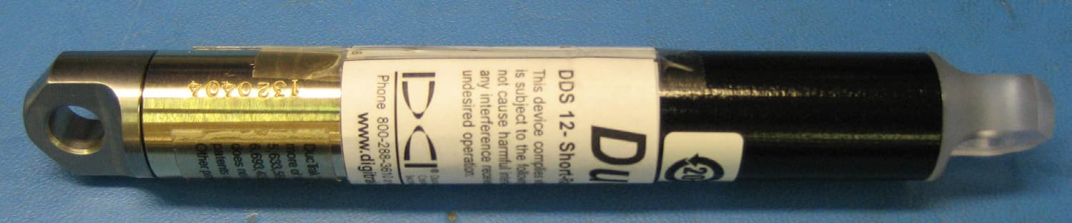
KKGA040412
Sep 21, 2011DDS 12, DDT 12
Equipment Class
DCD - Part 15 Low Power Transmitter Below 1705 kHz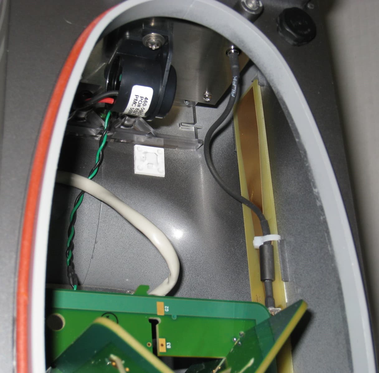
KKGB1DIG1
Jul 11, 2011DigiRadio
Equipment Class
TNB - Licensed Non-Broadcast Station Transmitter
KKG50416
Apr 13, 2011F5Dp 19/12, F5Dp 12/1.3, F5DLp 19/12
Equipment Class
DCD - Part 15 Low Power Transmitter Below 1705 kHz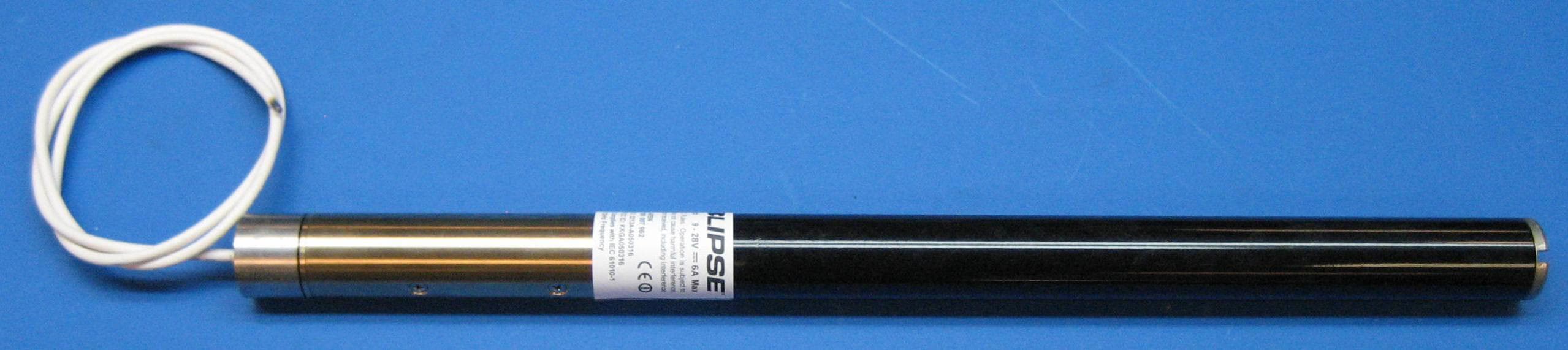
KKGA050316
Apr 03, 2011ECP, FC
Equipment Class
DCD - Part 15 Low Power Transmitter Below 1705 kHz
KKGA191920
Apr 03, 2011SST, SST5
Equipment Class
DCD - Part 15 Low Power Transmitter Below 1705 kHz