KKI-F-3098Bluetooth Module
ShenZhen XinZhongXin Technology Co., Ltd.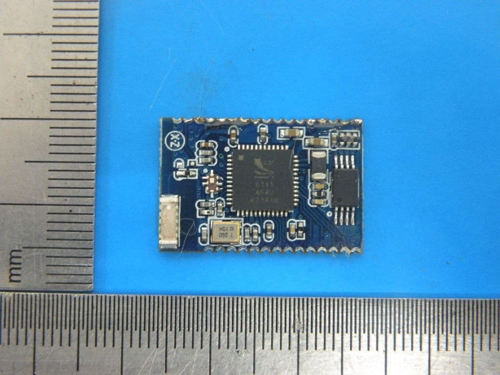
Click to zoom
Application Details
- Equipment Class
- DSS - Part 15 Spread Spectrum Transmitter
- Date of Grant
- Dec 13, 2012
- Application Purpose
- Original Equipment
- Date of Application
- Dec 13, 2012
- Equipment Note
- Bluetooth Module
- Frequency Range
- 2402.00000000 - 2480.00000000
- Country
- China
Documents & Files
Document Text
Text extracted from the exhibit documents filed with the FCC. Open a document above to read the original.
Users Manual
F-3098 use manual Module Description: 1 Significantly enhance the overall the latest CSR BC6 chip, sound quality and RF performance. 2 Accord Bluetooth V3.0 3 Bluetooth headsets, audio, car low cost solution. 4 High-quality audio processing A2DP V1.2. 5 The highest the 2db emission power, -91db accept sensitivity. 6 module size: L23.5*W15.5*H1.8mm. Application: 1 High sound quality Bluetooth headset. 2 Hands free, Bluetooth Car 3 High-quality Bluetooth audio Pin Configurations: Item Name Type Function 1 GND2 GND Ground connections 2 AIO1 Bidirectional Programmable input/output line 3 AIO0 Bidirectional Programmable input/output line 4 PIO20/RX Bidirectional with weak internal pull-down UART data input, active high. PIO[20] is clock for SPI flash interface 5 PIO23 Bidirectional with weak internal pull-up UART data output, active high. PIO[23] is data output for SPI flash interface 6 PIO3 Bidirectional with Programmable input/output line PIO[3] is programmable strength internal pull-up/down chip select for SPI flash interface 7 PIO2 Bidirectional with programmable strength internal pull-up/down Programmable input/output line 8 PIO1 Bidirectional with programmable strength internal pull-up/down Programmable input/output line 9 PIO0 Bidirectional with programmable strength internal pull-up/down Programmable input/output line 10 RST Input with weak internal pull-up Reset if low. Input debounced so must be low for >5ms to cause a reset 11 PIO11 Bidirectional with programmable strength internal pull-up/down Programmable input/output line. PIO[11] is data input for SPI flash interface 12 LED1 Open drain output LED driver 13 LED0 Open drain output LED driver 14 GND3 GND Ground connections 15 GND GND Ground connections 16 1V8 Power Positive supply for blue core 17 POWER_EN / Take high to enable both high-voltage regulator and switch-mode regulator 18 BAT / Lithium ion/polymer battery positive teminal. Battery charger output and input to switch-mode regulator 19 CHG / Lithium ion/polymer battery charger input 20 MIC_BIAS Analogue Microphone bias 21 MIC_P Analogue Microphone input, positive 22 MIC_N Analogue Microphone input, negative 23 SPKP_N Analogue Speaker output, negative 24 SPKP_P Analogue Speaker output, positive 25 MOSI with weak internal pull-down SPI data input 26 CLK Bidirectional with weak internal pull-down SPI clock 27 CSB Bidirectional with weak internal pull-down Chip select for SPI, active low 28 MIS0 Bidirectional with weak internal pull-down SPI data output 29 GND1 GND Ground connections 30 RF RF RF 31 GND0 GND GND Restrictions: Integration limited to Battery-operated host devices. Changes or modifications not expressly approved by the party responsible for compliance could void the user's authority to operate the equipment。 NOTE: This equipment has been tested and found to comply with the limits for a Class B digital device, pursuant to Part 15 of the FCC Rules. These limits are designed to provide reasonable protection against harmful interference in a residential installation. This equipment generates uses and can radiate radio frequency energy and, if not installed and used in accordance with the instructions, may cause harmful interference to radio communications. However, there is no guarantee that interference will not occur in a particular installation. If this equipment does cause harmful interference to radio or television reception, which can be determined by turning the equipment off and on, the user is encouraged to try to correct the interference by one or more of the following measures: -- Reorient or relocate the receiving antenna. -- Increase the separation between the equipment and receiver. -- Connect the equipment into an outlet on a circuit different from that to which the receiver is connected. -- Consult the dealer or an experienced radio/TV technician for help. FCC ID: KKI-F-3098 This device complies with Part 15 of the FCC Rules. Operation is subject to the following two conditions: (1) this device may not cause harmful interference, and (2) this device must accept any interference received, including interference that may cause undesired operation. Important compliance information for North American users The F-3098 Module has been granted modular approval for portable applications. Integrators may use the F-3098 Module in their final products without additional FCC certification if they meet the following conditions. Otherwise, additional FCC approvals must be obtained. 1. To comply with FCC regulations limiting both maximum RF output power and human exposure to RF radiation, the maximum antenna gain including cable loss in a mobile-only exposure condition must not exceed 0dBi in the 2.4G band. 2. The F-3098 Module and its antenna must not be co-located or operating in conjunction with any other transmitter or antenna within a host device. 3. A label must be affixed to the outside of the end product into which the F-3098 Module is incorporated, with a statement similar to the following: For F-3098: This device contains FCC ID: KKI-F-3098. 4. A user m anual with the end product must clearly indicate the operating requirements and conditions that must be observed to ensure compliance with current FCC RF exposure guidelines. The end product with an embedded -F-3098 Module may also need to pass the FCC Part 15 unintentional emission testing requirements and be properly authorized per FCC Part 15.
Cover Letter(s)
Shenzhen Xinzhongxin Technology Co., Ltd. PHOENIX TEST-LAB GmbH Product Certification Königswinkel 10 D 32825 Blomberg Date: 25.10.2012 Authority to Act as an Agent We declare that the following representative (agent) Name Mark Zhu Position Manager Company Name Shenzhen Certification Technology Service Co., Ltd. Address 2F, Building B, East Area of Nanchang Second Industrial Zone, Gushu 2 nd Road, Bao’an District, Shenzhen 518126, P.R. China Tel / Fax 0755-86375541/0755-26736857 Email [email protected] to act on our behalf on all matters concerning the application and documents submitted to PHOENIX TEST-LAB for product certification below Product Name Bluetooth Module Model Name F-3098 Brand Name N/A We also authorize BZT – TCP Certification GmbH, Ms.Wanida Patthanavoj (address: Hermann - Loens - Weg 6, 15859 Storkow b. Berlin Germany) to process the application. Yours sincerely, Signatory Name Lin Lu Position General Manager Company Name Shenzhen Xinzhongxin Technology Co., Ltd. Address 5 Floor, C Bldg., Zhuangbian Industrial Park, Gushu, Baoan District, Shenzhen, China Tel +86-755-29179480 Fax +86-755-84736169 Email [email protected] In case of FCC, we certify that we are not subject to a denial of Federal benefits, that include FCC benefits, pursuant to Section 5301 of the Anti-Drug Abuse Act of 1988, 21 U.S.C. §862 because of a conviction for possession or distribution of a controlled substance.
Cover Letter(s)
Shenzhen Xinzhongxin Technology Co., Ltd. Federal Communications Commission Equipment Authorization Branch 7435 Oakland Mills Road Columbia, MD 21046 Request for Confidentiality Company name: Shenzhen Xinzhongxin Technology Co., Ltd. FCC ID : KKI-F-3098 FCC Part 15 Certification Gentlemen, Pursuant to 47 CFR 0.457(d)(1)(ii) and 0.459 we hereby requests permanent confidentiality of the following documents for the subject application: Exhibit Type Description ☒ Schematics All circuitry of devices and component values ☒ Block Diagrams Details of device showing the frequency of all oscillators ☒ Operational Description Description of the circuit functions Note: Exhibit types that are commonly held confidential are: (1) Schematics, (2) Block Diagrams, (3) Bill Of Materials, (4) Operational Descriptions. Any exhibit NOT granted confidentiality is viewable on the FCC website as soon as a grant is issued. These documents contain detailed system and equipment description and related information about the product which we considers to be proprietary, confidential and a custom design and otherwise would not release to the general public. Since the design is a basis from which future technological products will evolve, we consider that this information would be of benefit to its competitors and that the disclosure of the information in these documents would give competitors an unfair advantage in the market. Yours sincerely, Signatory Name Lin Lu Position General Manager Company Name Shenzhen Xinzhongxin Technology Co., Ltd. Address 5 Floor, C Bldg., Zhuangbian Industrial Park, Gushu, Baoan District, Shenzhen, China Tel +86-755-29179480 Fax +86-755-84736169 Email [email protected]
Cover Letter(s)
FCC Modular Approval Request To the FCC or FCC TCB handling this application Hereby we, Company (grantee) Shenzhen Xinzhongxin Technology Co., Ltd. Addresss 5 Floor, C Bldg., Zhuangbian Industrial Park, Gushu, Baoan District, Shenzhen, China City / ZIP / State / Country Shenzhen/China request modular approval for the certification of our equipment within this application, identified by: FCC ID: KKI-F-3098 The table below contains justification for modular approval of this equipment. Requirement per DA 00-1407 Explanation from grantee 1. The modular transmitter must have its own RF shielding. Not complied, but subject to limited modular approval. Transmitter see the test report STE120926331. 2. The modular transmitter must have buffered modulation/data inputs (if such inputs are provided) to ensure that the module will comply with Part 15 requirements under conditions of excessive data rates or over-modulation. The modular have buffered modulation/data inputs.(BC6145) 3. The modular transmitter must have its own power supply regulation. The modular transmitter have its own power supply regulation.(DC 3.7V, BC6145 internal LDO regulator) 4. The modular transmitter must comply with the antenna requirements of Section 15.203 and 15.204(c). The antenna must either be permanently attached or employ a “unique” antenna coupler (at all connections between the module and the antenna, including the cable).. The modular is comply with the antenna, a white Ceramic antenna. 5. The modular transmitter must be tested in a stand-alone configuration, i.e., the module must not be inside another device during testing. This is intended to demonstrate that the mo d ule is capable of complying with Part 15 emission limits regardless of the device into which it is eventually installed. The modular was tested in a stand-alone configuration. 6. The modular transmitter must be labeled with its own FCC ID number, and, if the FCC ID is not visible when the module is installed inside another device, then the outside of the de v ice into which the module is installed must also display a label referring to the enclosed module. This exterior label can use wording such as the following: “Contains Transmitter Module FCC ID: XYZMODEL1” or “Contains FCC ID: XYZMODEL1.” Any similar wording that expresses the same meaning may be used. The Grantee may either provide such a label, an example of which must be included in the application for equipment authorization, or, must provide adequate instructions along with the module which explain this requirement. In the latter case, a copy of these instructions must be included in the application for equipment authorization. The modular was labelled with its own FCC ID. 7. The modular transmitter must comply with any specific rule or operating requirements applicable to the transmitter a nd the manufacturer must provide adequate instructions along with the module to explain any such requirements. A copy of these instructions must be included in the application for equipment authorization. For example, there are very strict operational and timing requirements that must be met before a transmitter is authorized for operation under Section 15.231. For instance, data transmission is prohibited, except for operation under Section 15.231(e), in which case there are separate field strength level and timing requirements. Compliance with these requirements must be assured. Not complied. The integration is limited to battery powered host devcies. 8. The modular transmitter must comply with any applicable RF exposure requirements. For example, FCC Rules in Sections 2.1091, 2.1093 and specific Sections of Part 15, including 15 . 319(i), 15.407(f), 15.253(f) and 15.255(g), require that Unlicensed PCS, UNII and millimetre wave devices perform routine environmental evaluation for RF Exposure to demonstrate compliance. In addition, spread spectrum transmitters operating under Section 15.247 are required to address RF Exposure compliance in accordance with Section 15.247(b)(4). Modular transmitters approved under other Sections of Part 15, when necessary, may also need to address certain RF Exposure concerns, typically by providing specific installation and operating instructions for users, installers and other interested parties to ensure compliance. The modular is exempted due to it's low field strength. Attestation (by grantee) City and Country: Date: Name: (this must be a person) Function: Signature: (or official company stamp) Shenzhen/China 2012.10.24 Lin Lu General Manager
ID Label/Location Info
Label location FCC ID: KKI-F-3098
Internal Photos
ANTENNA
Test Report
Shenzhen Certification Technology Service Co., Ltd. 2F, Building B, East Area of Nanchang Second Industrial Zone, Gushu 2 nd Road, Bao'an District, Shenzhen 518126, P.R. China FCC ID: KKI-F-3098 Page 1 of 53 TEST REPORT FCC ID: KKI-F-3098 Applicant : Shenzhen Xinzhongxin Technology Co., Ltd. Address : 5 Floor, C Bldg., Zhuangbian Industrial Park, Gushu, Baoan District, Shenzhen, China Equipment Under Test (EUT): Name : Bluetooth Module Model : F-3098 In Accordance with: FCC PART 15.247:2011 Report No : STE120926331 Date of Test : October 10-16, 2012 Date of Issue : October 17, 2012 Test Result: PASS In the configuration tested, the EUT complied with the standards specified above Authorized Signature ___________________________ (Mark Zhu) General Manager The manufacture should ensure that all the products in series production are in conformity with the product sample detailed in this report. If the product in this report is used in any configuration other than that detailed in the report, the manufacturer must ensure the new system complies with all relevant standards. Any mention of Shenzhen Certification Technology Service Co., Ltd. Or test done by Shenzhen Certification Technology Service Co., Ltd. Approvals in connection with, distribution or use of the product described in this report must be approved by Shenzhen Certification Technology Service Co., Ltd. Approvals in writing. Report No.: STE120926331 FCC ID: KKI-F-3098 Page 2 of 53 Contents 1. General Information...............................................................................................................4 1.1. Description of Device (EUT)..........................................................................................4 1.2. Accessories of device (EUT)..........................................................................................4 1.3. Test Lab information.......................................................................................................4 2. Summary of test......................................................................................................................5 2.1. Summary of test result....................................................................................................5 2.2. Assistant equipment used for test...................................................................................5 2.3. Block Diagram................................................................................................................6 2.4. Test mode........................................................................................................................6 2.5. Test Conditions...............................................................................................................6 2.6. Measurement Uncertainty (95% confidence levels, k=2)...............................................7 2.7. Test Equipment...............................................................................................................8 3. Maximum Peak Output power..............................................................................................9 3.1. Test limit.........................................................................................................................9 3.2. Test Procedure.................................................................................................................9 3.3. Test Setup........................................................................................................................9 3.4. Test Results.....................................................................................................................9 4. 20dB bandwidth....................................................................................................................10 4.1. Limit.............................................................................................................................10 4.2. Test Procedure...............................................................................................................10 4.3. Test Result.....................................................................................................................10 5. Carrier Frequency Separation............................................................................................14 5.1. Limit.............................................................................................................................14 5.2. Test Procedure...............................................................................................................14 5.3. Test Result.....................................................................................................................14 6. Number Of Hopping Channel.............................................................................................16 6.1. Limit.............................................................................................................................16 6.2. Test Procedure...............................................................................................................16 6.3. Test Result.....................................................................................................................16 7. Dwell Time.............................................................................................................................19 7.1. Test limit.......................................................................................................................19 7.2. Test Procedure..............................................................................................................19 7.3. Test Results...................................................................................................................19 8. Radiated emissions................................................................................................................30 8.1. Limit.....................…
Text truncated - open the document above for the full version.
Test Setup Photos
Photos of Radiated emission
Contact Information
Applicant
Lin Lu(General Manager)
Test Firm
Shenzhen Certification Technology Service Co., LtdMark Zhu
Technical Specifications
| # | Rule Parts | Frequency Range | Power Output |
|---|---|---|---|
| 1 | 15C | 2.40 GHz - 2.48 GHz | 1.00 mW |
Other Applications from ShenZhen XinZhongXin Technology Co., Ltd.
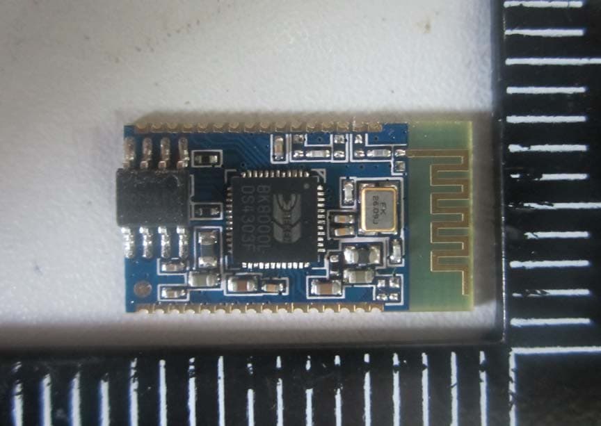
KKI-F-6188
Oct 26, 2014Bluetooth Module
Equipment Class
DSS - Part 15 Spread Spectrum Transmitter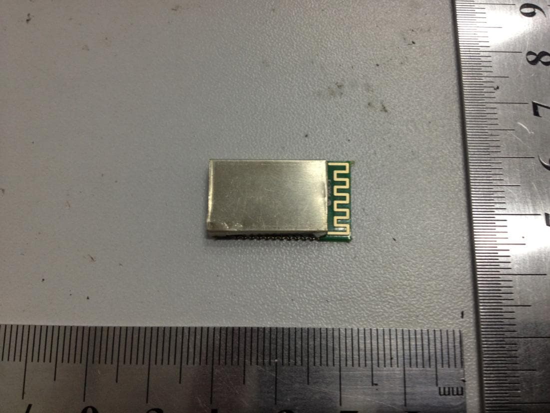
KKI-F-3056
Aug 18, 2013Bluetooth Module
Equipment Class
DSS - Part 15 Spread Spectrum Transmitter
KKI-F-6088
Aug 08, 2013Bluetooth module
Equipment Class
DSS - Part 15 Spread Spectrum Transmitter
KKI-F-3086
Apr 11, 2013Bluetooth Module
Equipment Class
DSS - Part 15 Spread Spectrum Transmitter
KKI-F-3088
Jun 11, 2012Bluetooth Module
Equipment Class
DSS - Part 15 Spread Spectrum Transmitter