KL7-412-V1Active RFID Tag
Savi Technology Inc
Click to zoom
Application Details
- Equipment Class
- DSR - Part 15 Remote Control/Security Device Transceiver
- Date of Grant
- Oct 02, 2000
- Application Purpose
- Original Equipment
- Date of Application
- Aug 23, 2000
- Equipment Note
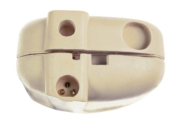
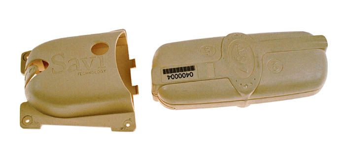
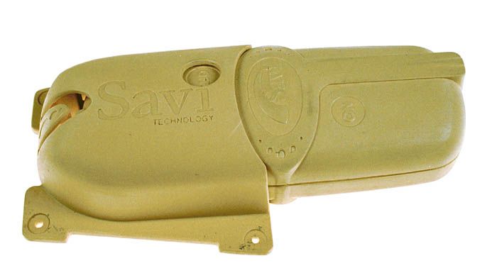
- Active RFID Tag
- Frequency Range
- 433.95500000 - 433.95500000
- Company
- Savi Technology Inc
- Country
- United States
Documents & Files
Document Text
Text extracted from the exhibit documents filed with the FCC. Open a document above to read the original.
Users Manual
Mounting the ST-412 Tag with the MB-412 Mounting Bracket Tools and Materials • Marking pencil • Drill with #30 (.129) bit • Three rivets (provided with mounting bracket) • Hand-held rivet gun (recommended vendor: Pencom (distributor) PH: 1-650-573-1297 Marson P/N AB4- 4CLD or Creative P/N BAS44-CE) • One 3.6V lithium battery, size AA (provided with tag) Savi Technology recommends using supplied rivets and recommended gun to install tag mounting bracket. Customers use other installation methods at their own risk. The tag mounting bracket is 5.01 inches long, 3.1 inches wide, and 1.69 inches high. The tag is 6.8 inches long, 2.8 inches wide, and 1.52 inches high. 1. Identify tag location: a flat, vertical space that can have a tag mounting bracket riveted to it. Place tags high for good radio communication and where they are safe from impact (e.g. inside the ribs of a container). Place tags vertically (labels upright), as shown below. On shipping containers, Savi recommends placing tags on the container side approximately 1 foot from the top corner of the container. 2. Drill three holes using the tag mounting bracket as a template to mark holes. 3. Push rivets through tag mounting bracket and mounting surface. 4. Use hand-held rivet gun to secure tag to mounting surface. It could take up to 3 squeezes of the gun to successfully secure a rivet and sheer off excess pin. 1. Make sure the 3.6V lithium battery is installed properly in the tag (see other side). 2 Slide tag into mounting bracket (labels right-side up) until it locks in place. 3To enable tab, ensure that the On Designation can be seen through the window on the mounting bracket. If successful, the tag should beep twice after inserted into the bracket. When removed from the bracket, the tag will beep once before shutting off. 4 To disable tag, ensure that the Off Designation can be seen through the window on the mounting bracket. If successful, the tag should not beep after being inserted into the bracket.Replacing the Battery Tools and Materials • Replacement 3.6V lithium battery, size AA 1. Remove the battery cover: push firmly against the grooved thumb plate to release the catch and slide the cover slowly down as shown. When removing the battery cover, hold it as it comes loose to prevent dropping it. 2. Remove the discharged battery from its compartment. The lithium battery can be harmful to the environment. Please follow current procedures for safely disposing of lithium batteries. Copyright ©1999, Savi Technology Incorporated. All rights reserved. First edition printed September 1997. Copyright protection claimed includes all forms and matters of copyrightable material and information, now allowed by statutory or judicial law or hereinafter granted. Information in this guide is subject to change without notice and does not represent a commitment from the vendor. 3. Install AA 3.6V lithium battery, matching the negative (–) and positive (+) terminals to the symbols shown in the battery compartment. 2. Replace the battery cover by sliding it into place until it fits flush with the tag case. Listen for the click as it seats. Make sure that the battery cover is completely closed. You may need to open the rubber plug covering the docking port, close the battery cover, and then close the rubber plug again. 2. Dispose of used battery according to local safety requirements. The tag does not work if you install the battery in the wrong direction (reversed). Savi order number xxxxxxxxx Savi part number xxxxxxxxxx Savi is a registered trademark and SaviTag is a trademark of Savi Technology Incorporated. Other product names mentioned in this guide may be trademarks or registered trademarks of their respective owners and are hereby acknowledged. Problems? After you have tested that the SaviTag battery is working, and checked the Savi System Installation Guide, telephone Savi Technical Support at 1-888- 994-SAVI (1-888-994-7284), between 9:30 a.m. and 5 p.m. Pacific Time
Users Manual
1 SaviTag 410 Federal Communications Commission (FCC) Notice The Federal Communications Commission has established technical standards regarding radio frequency energy emitted by computer devices. This equipment has been tested and found to comply with the limits for a Class B digital device, pursuant to Part 15 of the FCC Rules. These limits are designed to provide reasonable protection against harmful interference in a residential installation. This equipment generates, uses, and can radiate radio frequency energy and, if not installed and used in accordance with the instructions, may cause harmful interference with radio/TV reception. However, there is no guarantee that interference will not occur in a particular installation. If this equipment does cause harmful interference to radio or television reception, which can be determined by turning the equipment off and on, the user is encouraged to try and correct the interference by one or more of the following measures: • Reorient or relocate the receiving antenna. • Increase the separation between the equipment and receiver. • Connect the equipment into an outlet on a circuit different from that to which the receiver is connected. • Consult the dealer or an experienced radio/TV technician for help. Warning: Changes or modifications to this equipment that are not expressly approved by Savi Technology could void the warranty and the authority to operate this equipment. Savi Technology is not responsible for radio/TV interference caused by using unauthorized cable or by making unauthorized changes to this equipment. Federal Communications Commission (FCC) Label Statement This device complies with Part 15 of the FCC Rules. Operation is subject to the following conditions: • This device may not cause harmful interference, and • This device must accept any interference received, including interference that may cause undesired operation. The label statement corresponds to the following devices: Device Model FCC ID Radio tag ST-412-001 KL7-412-V1 Savi Technology 615 Tasman Drive Sunnyvale, CA 94089-1707 Phone: (408) 743-8000 Fax: (408) 543-8650 E-mail: [email protected] Web site: www.savi.com Savi Document Part Number: xxxxxxxxxxxxx Copyright © 2000, Savi Technology Incorporated. All rights reserved. Copyright protection claimed includes all forms and matters of copyrightable material and information, now allowed by statutory or judicial law or hereinafter granted. Information in this guide is subject to change without notice and does not represent a commitment from the vendor. Savi is a registered trademark and SaviTag is a trademark of Savi Technology Incorporated. Other product names mentioned in this guide may be trademarks or registered trademarks of their respective owners and are hereby acknowledged.
Cover Letter(s)
File: R38960 August 17, 2000 Chief, Equipment Authorization Branch, Authorization and Evaluation Division, Office of Engineering and Technology FEDERAL COMMUNICATIONS COMMISSION P.O. Box 358315 Pittsburgh, PA 15251-5315 Gentlemen: The enclosed documents constitute a formal submittal and application for a Grant of Equipment Authorization pursuant to Subpart C of Part 15 of FCC Rules (CFR 47) regarding intentional radiators. Data within this report demonstrates that the equipment tested complies with the FCC limits for intentional radiators. Elliott Laboratories, as duly authorized agent prepared this submittal. A copy of the letter of our appointment as agent is enclosed. If there are any questions or if further information is needed, please contact Elliott Laboratories for assistance. Sincerely, Mark R. Briggs Manager, EMC Consulting Services MRB/dmg Enclosures: Agent Authorization Letter Emissions Test Report with Exhibits
Operational Description
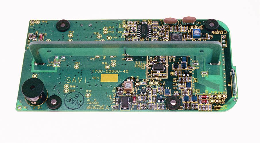
Functional Description Of SaviTag 412, Model ST-412-XXX 1. Power Supply The power supply consists of a single 3.6 volt AA lithium battery. 2. 433 MHz Receiver, Wide Area Communication The receiver consists of a single transistor RF amplifier followed by a mixer/IF detector. A SAW controlled local oscillator operates at 423.22 MHz to down convert the incoming signal to a 10.7 MHz IF frequency. This receiver processes control and data commands from a reader. 3. 433 MHz Transmitter The transmitter converts digital data from the microcontroller into a 433.92 MHz FSK signal which is then transmitted via the antenna to the reader (interrogator). The transmitter consists of a SAW controlled oscillator, single transistor buffer stage and a discrete component output filter. 4. CPU A Philips 87C51RD with a clock frequency of 8 MHz. The 8 MHz is divided by 6 to generate a 1.33 MHz Address Latch Enable for the EPROM. 5. EEPROM 4Kbyte serial EEPROM (nonvolatile) for the tag ID configuration data and user data. 6. Beeper It is self-contained and is controlled directly by the microcontroller which provides operating power at 3.0 to 3.6 volts. The beeper will emit two beeps when the tag powers up. The beeper will emit one beep when the tag powers down. 7. Reed Switch The Reed Switch is closed when placed in proximity of a magnet. The mounting bracket for this tag has a magnet such that the Reed Switch closes only when the Tag is inserted into its bracket. Closing the Reed Switch provides power to the tag.
Test Report
File: R38960 Page 1 of 14 Electromagnetic Emissions Test Report and Application for Grant of Equipment Authorization pursuant to FCC Part 15, Subpart C Specifications for an Intentional Radiator on the Savi Technology, Inc. Model: SaviTag 412 FCC ID: KL7-412-V1 GRANTEE: Savi Technology, Inc. 615 Tasman Drive Sunnyvale, CA. 94089-1707 TEST SITE: Elliott Laboratories, Inc. 684 W. Maude Avenue Sunnyvale, CA 94086 REPORT DATE: August 17, 2000 FINAL TEST DATE: August 8, 2000 AUTHORIZED SIGNATORY: ______________________________ Mark R. Briggs Manager, EMC Consulting Services This report shall not be reproduced, except in its entirety, without the written approval of Elliott Laboratories, Inc. Elliott Laboratories, Inc. -- EMC Department Test Report Report Date: August 17, 2000 File: R38960 Page 2 of 14 pages TABLE OF CONTENTS COVER PAGE..................................................................................................................................................................................1 TABLE OF CONTENTS...............................................................................................................................................................2 SCOPE.............................................................................................................................................................................................4 OBJECTIVE...................................................................................................................................................................................4 STATEMENT OF COMPLIANCE..............................................................................................................................................4 EMISSION TEST RESULTS.......................................................................................................................................................5 LIMITS OF CONDUCTED INTERFERENCE VOLTAGE....................................................................................................5 LIMITS OF RADIATED INTERFERENCE FIELD STRENGTH – FUNDAMENTAL EMISSIONS.............................5 LIMITS OF RADIATED INTERFERENCE FIELD STRENGTH – SPURIOUS EMISSIONS..........................................5 LIMITS OF BANDWIDTH......................................................................................................................................................5 MEASUREMENT UNCERTAINTIES....................................................................................................................................6 EQUIPMENT UNDER TEST (EUT) DETAILS..........................................................................................................................7 GENERAL...................................................................................................................................................................................7 ENCLOSURE..............................................................................................................................................................................7 MODIFICATIONS....................................................................................................................................................................7 SUPPORT EQUIPMENT..........................................................................................................................................................7 EUT INTERFACE PORTS........................................................................................................................................................7 EUT OPERATION.....................................................................................................................................................................7 TEST SITE......................................................................................................................................................................................8 GENERAL INFORMATION....................................................................................................................................................8 RADIATED EMISSIONS CONSIDERATIONS....................................................................................................................8 MEASUREMENT INSTRUMENTATION..................................................................................................................................9 RECEIVER SYSTEM.................................................................................................................................................................9 INSTRUMENT CONTROL COMPUTER..............................................................................................................................9 LINE IMPEDANCE STABILIZATION NETWORK (LISN)...............................................................................................9 POWER METER......................................................................................................................................................................10 FILTERS/ATTENUATORS...................................................................................................................................................10 ANTENNAS............................................................................................................................................................................10 ANTENNA MAST AND EQUIPMENT TURNTABLE....................................................................................................10 INSTRUMENT CALIBRATION...........................................................................................................................................10 TEST PROCEDURES..............................................................................................................................................................…
Text truncated - open the document above for the full version.
Contact Information
Applicant
Rosemary Johnston(Vice President, Operations)
Technical Contact
Elliott Laboratories, Inc.Mark R Briggs
[email protected]408-245-7800
684 West Maude Ave · Sunnyvale, California · United States
Non-Technical Contact
Elliott LaboratoriesMark R Briggs
[email protected]408-245-7800
Test Firm
Elliott Laboratories LLCDavid Bare
Technical Specifications
| # | Rule Parts | Frequency Range | Power Output | Tolerance |
|---|---|---|---|---|
| 1 | 15C | 433.955 MHz - 433.955 MHz | - | ppm |
Other Applications from Savi Technology Inc

KL7-650MR-V6
Aug 11, 2010RFID Reader
Equipment Class
DSR - Part 15 Remote Control/Security Device Transceiver
KL7-694T-V1
Jun 03, 2010RFID TAG
Equipment Class
DXT - Part 15 Low Power Transceiver, Rx Verified
KL7-696T-V1
Feb 05, 2008RFID Tag
Equipment Class
DXT - Part 15 Low Power Transceiver, Rx Verified
KL7-602T-V1
Aug 02, 2007RFID Tag
Equipment Class
DSR - Part 15 Remote Control/Security Device Transceiver
KL7-662T-V2
May 17, 2007Active RF ID Tag
Equipment Class
DSC - Part 15 Security/Remote Control Transmitter