KLS-82-501
Orolia Ltd
Click to zoom
Application Details
- Equipment Class
- GEP - 406 MHz EPIRB
- Date of Grant
- Dec 19, 2000
- Application Purpose
- Original Equipment
- Date of Application
- Aug 21, 2000
- Frequency Range
- 406.02800000 - 406.02800000
- Company
- Orolia Ltd
- Country
- United Kingdom
Documents & Files

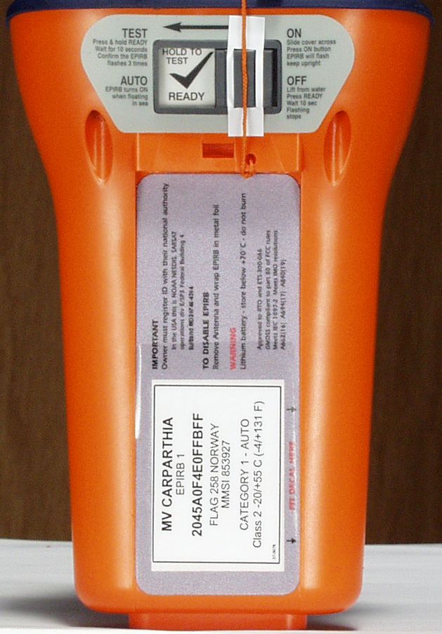
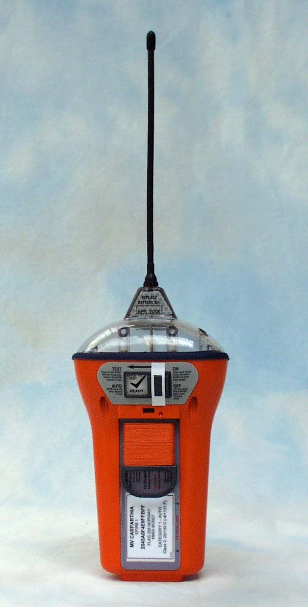
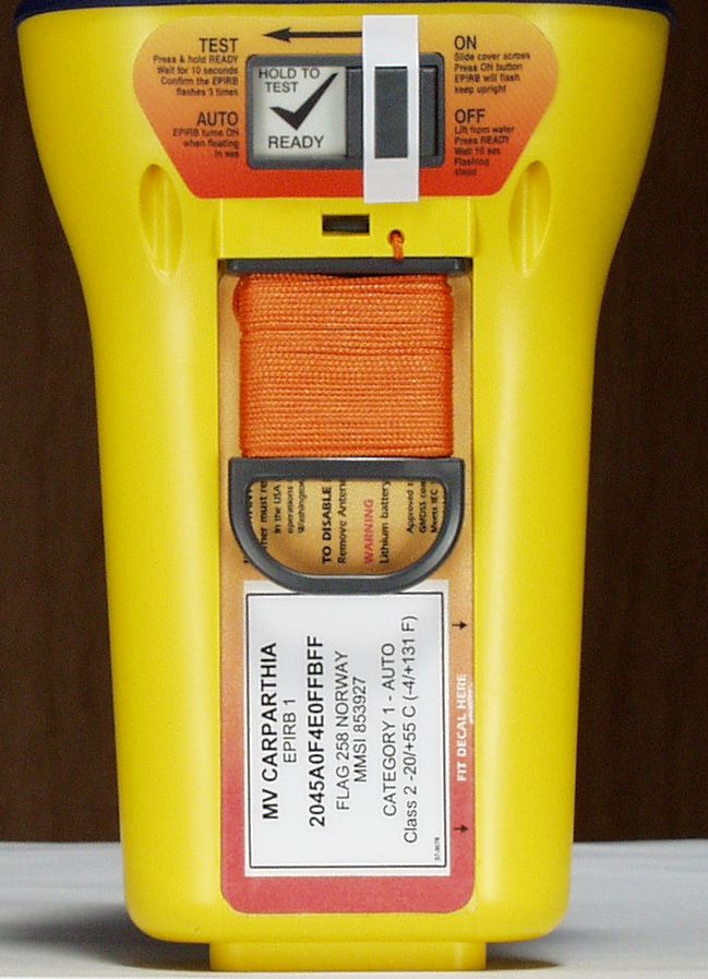
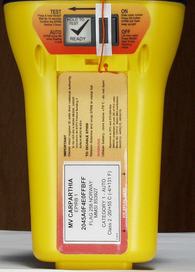
Document Text
Text extracted from the exhibit documents filed with the FCC. Open a document above to read the original.
Users Manual
OWNERS MANUAL VRV 3 4 2 2 1 1 5 1 1Warnings................................................................................................................ 2 2Introduction ........................................................................................................... 3 2.1COSPAS-SARSAT satellite system ...............................................................................3 2.2Global Positioning System (GPS) ..................................................................................4 3Purpose.................................................................................................................. 5 4Description ............................................................................................................ 6 4.1Wall bracket ...................................................................................................................6 4.2Float-free enclosure .......................................................................................................7 4.3Manual G4 in enclosure .................................................................................................8 5Controls ................................................................................................................. 9 5.1ON button ......................................................................................................................9 5.2READY button................................................................................................................9 5.3Sea switch .....................................................................................................................9 5.4Lamps ..........................................................................................................................10 6Operating procedure .......................................................................................... 11 6.1Sinking .........................................................................................................................11 6.2Abandon ship ...............................................................................................................11 6.3Releasing G4 from a wall bracket.................................................................................11 6.4Releasing G4 from an enclosure ..................................................................................12 6.5Manual activation .........................................................................................................12 6.6Deactivation .................................................................................................................13 6.7Battery condition ..........................................................................................................13 6.8Re-fitting G4.................................................................................................................13 7False alarms ........................................................................................................ 15 7.1Stand down rescue services ........................................................................................15 7.2De-activate the EPIRB .................................................................................................15 7.3Dealing with a transmitting G4 .....................................................................................16 8Wall bracket installation..................................................................................... 17 8.1Siting............................................................................................................................17 8.2Mounting procedure .....................................................................................................17 8.3Mounting instruction plate ............................................................................................18 9Enclosure installation......................................................................................... 19 9.1Siting............................................................................................................................19 9.2Mounting procedure .....................................................................................................19 9.3Mounting instruction plate ............................................................................................20 9.4Marking HRU expiry.....................................................................................................20 9.5Marking vessel name ...................................................................................................21 10 Registration ......................................................................................................... 22 10.1Overview ..................................................................................................................22 10.2How to register .........................................................................................................22 10.3Warranty form ..........................................................................................................22 10.4Radio licence ...........................................................................................................23 10.5Sale or transfer ........................................................................................................23 11 Maintenance ........................................................................................................ 24 11.1Monthly self-test & inspection...................................................................................24 11.2HRU replacement.....................................................................................................25 11.3Battery replacement .................................................................................................26 11.4Servicing .....................................…
Text truncated - open the document above for the full version.
Users Manual
OWNERS MANUAL VRV 3 4 2 2 1 1 5 1 1Warnings................................................................................................................ 2 2Introduction ........................................................................................................... 3 2.1COSPAS-SARSAT satellite system ...............................................................................3 2.2Global Positioning System (GPS) ..................................................................................4 3Purpose.................................................................................................................. 5 4Description ............................................................................................................ 6 4.1Wall bracket ...................................................................................................................6 4.2Float-free enclosure .......................................................................................................7 4.3Manual Precision 406 in enclosure.................................................................................8 5Controls ................................................................................................................. 9 5.1ON button ......................................................................................................................9 5.2READY button................................................................................................................9 5.3Sea switch .....................................................................................................................9 5.4Lamps ..........................................................................................................................10 6Operating procedure .......................................................................................... 11 6.1Sinking .........................................................................................................................11 6.2Abandon ship ...............................................................................................................11 6.3Releasing Precision 406 from a wall bracket ................................................................11 6.4Releasing Precision 406 from an enclosure .................................................................12 6.5Manual activation .........................................................................................................12 6.6Deactivation .................................................................................................................13 6.7Battery condition ..........................................................................................................13 6.8Re-fitting Precision 406 ................................................................................................13 7False alarms ........................................................................................................ 15 7.1Stand down rescue services ........................................................................................15 7.2De-activate the EPIRB .................................................................................................15 7.3Dealing with a transmitting Precision 406.....................................................................16 8Wall bracket installation..................................................................................... 17 8.1Siting............................................................................................................................17 8.2Mounting procedure .....................................................................................................17 8.3Mounting instruction plate ............................................................................................18 9Enclosure installation......................................................................................... 19 9.1Siting............................................................................................................................19 9.2Mounting procedure .....................................................................................................19 9.3Mounting instruction plate ............................................................................................20 9.4Marking HRU expiry.....................................................................................................20 9.5Marking vessel name ...................................................................................................21 10 Registration ......................................................................................................... 22 10.1Overview ..................................................................................................................22 10.2How to register .........................................................................................................22 10.3Warranty form ..........................................................................................................22 10.4Radio licence ...........................................................................................................23 10.5Sale or transfer ........................................................................................................23 11 Maintenance ........................................................................................................ 24 11.1Monthly self-test & inspection...................................................................................24 11.2HRU replacement.....................................................................................................25 11.3Battery replacement .................................................................................................26 11.4Servicing .................................................................…
Text truncated - open the document above for the full version.
Attestation Statements
4 th of September 2000 We made an error when we filled in the 731 form. The error is in the emission designation box for the 121 transmitter. We typed 3K20A3N; this should have been 3K20A3X. I trust this can be corrected without re- submission. Richard Read (Senior Engineer) McMurdo Ltd.
Attestation Statements
CFR 47 PART 80.1101(b) ParaREQUIREMENTSTATUS 1IMO RESOLUTION A.694(17)Compliant 2CCIT RECOMMENDATION E.161 Not applicable. No telephone functions. 3CCIT RECOMMENDATION Q.11Not applicable. No telephone functions. 4IEC-PUBLICATION 92-101Not applicable. Not connected to ship supply. 5IEC-PUBLICATION 533Not applicable. Not normally on, emergency use only. 6IEC-PUBLICATION 945Compliant 7ISO STANDARD 3791Not applicable. No numeric keyboard. FCC 47 PART 80.1101(c) 5 ParaREQUIREMENTSTATUS (i)IMO RESOLUTION A.611(15) †Compliant (ii)IMO RESOLUTION A.662(16)Compliant (iii)CCIR RECOMMENDATION 633- 1 Compliant (iv)80.1061Compliant † Superseded by A.763(18)
Attestation Statements
CFR 47 PART 80.1061(b) The method used was as detailed in 2.1515(c). The test was carried out using a Hewlett Packard 8568B spectrum analyser. All settings as per the FCC method. The video bandwidth was set for the maximum of 3MHz. The mean power correction for duty cycle made use of the highest duty cycle as this gave the worst results for carrier power content. Characteristic121.65MHz Total wideband power19.65dBm Highest duty cycle45.4% 10log (Duty) factor-3.43dB Total mean power16.22dBm Carrier power13.4dBm dBc-dBt-3.32 Carrier content52.24% Hence 52.24% of the power is contained within + 30Hz of the nominal centre frequency.
Block Diagram
BLOCK DIAGRAM OF G4 ELECTRONICS BATTERY SWITCH CONTROL LOGIC ON READY SEA SWITCH TEST OUTPUT LED DRIVERS LEDS MICRO- CONTROLLER STROBE CIRCUIT XENON TUBE 121.5MHz OSCILLATOR BUFFERPA MODULATION PHASE MODULATOR OCXOBUFFERPA PHASE LOCKED LOOP VCO PA ON/OFF CONTROL MODULATION DIPLEXER ATU DETECTOR DIVISION RATIO STROBE AND REGULATOR 3V5 MICROCONTROLLE REGULATOR 3V7 ON/OFF VCO/PLL REGULATOR 5V 121.5MHz OSCILLATOR 5V REGULATOR OCXO 406 PA 121 PA ANTENNA REED SWITCH GPS MODULELNA REGULATOR 3V3 ON/OFF GPS MODULE TRANSMIT RECEIVE ANTENNA NMEA DATA OUTPUT
Cover Letter(s)
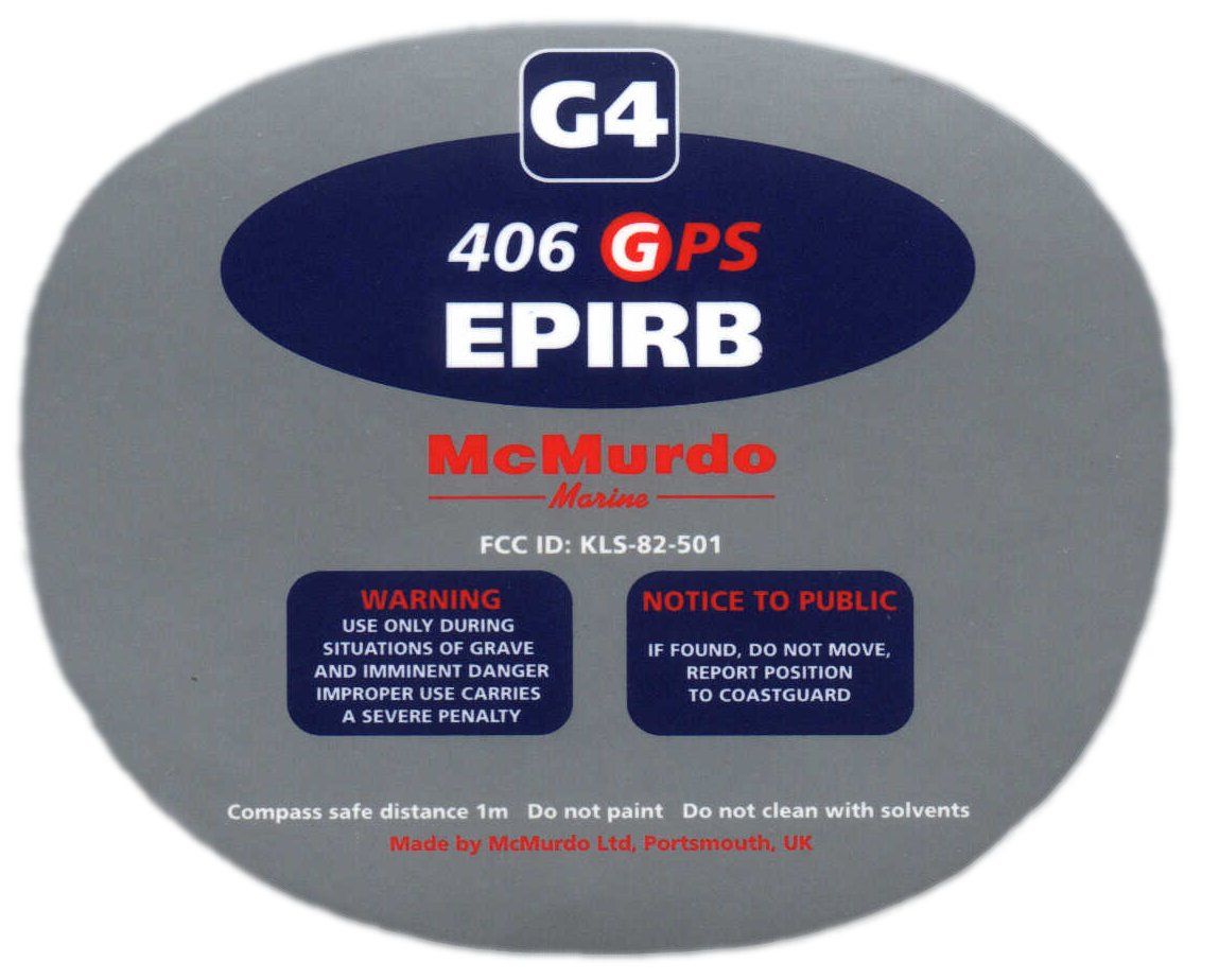
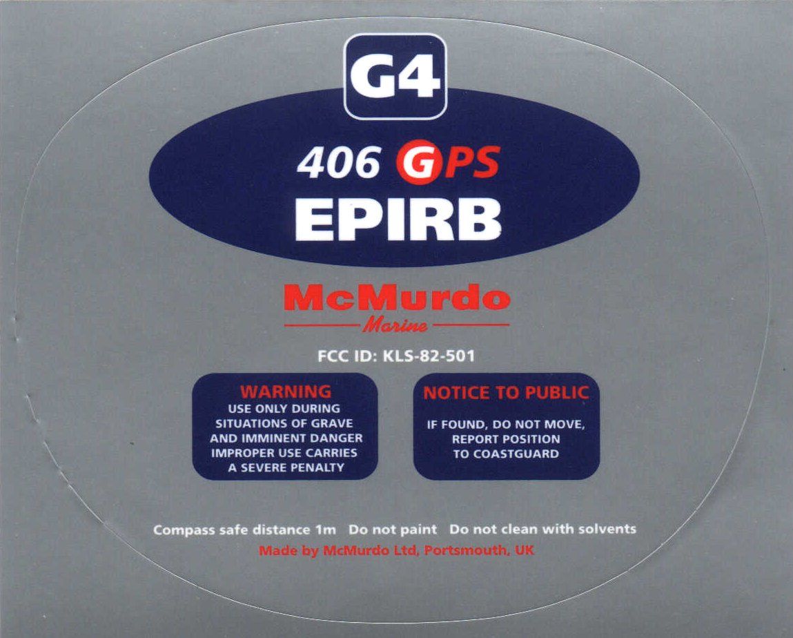
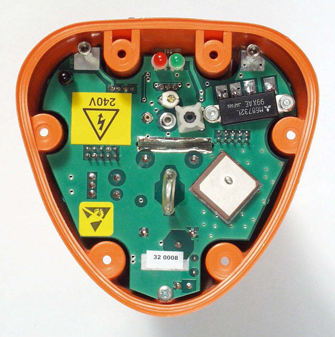
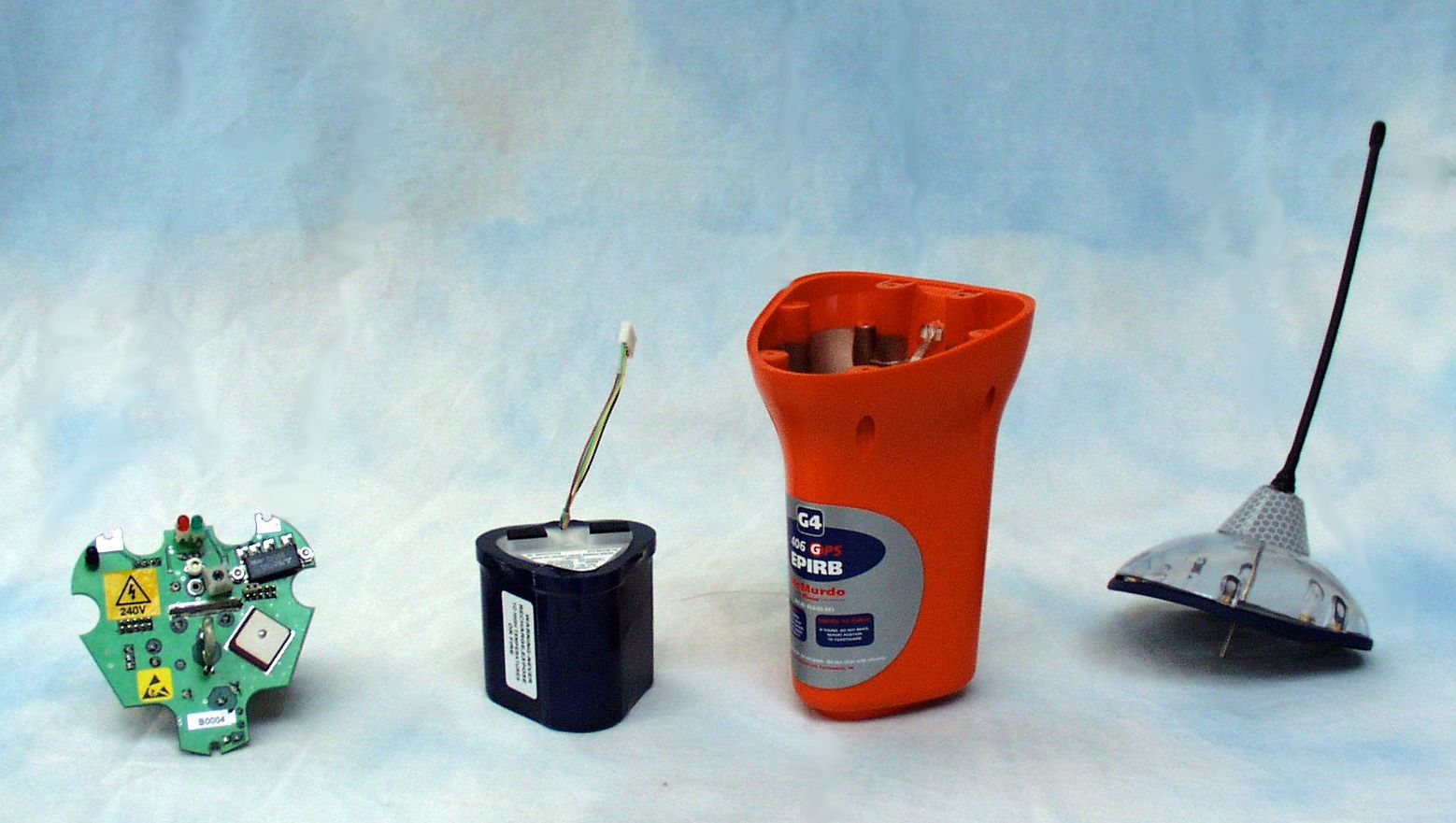
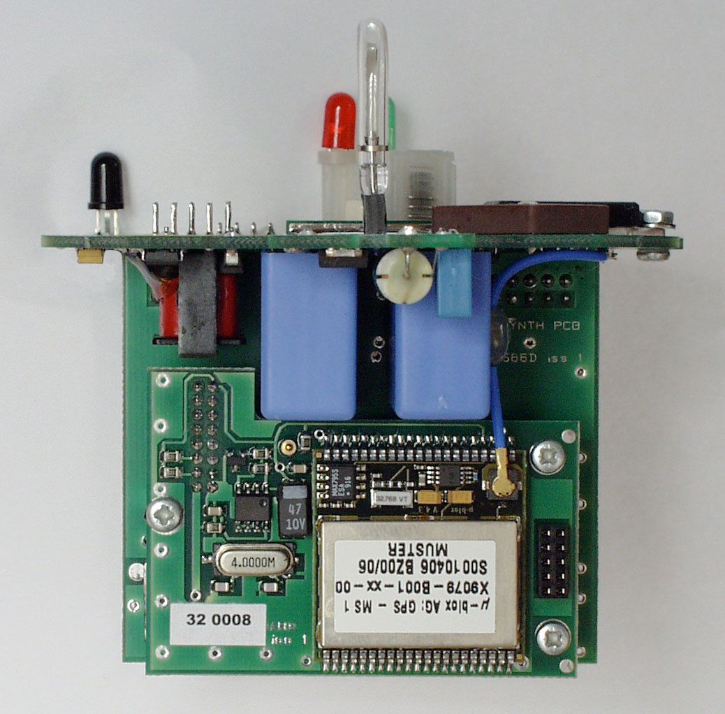
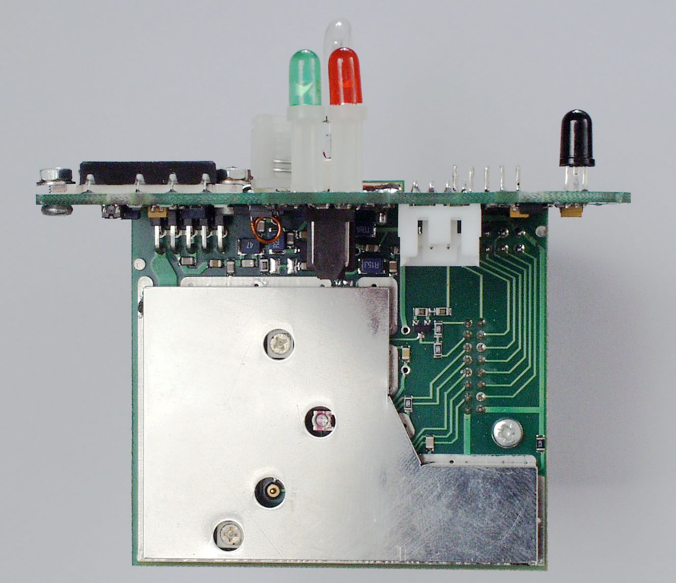
Introductory note for FCC submission (ID : KLS–82-501) This submission contains details of the 'G4' 406MHz GPS EPIRB. This is a new product, based upon the existing E3 EPIRB (FCC ID: KLS-82-001), manufactured by McMurdo Ltd at their Rodney Road facility in Portsmouth, England. This new product utilises the E3 EPIRB mechanics and has the same strobe, 406MHz and 121MHz circuitry. The differences include:- 1) The addition of a daughter board to accommodate the GPS module and its associated interface circuitry. 2) A different microprocessor has been selected to cope with the additional software coding for the Location Protocols. 3) A GPS band patch antenna and associated LNA has been added to the existing strobe board. This is mounted next to the strobe tube and is concealed under the sealin g gasket. 4) A green LED has been mounted next to the existing red LED to provide indication of correct GPS receiver operation 5) Finally in compliance with Cospas-Sarsat requirements the EPIRB transmit frequency has been changed to 406.028 MHz instead of 406.025 MHz. This change of frequency has been discussed with Mr Frank Coperich at the FCC Labs and we understand that agreement has been obtained to allow a waiver for this frequency, pending proposed FCC rule changes under a current NPRM. As the EPIRB mechanics, strobe, 121.5 MHz and 406 MHz circuits are unchanged from the McMurdo E3 EPIRB (FCC ID: KLS-82-001) a reduced set of tests was agreed with the USCG –G-MSE-4 (Commandant R. Markle). An RTCM Test Report and USCG Approval letter are included in this submission. Cospas-Sarsat testing to T-007 was undertaken and a complete Test Report is available if required. A copy of the Cospas-Sarsat Type Approval Certificate is included with this submission. Finally EMC testing has been carried out and copies of the results are again included with this submission. Richard Read (Senior Engineer) E-Mail: [email protected] McMurdo Ltd
Operational Description
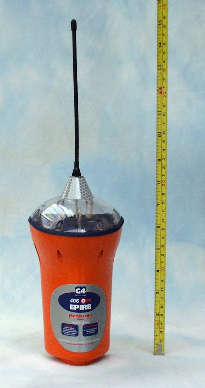
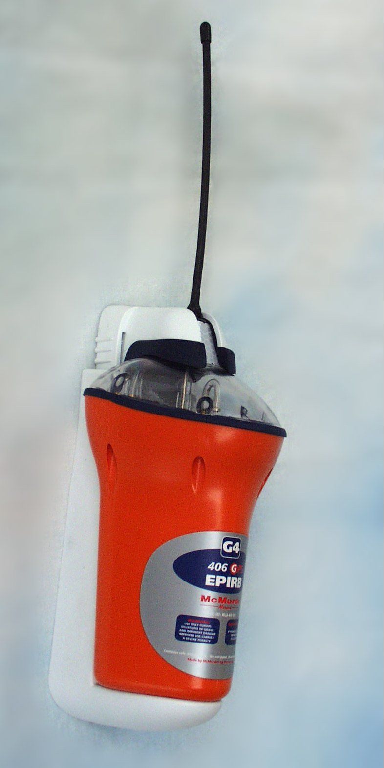
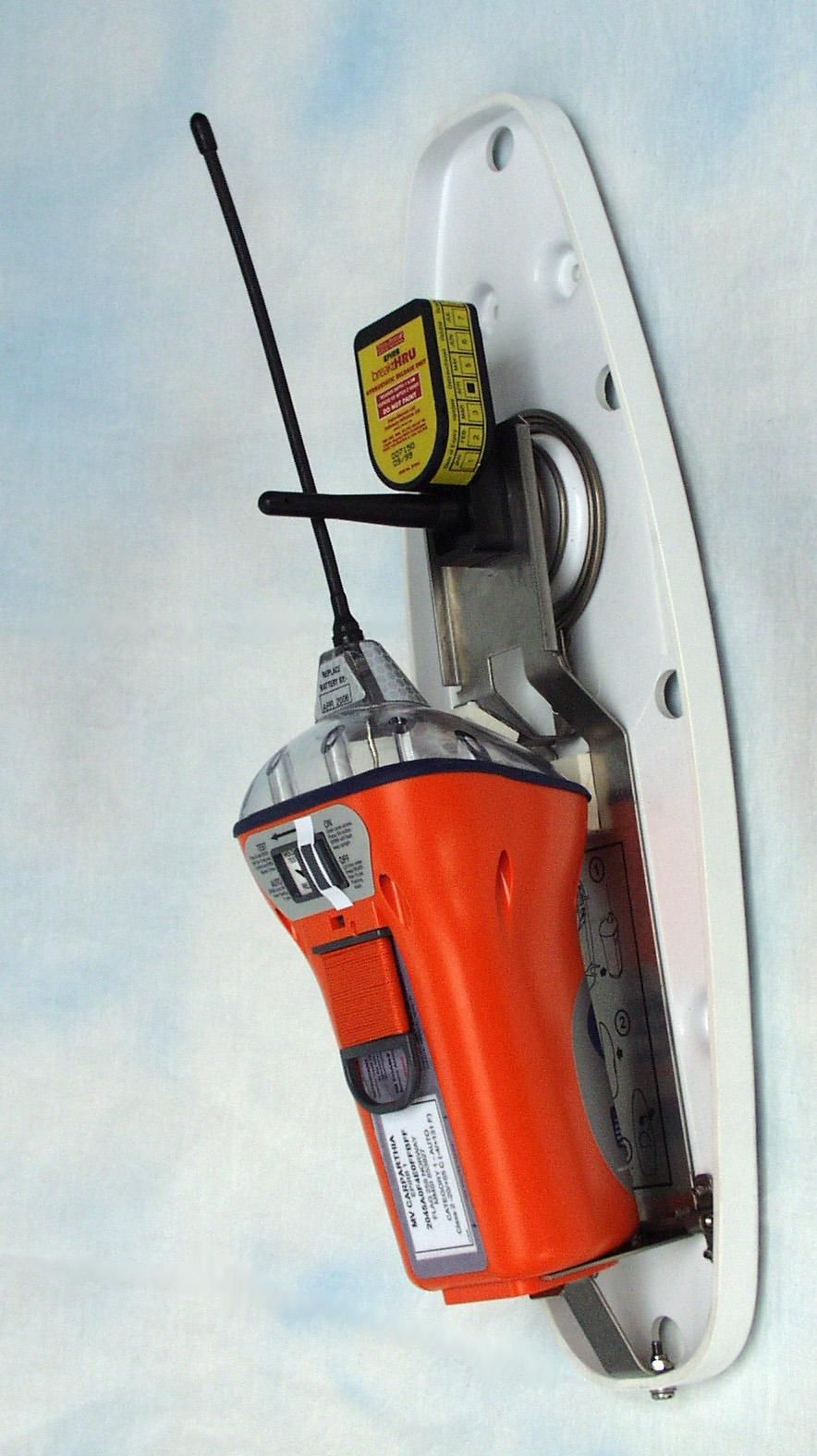
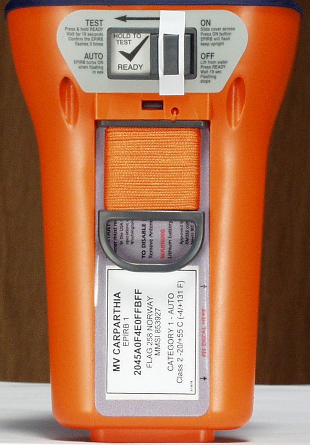
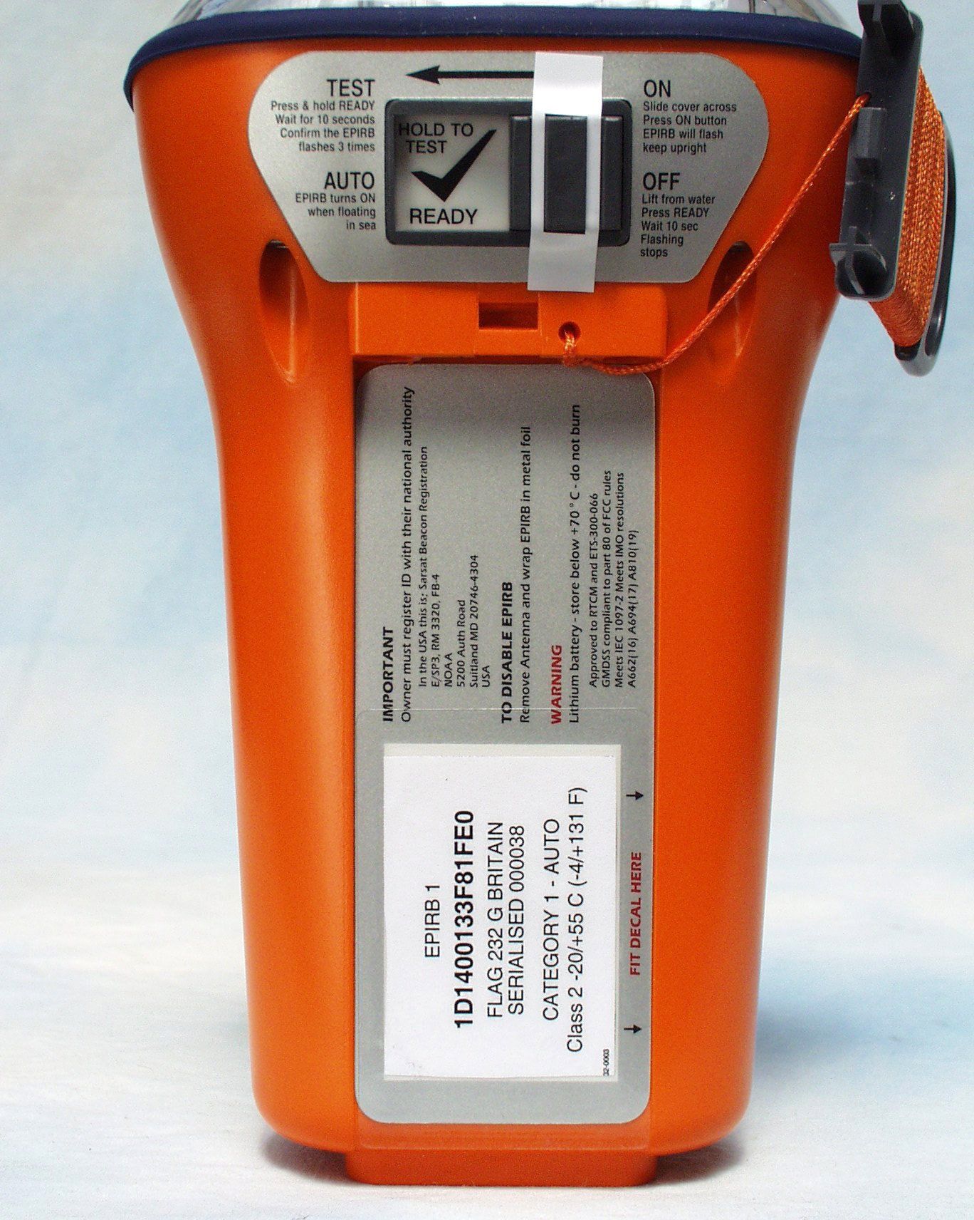
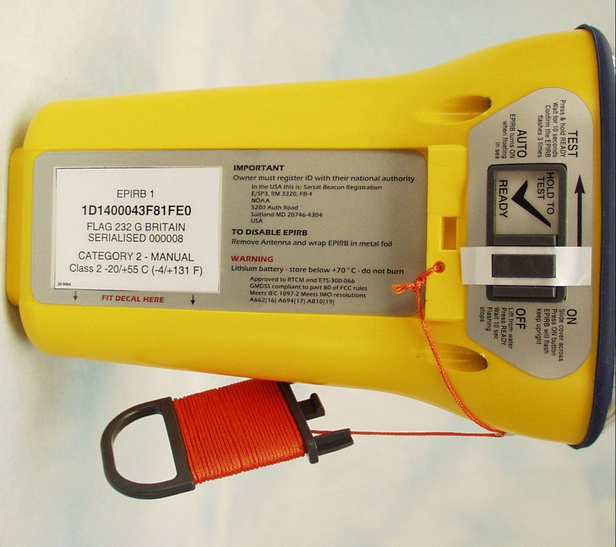
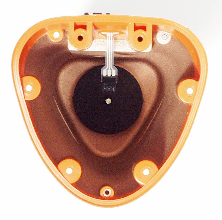
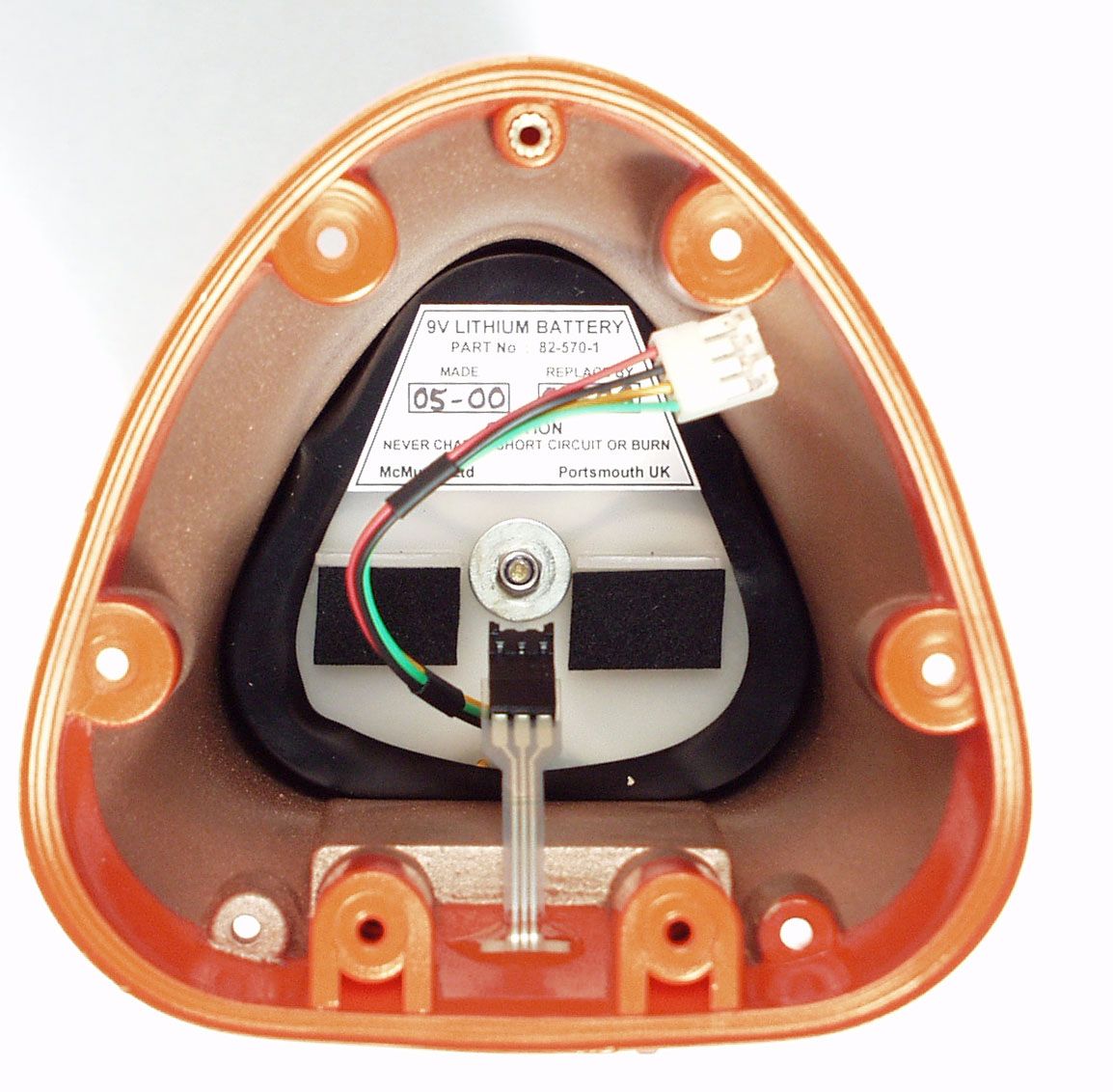
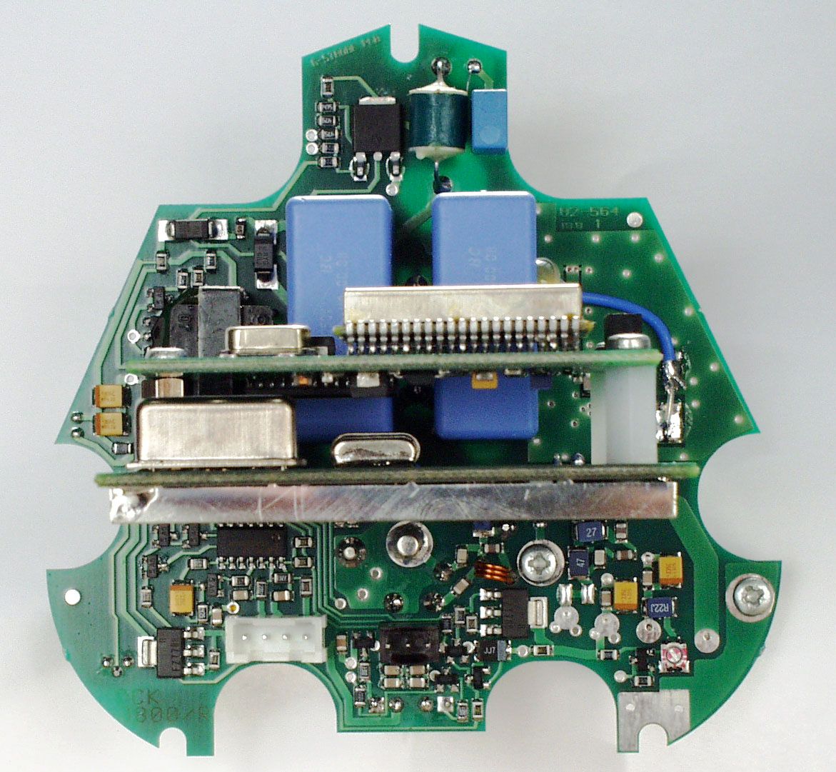
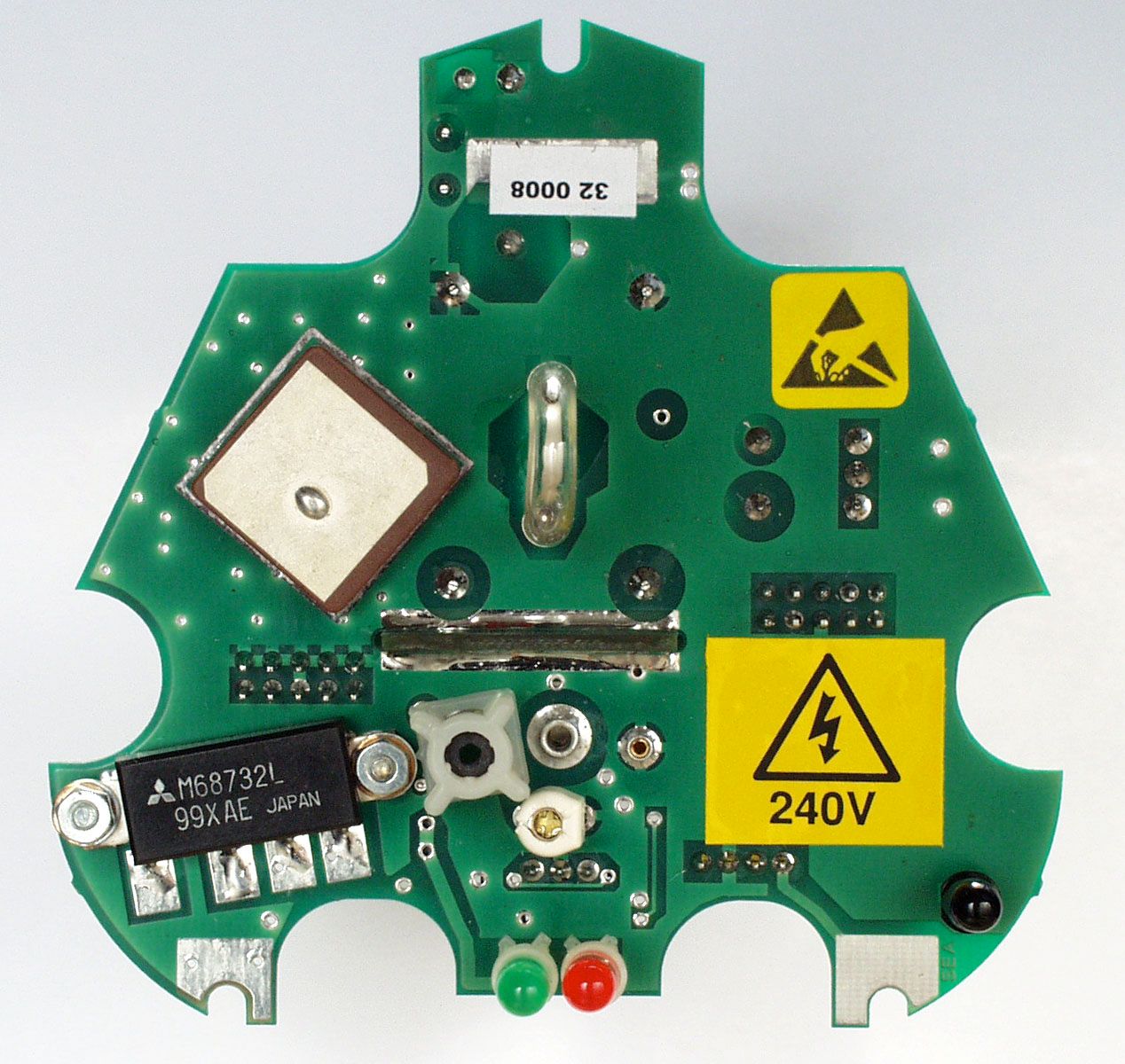
OPERATIONAL DESCRIPTION for McMurdo G4 406 GPS EPIRB: The G4 is a 406MHz float free satellite EPIRB with a built in 121.5MHz homing beacon and GPS module. It is used to locate a vessel or life raft in distress. When activated, the GPS module acquires and decodes the visible GPS satellites data transmissions, and calculates a position solution. If the number of satellites used in the calculation is greater then 3 and the HDOP, (Horizontal Dilution of precision), is less than 4, then the position data is encoded into the 406 message and transmitted, enabling identification of the vessel and its position, to better than 100m. If no valid GPS data is available, a default position is encoded into the 406 message In this mode, Doppler shift position calculation is used giving a position accuracy of typically 3 km. The EPIRB comes complete with an automatic release mechanism. BEACON DESCRIPTION The G4 consists of two mouldings, a transparent top dome made from Polycarbonate and a main body made from a Polycarbonate/ABS thermoplastic mix. The main body is internally sprayed with a conductive coating to achieve good EMC performance. The two mouldings are screwed together. A gasket made from Sarlink, which is a thermoplastic elastomer, is used to provide a waterproof seal. The bottom moulding contains the battery pack and a counter balance weight to give good buoyancy characteristics. On the rear of the moulding are two seawater switch contacts and two membrane switches. One membrane switch is labelled HOLD TO TEST/READY and the other is labelled ON. The ON switch is protected against inadvertent use by a plastic cover fitted with a tamper seal. The EPIRB cannot be manually operated unless the tamper seal is removed and the plastic cover slid across to the left of the moulding. The bottom moulding also houses the EPIRB electronics, which are contained on three printed circuit boards. The two main boards are configured as a ‘T’ with the GPS daughter board mounted on spacers on the rear of the vertical board. The top dome is transparent so that Xenon tube is clearly visible. The top dome also provides the mechanical fixing for the 406MHz/121.5MHz antenna. A recess in the moulding allows for aligning a light pen for infra-red data programming. The G4 is programmed via an infra-red data link. This means that a vessel’s unique identity number can be programmed into the G4 via a RS232 interface. This data is then permanently stored in the EPIRB. This system enables swift and easy programming of the EPIRB without having to break the watertight seal. RELEASE MECHANISM The G4 is protected in a ‘floatfree’ two-part housing which provides safe storage for the EPIRB until it is required for use. The two-part housing is made from Acrylate Styrene Acrylonitrile, which is a thermoplastic material. The bottom half contains the release mechanism and is designed to be bolted to a bulkhead. The release mechanism consists of a stainless steel bracket to support the EPIRB, a spring and a hydrostatic release unit. The bracket containing the EPIRB compresses the spring, and is held in place by a nylon 8mm rod that passes through the hydrostatic release and is secured using a circlip at the base of the bottom housing. The top and bottom housings are then secured together with the aid of an R clip passed through the nylon rod which protrudes through the top housing. The hydrostatic release will operate at a depth of 1.5m-4m. Once activated the hydrostatic release cuts the nylon rod. This releases the spring and forces the two halves apart allowing the EPIRB to float to the surface.
Operational Description
G4 GPS EPIRB Technical Specification General Approved toCOSPAS-SARSAT T.001 class 2 RTCM SC110-STD Version 2 class 2 ETS 300 066 IEC 1097-2 Complies withEN 60945 Part 80 of FCC regulations Operating temperature range-20ºC to +55ºC Storage temperature range-30ºC to +70ºC Operational life48 hours minimum at -20ºC Battery type9V lithium manganese dioxide Battery expiry6 years from date of manufacture Electrical 406.025MHz transmitter Frequency406.028MHz + 3KHz Output power5W + 2dB Data encodingBi-phase L ModulationPhase modulation: 1.1 rads + 0.1 rads Transmission time520ms + 1% Repetition period50 secs + 2.5 secs 121.5MHz homing transmitter Frequency121.5MHz + 3KHz Output power50mW + 3dB PERP Transmit duty cycleContinuous Modulation format3K20A3X Modulation frequency sweep1300Hz to 350Hz Modulation duty cycle41% + 5% Sweep repetition rate3Hz + 1Hz Sweep directionProgrammable UP or DOWN GPS receiver/engine Centre frequencyBand L1. 1.57542GHz Received signal sensitivity-175dBW minimum. Maximum number of satellites tracked12 Transmit Antenna TypeFlexible, vertical whip CharacteristicsVertically polarised, omni-directional Receive Antenna TypeCeramic dielectric patch CharacteristicsRight hand circular polarised. Nominal +3dBi ga in. Optical Homer TypeXenon discharge tube Flash rate20 to 23 flashes per minute Light output> 0.75 candela over 75% of the horizontal plane External Interfaces Programming interfaceInfra-red link via RS232 port on a PC. Manual activationSealed membrane switch. Protected by sliding cover. Automatic activationSea water switch contacts. Activation within 5 seconds of immersion. Self testSealed membrane switch. Press and hold to activate self test. Confirmation of successful self test by 3 flashes of strobe light. Physical characteristics Weight730 grams nominal Height210mm to base of antenna. Width110.5mm at maximum
Parts List/Tune Up Info
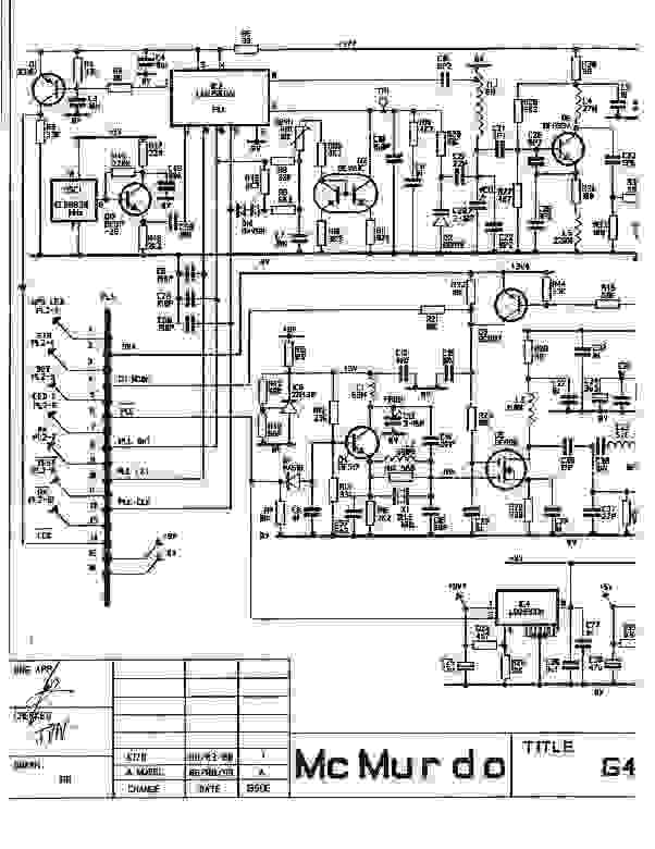
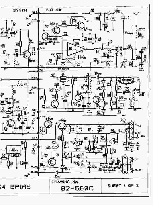
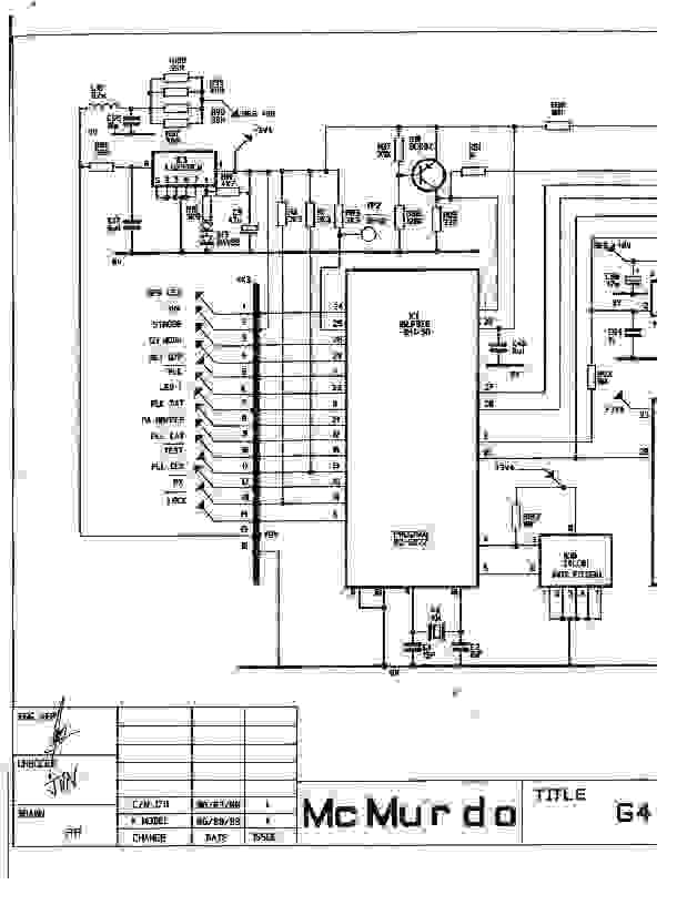
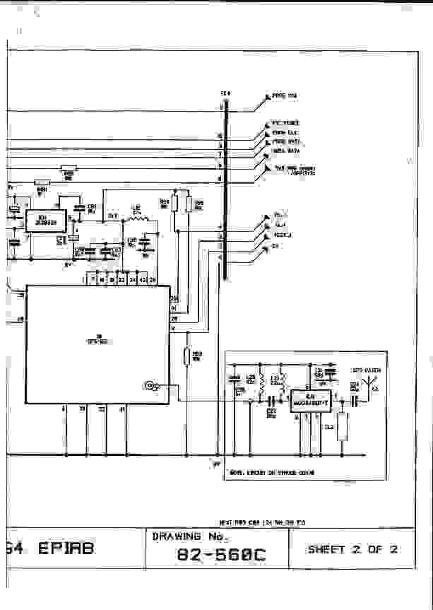
COMMERCIAL IN CONFIDENCE COMMERCIAL IN CONFIDENCE MCMURDO G4 406 GPS EPIRB FCC ID: KLS-82-501 CIRCUIT DESCRIPTION The G4 EPIRB is powered by three 3V3 Lithium Manganese Dioxide batteries connected in series, which gives a nominal operating voltage of 9.4V. The battery pack is protected by a 4A PTC. The battery pack is designed to last for at least 48hours at –20 deg C and be capable of supplying 1.8A pulses every 50 seconds. Refer to drawing 82-560C ACTIVATION The EPIRB is activated by energising Q13, this can be done by either pressing the ON membrane switch, the HOLD TO TEST membrane switch, or via the seawater switch contacts. The seawater switch operates when the resistance across the contacts is less then 47K ohms. This allows IC9d output to switch high. IC9c will switch low after a delay of 3 to 7 seconds due to the time constant formed by R65 and C55. This enables D14 to conduct and Q13 to turn on. In this state, the unit may only be turned off by removal from water. C55 will discharge through R78 causing Q10 to switch off after a delay of 3 to 7 seconds. The combination of IC9a and IC9b form a set-reset bistable. When the ON membrane switch is pressed, the output of IC9b switches low and is latched by IC9c switching low. D5 conducts, turning Q13 on. In this state the latch may only be reset by pressing the HOLD TO TEST switch. When the HOLD TO TEST membrane switch is pressed and held, D6 conducts allowing Q13 to turn on. The TST line to the microcontroller will also be pulled low via D3, causing the self-test routine to be initiated. Self Test 1) The ON LED illuminates. 2) The LCK line is checked to ensure that the PLL is locked. 3) After 7 seconds a 406MHz test message is made. The output of the RF detector is checked to ensure the correct power level. 4) The 121.5MHz homer performs three sweeps. The output of the RF detector is checked to ensure the correct power level. COMMERCIAL IN CONFIDENCE COMMERCIAL IN CONFIDENCE 5) The GPS module is powered up and the output data is checked to be the correct NMEA protocol. 6)If the levels and protocol are correct, the strobe flashes three times to indicate correct performance. MICRO-CONTROLLER The G4 EPIRB is controlled by IC1, an 8-bit microcontroller, with internal EEPROM. The microcontroller is responsible for all board operations. The microcontroller is powered by a 3V4 regulator, IC3, and run by 4MHz crystal X2. The micro-controller may be programmed during self-test with the data to be encoded in the 406 message. Data is input to the RX line from an infrared photodiode Q11, and stored in EEPROM. In operational mode the micro- controller provides the following control signals: 1) Every 2.6 seconds pulses the strobe trigger line high to flash the strobe 2) Flashes a red LED every 2.6 seconds to indicate normal operation. 3) Sets the PLL line high to enable the 121.5 MHz oscillator. 4) Generates frequency swept square waves on the MOD line to modulate the 121.5MHz transmission. 5) Every 50 seconds makes a 406MHz transmission. 6) Sets the PLL line low to enable the PLL and VCO circuits. 7) Loads division ratio data to the PLL via the LAT, DAT and CLK lines. 8) Sets the PA line high to enable the 406MHz PA. 9) Holds the DAT and CLK lines static for 160ms to generate unmodulated carrier. 10) Pulses the DAT and CLK lines for 360ms to phase modulate the carrier with encoded data. 11)Turns the GPS regulator, IC11, on for 5 minutes when initially activated and thereafter for 2 minutes every 20 minutes. 12)Accepts serial NMEA format data from the GPS module and encodes valid position data into the 406MHz message. 13)Flashes a green LED every 2.6 seconds when valid GPS data has been received. STROBE CIRCUIT Q15, T1 and C54 form an astable oscillator, running at 8KHz to 15KHz. The output waveform of the secondary of T1 is rectified by D8 to 300V and clamped at 270V by D11. Capacitors C69 and C70 are thus charged to 270V (and so is C68 via R79). The strobe trigger line is pulsed high for 2us every 2.6 seconds, forceing SCR1 to conduct. This causes C68 to discharge through the primary of T2, which generates a 3KV voltage across the Xenon tube, which causes the strobe to flash. Once C69 and C70 are discharged, the charging cycle repeats until clamped by D11. COMMERCIAL IN CONFIDENCE COMMERCIAL IN CONFIDENCE 121.5MHz TRANSMITTER The transistor Q4 forms part of a modified crystal controlled Colpitts oscillator, IC6 is a programmable regulator which supplies the oscillator with a regulated 5V supply. The oscillator is switched on and off by the microcontroller via D1 and R7. FET Q5 is a modulator/buffer. Amplitude modulation of the 121.5MHz signal is generated by the microcontroller. Modulation is in the form of a square wave, swept down from 1300Hz to 600Hz, with a duty cycle of 41%. The FET modulator/buffer produces an output power of 8dBm that drives the power amplifier Q8. The power amplifier is operated in Class C mode and produces an output of 20dBm. The output of the power amplifier is fed to a diplexer. The diplexer acts to combine the 121.5MHz signal with the 406MHz signal which is then output to the antenna via the antenna tuning unit (A.T.U). The 121.5MHz output power level is detected and converted to a DC level by the network C67, L15 and D9. This level is monitored during the self-test sequence to confirm the correct operation of the 121.5MHz circuit. 406MHz TRANSMITTER During normal operation of the G4 EPIRB, all 406MHz circuitry, except for the 5V supply to the ovened oscillator OSC1, is shut down. The 406MHz transmission sequence starts when pin 8 of IC1 switches LOW. This enables regulator IC4, powering the 406MHz synthesiser and VCO circuits. A short time later, the 406MHz PA is enabled by pin 1 of the microcontroller switching high. At the end of the 520ms transmission, the PA, synthesiser and VCO circuits are shut down. 406MHz synthesiser The 406MHz phase locked loop comprises of a high performance programmable synthesiser, IC2, …
Text truncated - open the document above for the full version.
Parts List/Tune Up Info
COMMERCIAL IN CONFIDENCE COMMERCIAL IN CONFIDENCE MCMURDO G4 406 GPS EPIRB FCC ID: KLS-82-501 CIRCUIT DESCRIPTION The G4 EPIRB is powered by three 3V3 Lithium Manganese Dioxide batteries connected in series, which gives a nominal operating voltage of 9.4V. The battery pack is protected by a 4A PTC. The battery pack is designed to last for at least 48hours at –20 deg C and be capable of supplying 1.8A pulses every 50 seconds. Refer to drawing 82-560C ACTIVATION The EPIRB is activated by energising Q13, this can be done by either pressing the ON membrane switch, the HOLD TO TEST membrane switch, or via the seawater switch contacts. The seawater switch operates when the resistance across the contacts is less then 47K ohms. This allows IC9d output to switch high. IC9c will switch low after a delay of 3 to 7 seconds due to the time constant formed by R65 and C55. This enables D14 to conduct and Q13 to turn on. In this state, the unit may only be turned off by removal from water. C55 will discharge through R78 causing Q10 to switch off after a delay of 3 to 7 seconds. The combination of IC9a and IC9b form a set-reset bistable. When the ON membrane switch is pressed, the output of IC9b switches low and is latched by IC9c switching low. D5 conducts, turning Q13 on. In this state the latch may only be reset by pressing the HOLD TO TEST switch. When the HOLD TO TEST membrane switch is pressed and held, D6 conducts allowing Q13 to turn on. The TST line to the microcontroller will also be pulled low via D3, causing the self-test routine to be initiated. Self Test 1) The ON LED illuminates. 2) The LCK line is checked to ensure that the PLL is locked. 3) After 7 seconds a 406MHz test message is made. The output of the RF detector is checked to ensure the correct power level. 4) The 121.5MHz homer performs three sweeps. The output of the RF detector is checked to ensure the correct power level. COMMERCIAL IN CONFIDENCE COMMERCIAL IN CONFIDENCE 5) The GPS module is powered up and the output data is checked to be the correct NMEA protocol. 6)If the levels and protocol are correct, the strobe flashes three times to indicate correct performance. MICRO-CONTROLLER The G4 EPIRB is controlled by IC1, an 8-bit microcontroller, with internal EEPROM. The microcontroller is responsible for all board operations. The microcontroller is powered by a 3V4 regulator, IC3, and run by 4MHz crystal X2. The micro-controller may be program…
Text truncated - open the document above for the full version.
Contact Information
Applicant
Erwan Thomas(Certification and hardware engineer)
Technical Contact
Non-Technical Contact
McMurdo LtdSteve J Metcalf
[email protected]+44 2392 775042
Technical Specifications
| # | Rule Parts | Frequency Range | Power Output | Emission | Tolerance |
|---|---|---|---|---|---|
| 2 | 80.1101(c)(6) | 406.028 MHz - 406.028 MHz | 4 W | 16K0G1D | 1000 Hz |
Other Applications from Orolia Ltd

KLS-Z502
Apr 19, 2012AIS-MSLD
Equipment Class
AIS - Automatic Identification Systems
KLS-Z501
Apr 19, 2012AIS-MSLD
Equipment Class
AIS - Automatic Identification Systems
KLS-G5-2
Jul 10, 2011McMurdo Smartfind Plus G5, Sailor SGE406-II, Simrad EG50
Equipment Class
GEP - 406 MHz EPIRB
KLS-E5-2
Jul 10, 2011McMurdo Smartfind E5, Kannad Marine Automatic EPIRB, Kannad Marine Manual EPIRB, Sailor SE406-II, Simrad EP50
Equipment Class
GEP - 406 MHz EPIRB
KLS-PLB-4-GPS
Apr 05, 2011Fastfind MaxG, Safelink Pro, XS-ER GPS
Equipment Class
PLB - Personal Locator Beacons