KLS-M-2McMurdo Automatic Identification System
Orolia Ltd
Click to zoom
Application Details
- Equipment Class
- AIS - Automatic Identification Systems
- Date of Grant
- Feb 03, 2005
- Application Purpose
- Original Equipment
- Date of Application
- Dec 22, 2004
- Equipment Note
- McMurdo Automatic Identification System
- Frequency Range
- 156.52500000 - 156.52500000
- Company
- Orolia Ltd
- Country
- United Kingdom
Documents & Files
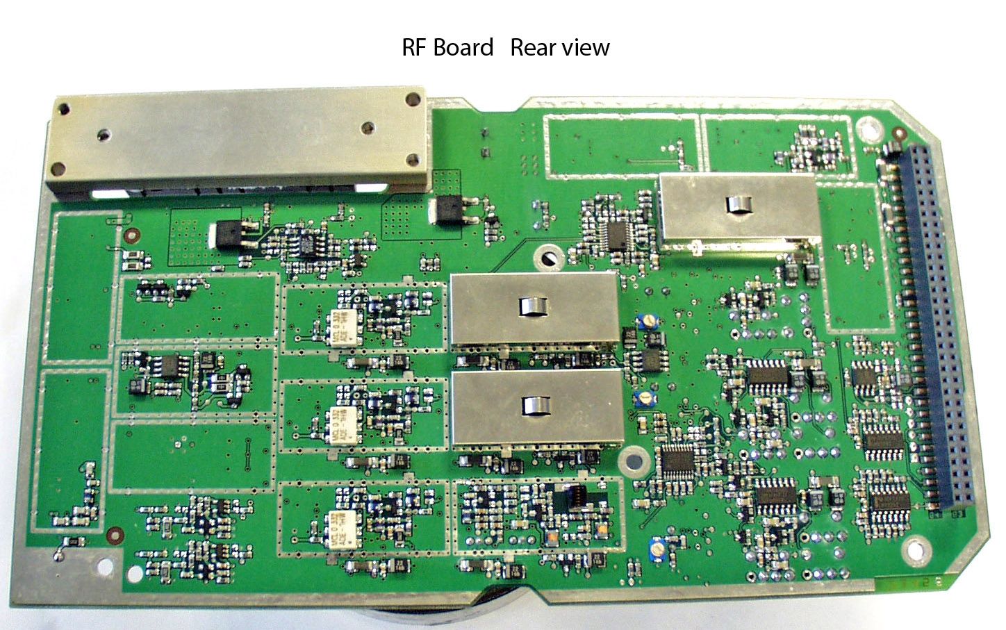
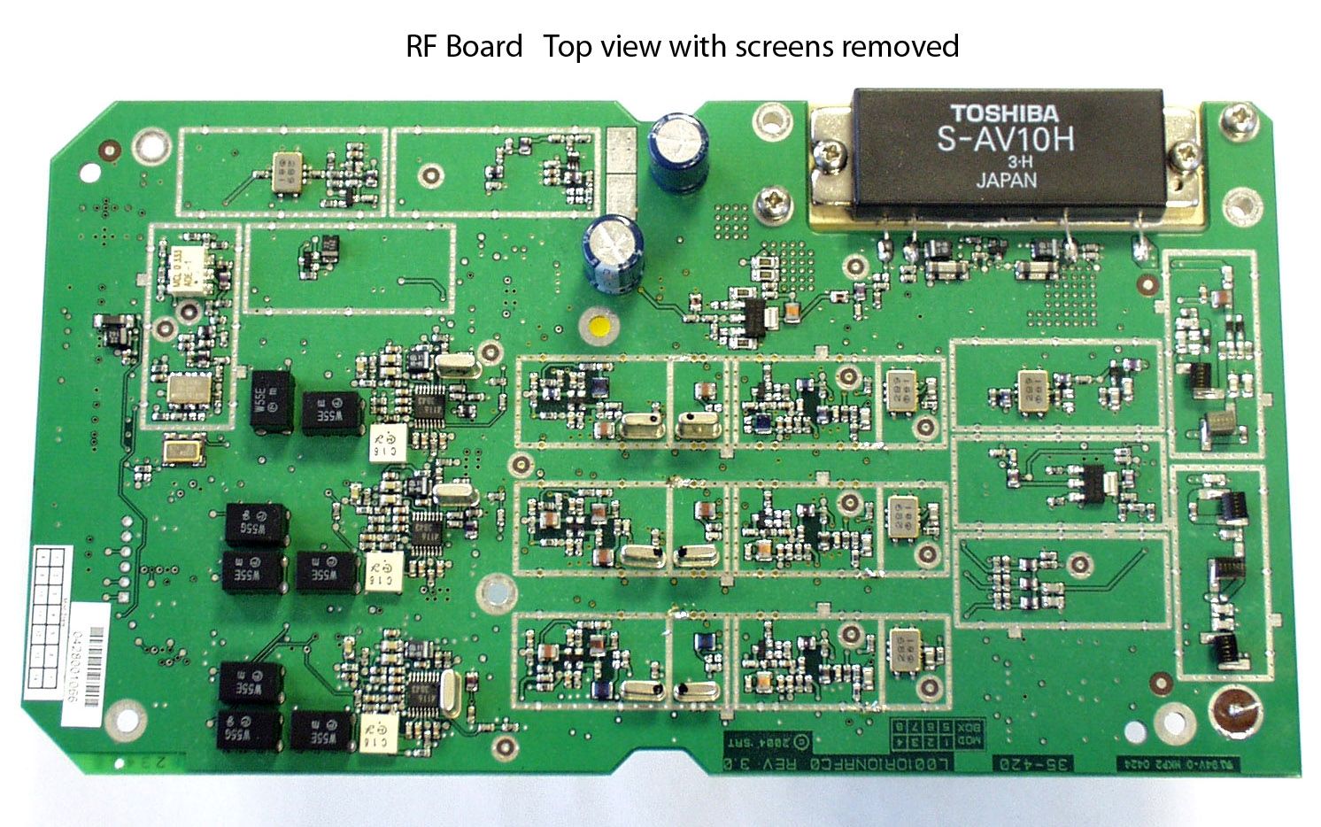
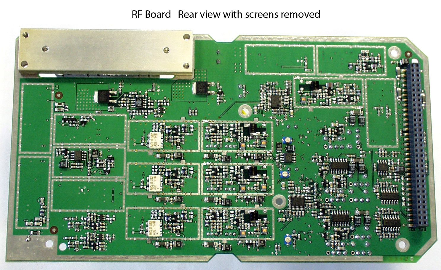
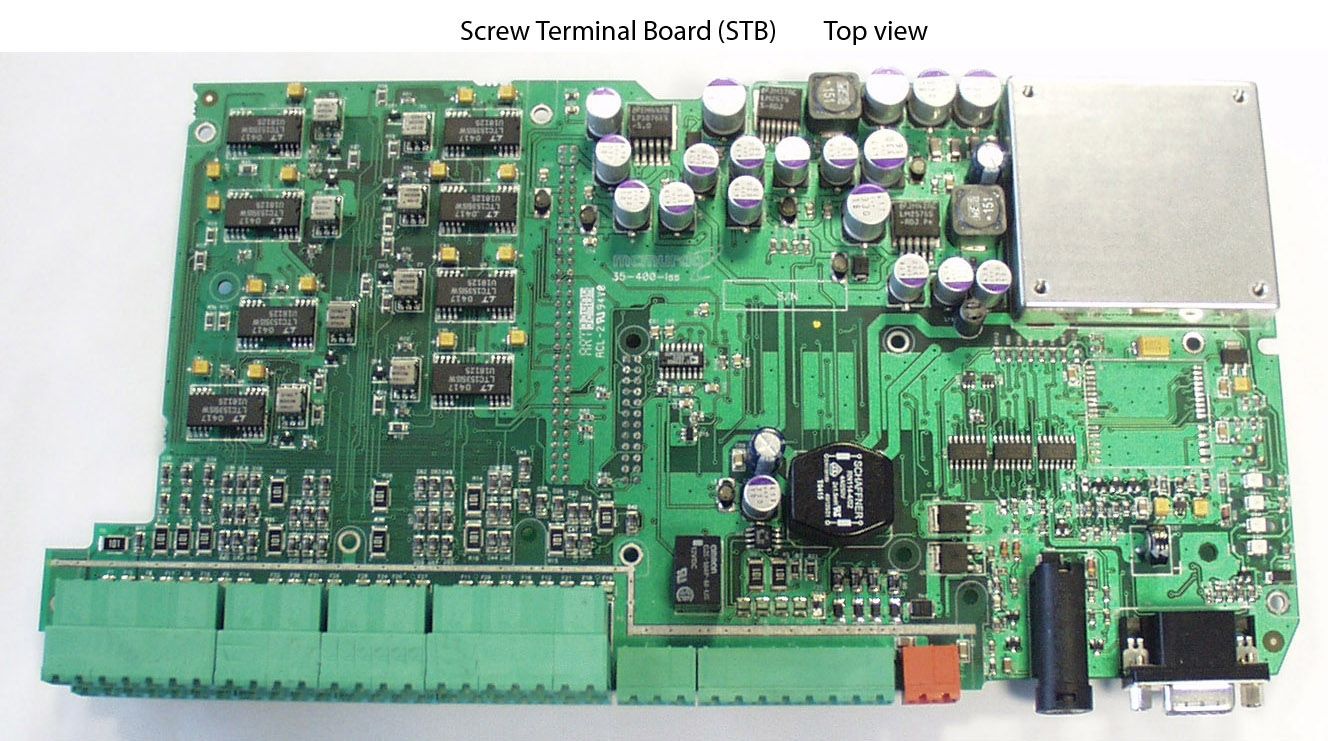
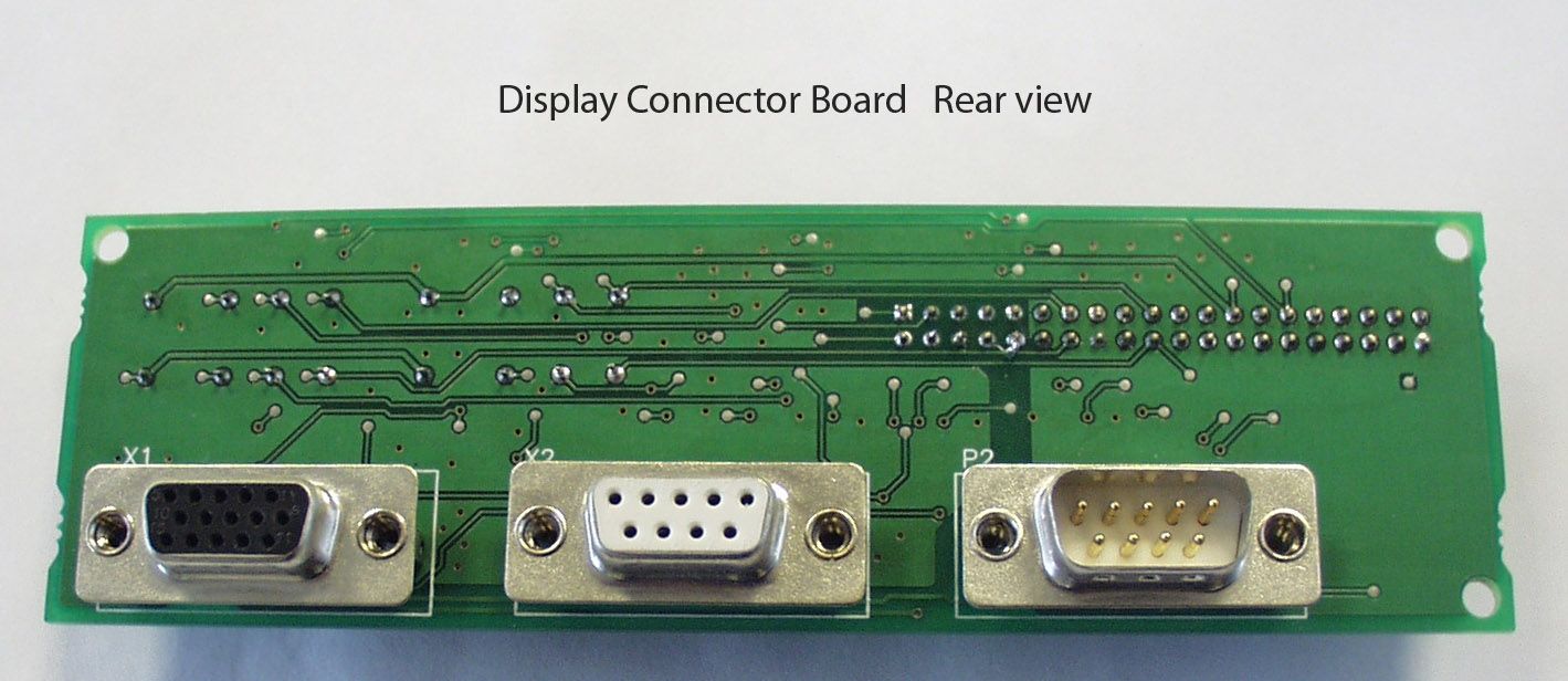
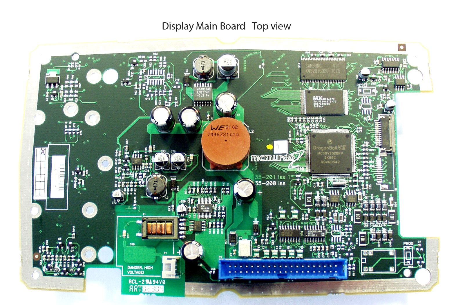
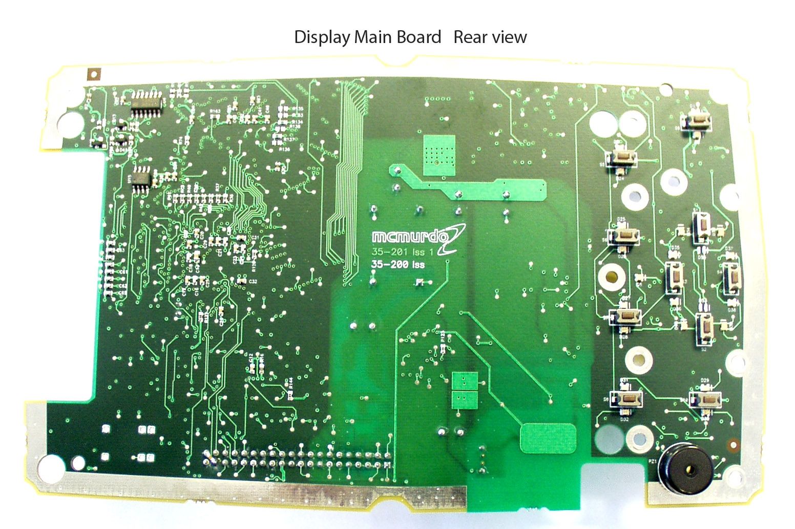
Document Text
Text extracted from the exhibit documents filed with the FCC. Open a document above to read the original.
Users Manual
Installation Manual M-2 AIS Transponder System 35-060-001 This page contains no other data Contents 1 PREFACE..................................................................................................................................1 2 INSTALLING THE AIS TRANSPONDER SYSTEM SAFELY........................................................2 3 INTRODUCTION........................................................................................................................5 3.1 ABOUT THIS MANUAL..............................................................................................................5 4 AIS TRANSPONDER SYSTEM...................................................................................................7 4.1 SYSTEM CONFIGURATION.......................................................................................................7 4.2 INSTALLATION ACCESSORIES...................................................................................................7 4.3 AIS BUILDING BLOCKS............................................................................................................7 5 MECHANICAL MOUNTING OPTIONS AND GUIDELINES..........................................................10 5.1 LOCATION...........................................................................................................................10 5.2 AIS TRANSPONDER UNIT.......................................................................................................10 5.2.1 Transponder main dimensions.....................................................................................10 5.3 AIS DISPLAY.......................................................................................................................13 5.3.1 AIS Display trunnion assembly.....................................................................................13 5.3.2 AIS Display flush mount assembly...............................................................................14 5.4 ANTENNA UNITS...................................................................................................................15 5.4.1 Antenna mounting position..........................................................................................15 5.4.2 VHF antenna..............................................................................................................15 5.4.3 GNSS antenna...........................................................................................................15 5.4.4 Weld on plate mounting of the GNSS antenna..............................................................16 5.4.5 Cable Preparation.......................................................................................................17 6 ELECTRICAL CONNECTIONS..................................................................................................19 6.1 GROUND CONNECTION..........................................................................................................19 6.2 SIGNAL CABLE CONNECTIONS FOR AIS TRANSPONDER...............................................................19 6.3 VHF AND GNSS (GPS) ANTENNA CABLE CONNECTIONS............................................................20 6.3.1 VHF antenna..............................................................................................................21 6.3.2 GNSS (GPS) antenna.................................................................................................21 6.4 CONNECTION TERMINALS.......................................................................................................22 6.4.1 Fuse values................................................................................................................22 6.4.2 Signal line termination.................................................................................................22 6.4.3 Method of connecting screens at the transponder.........................................................23 6.4.4 Test and program connections.....................................................................................24 6.4.5 Power supply..............................................................................................................24 6.4.6 DISP port – Display.....................................................................................................25 6.4.7 SEN 1, 2, 3, 4 ports - Sensors......................................................................................25 6.4.8 SEN Ports necessary sentences:.................................................................................26 6.4.9 Main and AUX high speed input/output ports................................................................26 6.4.10 MAIN port...................................................................................................................27 6.4.11 AUX/Pilot port.............................................................................................................27 6.4.12 Pilot Plug connection...................................................................................................27 6.4.13 Long Range Port.........................................................................................................27 6.4.14 RTCM port, Differential GNSS correction input/output port.............................................27 6.4.15 Alarm relay.................................................................................................................27 6.5 COMPLETION OF INSTALLATION...............................................................................................28 7 SPECIFICATION.......................................................................................................................29 7.1 TECHNICAL INFORMATION......................................................................................................30 7.1.1 RS-422 interfaces..................................................................…
Text truncated - open the document above for the full version.
Users Manual
Operation Manual M-2 AIS Transponder System Applicability of this manual This manual illustrates the operation of Display model V01.02.xx In accordance with McMurdo's policy of continual development and product improvement, equipment may be upgraded from time to time and future versions may therefore not correspond exactly with this manual. When necessary, upgrades will be accompanied by updates or addenda to this manual. Disclaimer Information contained in this manual is supplied in good faith, but is liable to change without notice. McMurdo Limited disclaims any liability for consequences arising from omissions or inaccuracies in the manuals and documentation provided with this product. IMPORTANT: Please take time to read this manual carefully and to understand its contents fully, so that you can operate your Transceiver correctly. © 2004 McMurdo Limited Safety Summary WARNING: ENSURE THAT THE M-2 AIS HAS BEEN CORRECTLY INSTALLED IN ACCORDANCE WITH IMO GUIDELINES AND THE SUPPLIED INSTALLATION MANUAL BEFORE POWERING ON THE SYSTEM. WARNING: The M-2 has no ON/OFF or power switch. It will automatically start operation within 2 minutes of applying power to the transponder unit. WARNING: Transponder chassis can become hot during extended periods of operation. Avoid touching this when the transponder is operating. The plastic dust cover must be fixed in place before setting the equipment to work. WARNING: Do not touch the VHF antenna or connecting cable when the transponder is in operation. WARNING: Unauthorised opening of the transponder access covers may invalidate the manufacturer’s warranty. WARNING: Avoid using chemical solvents to clean the Display or transponder dust cover as they can damage the casing material. WARNING: The use and operation of an AIS transponder is legislated and forms a part of the ship’s mandatory navigation equipment under SOLAS regulations. It is therefore necessary that the installation is certified (commissioned) and that certain information has to be available before full operation of the transponder can take place. The ship’s IMO and MMSI numbers and other important information must be entered as part of the installation and commissioning procedure, and before the equipment is used at sea. WARNING: This product is sold or provided as merely an aid to navigation. It is the responsibility of the user to exercise discretion and proper navigational and seamanship skills. WARNING: NOT ALL SHIPS CARRY AIS. The Officer of the Watch (OOW) should always be aware that other ships and, in particular, leisure craft, fishing boats and warships, and in some cases coastal shore stations (including Vessel Traffic Systems (VTS) centres), may not be fitted with AIS. The OOW should always be aware that AIS fitted on other ships as a mandatory carriage requirement may, under certain circumstances, be switched off based on the Master’s professional judgement. WARNING: The use of a Megger (High Voltage Insulation Tester) may damage the equipment and therefore should not be used. WARNING: Do not operate the equipment when persons are closer than 3 metres from the antenna. If any person (e.g. the operator) must be closer, then a grounded RF shield should be interposed between that person and the antenna. AIS Operation Licensing IMPORTANT: Operation of the AIS Transponder is covered by international radio regulations and therefore the ship must possess a valid ship’s radio licence. The AIS equipment must be correctly registered (Call Sign and MMSI number). Operation of AIS equipment without a valid MMSI number contravenes international radio regulations and must be avoided. Please contact the relevant authority in your country for further information regarding ship’s radio licensing requirements. Disclaimer Information contained in this manual is correct at time of going to print but is liable to change without notice. McMurdo Limited disclaims any liability for consequences arising from omissions or inaccuracies in the manuals and documentation provided with this product. Equipment may be upgraded and features added at any time; however, the basic principles given in this document will remain unchanged. Contents Introduction...............................................................................1 Product Definition..........................................................................2 AIS in use.....................................................................................3 M-2 Key AIS Functions..................................................................4 M-2 Product description.................................................................5 Quick Start - setting to work.................................................7 Starting the M-2.............................................................................7 Display and controls...............................................................8 Using Softkey menus...................................................................10 General operation.......................................................................11 General operation........................................................................12 Password access control.............................................................14 Detailed operation..................................................................17 VOYAGE Mode: Current Status....................................................18 VOYAGE Mode: Own Voyage......................................................19 Target Mode: Target list...............................................................21 Target Mode: Target Plot.............................................................22 Reading and sending safety messages.........................................24 Target Mode: All messages..........................................................25 Target Mode: Short messaging, Target message...........................28 Target mode: Short messaging, BROADCAST message..........…
Text truncated - open the document above for the full version.
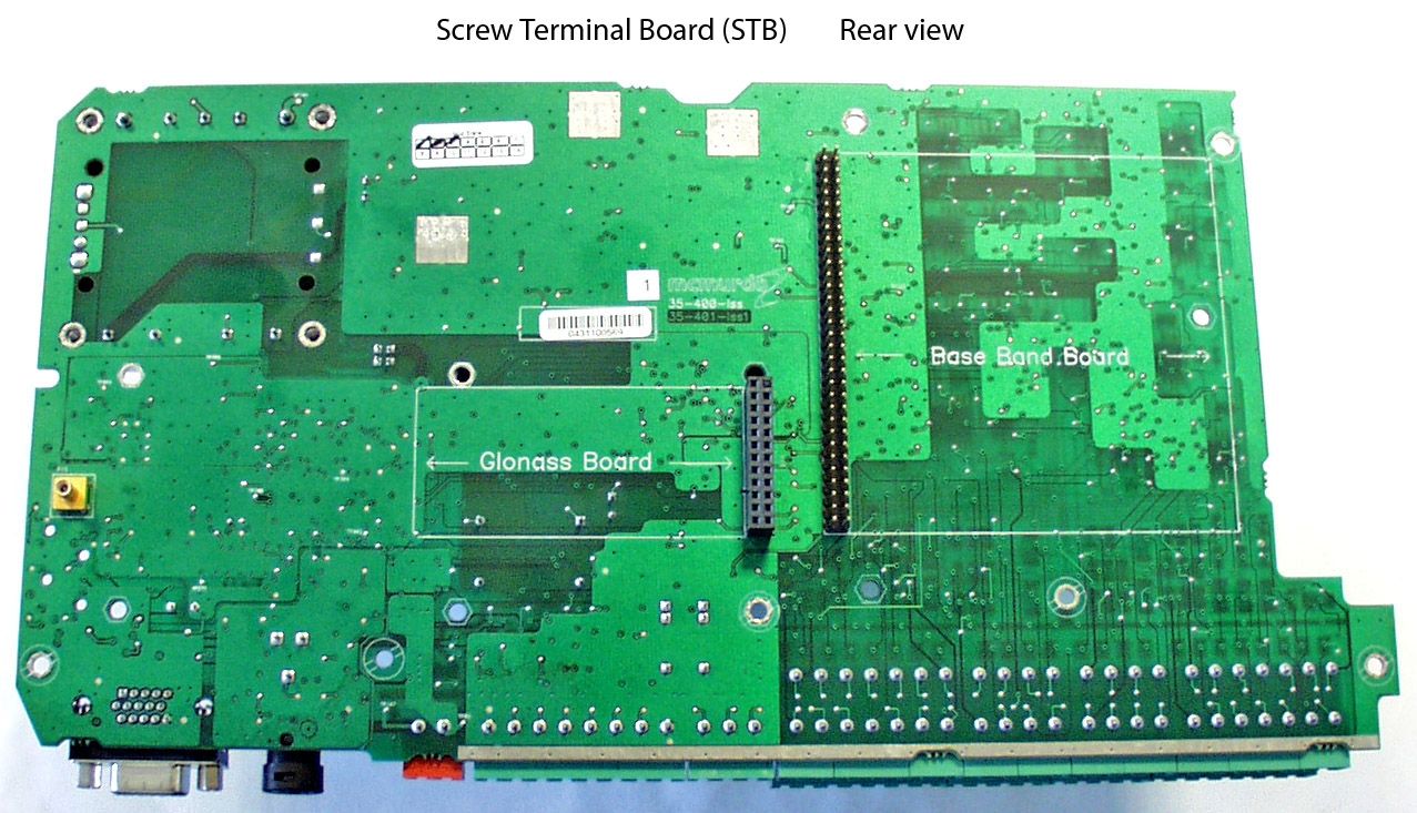
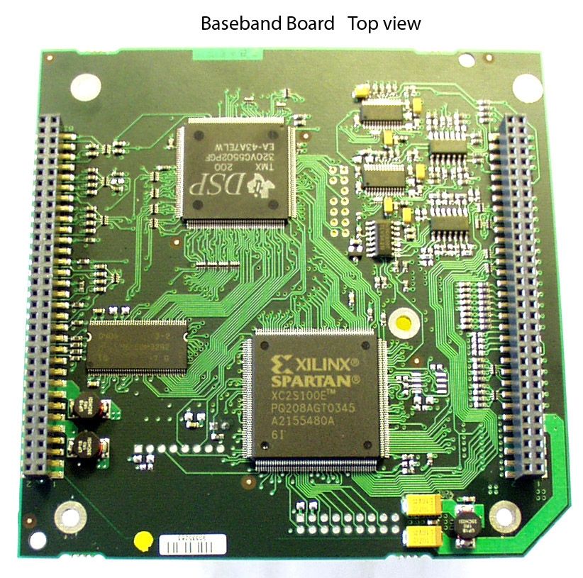
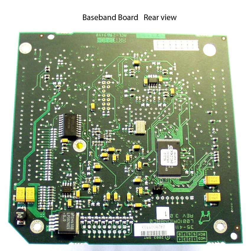
Block Diagram
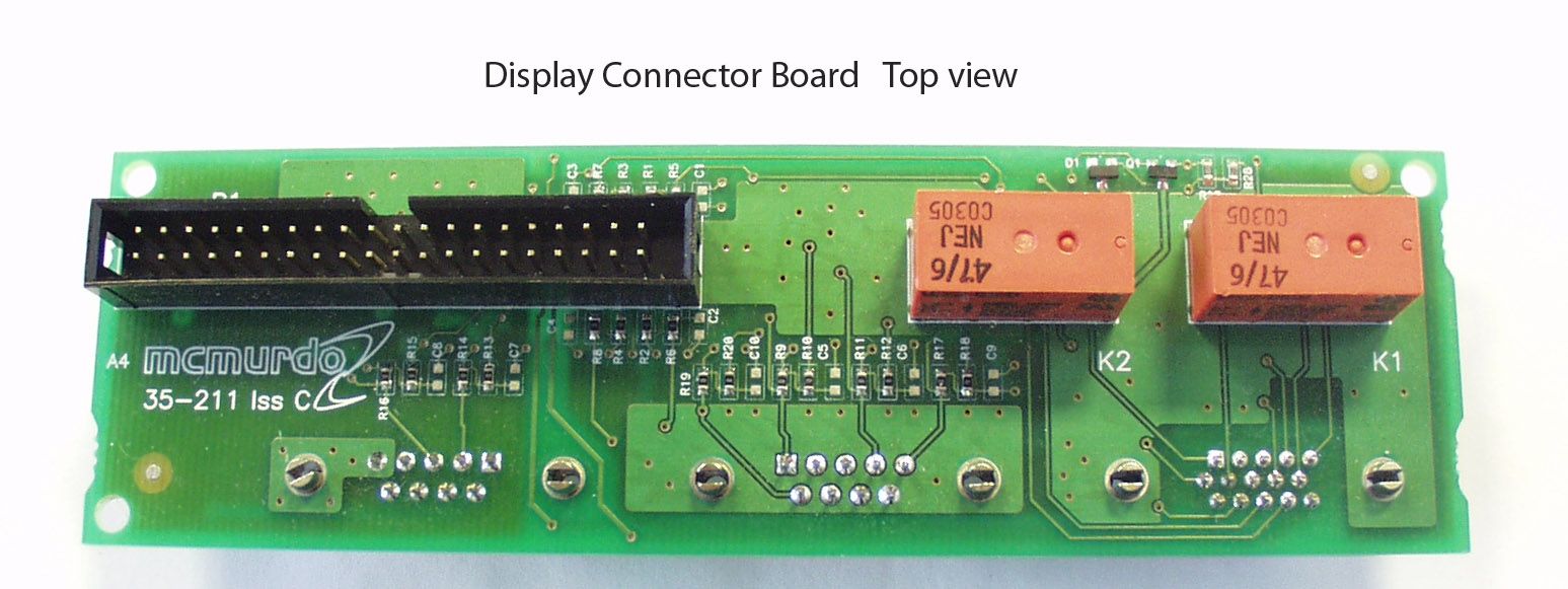
M2 A'S Design Document 2 Block Diagrams dsO36-04.doc Issue 05036-04 Issue 1Page I of 6 Amendment Record Issue DateAmendmentsWho 23 Dec 04First issue for comments and discussionN Taylor AuthorApproved by Project Manager SignatureSignature Name Oate Fadi Ibrahim 23 Oec 04 Name Oate Nick Taylor 23 Oec 04 No part of this document may be reproduced or transmitted in any form or by any means, electronic or mechanical, for any purpose without the express written permission of McMurdo Ltd. The information in this document is provided for reference only. McMurdo Limited does not assume any liability arising out of the application or use of the information or products described herein. !.9 2004 McMurdo Limited. All rights reserved 05036-04 Issue 1Page II of 6 Oescription: M-2 AIS PCB Block Oiagrams Number: Issue: 1 INTRODUCTION Scope ARCHITECTURE OF THE M-2 TRANSPONDER Block diagram - Complete System 2 35-410 RF PCB Block diagram - RF hardware 3 35-420 Baseband PCB Block diagram - Baseband pcb DSP subsystem 4 35-400 Screw Terminal (STB) PCB 2.4.STB Block diagram ARCHITECTURE OF THE M-2 MKD Block diagram - MKD 05036-04 Issue 1Page 3 of 6 Oescription: M-2 AIS PCB Block Oiagrams Number: Issue: 1 Introduction Scope This document provides block diagrams for the various hardware modules that are contained with the M-2 AIS transponder. 05036-04 Issue 1Page 4 of 6 Oescription: M-2 AIS PCB Block Oiagrams Number: Issue: 1 Architecture of the M-2 Transponder Block diagram - Complete System 24VDC GPS Antenna Isolated DC- Converter RS-232Pilot Connector MKD 13VD :g UARTS and signals MKD I terface RS-422 Interface ~ ~ ;:-1' '!! Interfaces ~ I :~0 - J Alarm Relay Alarm Relay TRANSPONDER M2-AIS Block Diagram Power Rails Board 35-420 TDMATDMADSC ontro Signals VHF Antenna Ships earth ---- Codec C5502 DSP + Memory ----------- CodecCodecCodec 05036-04 Issue 1 Spartan lie FPGA Baseband Board 35-410 Page 5 of 6 Oescription" Number" " 2 AIS PCB Block 0" Issue: 1 lagrams 35-410 RF PCB Block diagram - RFhardware 1st Rea;\,9r(.AlS) ;:::~"""~- ~~C"' -'c'"" "~"" 35-420 05036-04 Issue 1 coo Momm 1)( Offset Mx kcHtectlre Page 6 of 6 Oescription: M-2 AIS PCB Block Oiagrams Number: Issue: 1 35-420 Baseband PCB Block diagram - Baseband pcb Block diagram below shows the base band hardware architecture. JTAG H"'" "plnO. JTAG ToRF 35-420 TTL Synth 8,SV Tol""nt Inp~' 8 ". TTL O"'P"" Ston',,' Don,'ty IDC 0.05" C"" C""'ctom AIC23A STEREO CODEC.8K IIII IIII IIII GPIOA GPIOB Alarm Relay GPIOC""h"""") 5502A GOOMIP, '6V"" SLOTCLOCK Sensor1 INTn EMF BUS Sensor2 08T8 400 1;5 RESET EEPROM IMAGE RAM &SPI CONTROLLER Differential GPS Baseband 35410 Sp,"on", FPGA 1.8V"", XC'S100E Display 05036-04 Issue 1Page 7 of 6 Oescription: M-2 AIS PCB Block Oiagrams Number: Issue: 1 DSP subsystem 35-400 Screw Terminal (STB) PCB STB Block diagram Filtering and Protection 24VOCin GPS Antenna GPS Module DifCGPS +24V ~~- : Isolation --- 1-- PSUPSU +13V +6V 13V Interfaced to BIB Board '00mA Ant- Llnear.Reg +6V sensor2Sensor3 Switcher Switcher PildAUX +6V Linear Reg Screw Terminal Board 35-400 +5V 3atus LEOs Prog- inter Main Main 05036-04 Issue 1Page 8 of 6 Oescription: M-2 AIS PCB Block Oiagrams Number: Issue: 1 Architecture of the M-2 MKD Block diagram - MKD 13VOCIn Filtering Sub-D 15vvay and Pin 3&4 Protection Linear Reg 3V3 Supply Reset Power Fail Detect MKD Block Diagram for UAIS2 13VOC Buzzer Backlight LEOs Keyboard Contrast Voltage Bcklight Drive Motorola DragonBaIl Microoontrolier LCD Transponder Programming Interface v1aPC Pilot Plug 05036-04 Issue 1Page 9 of 6
Cover Letter(s)
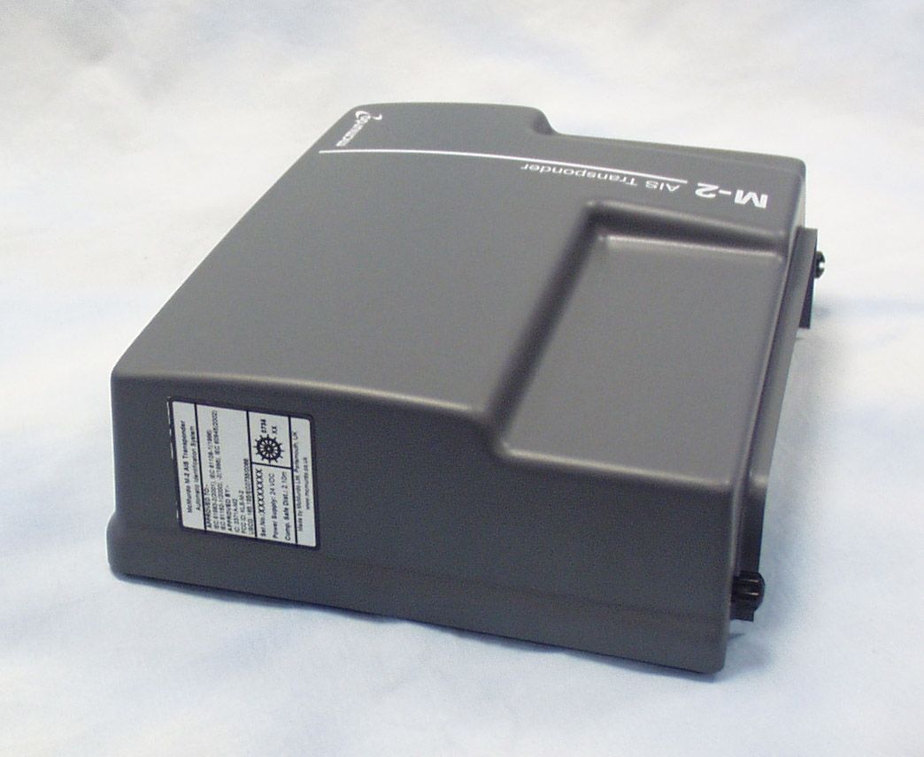
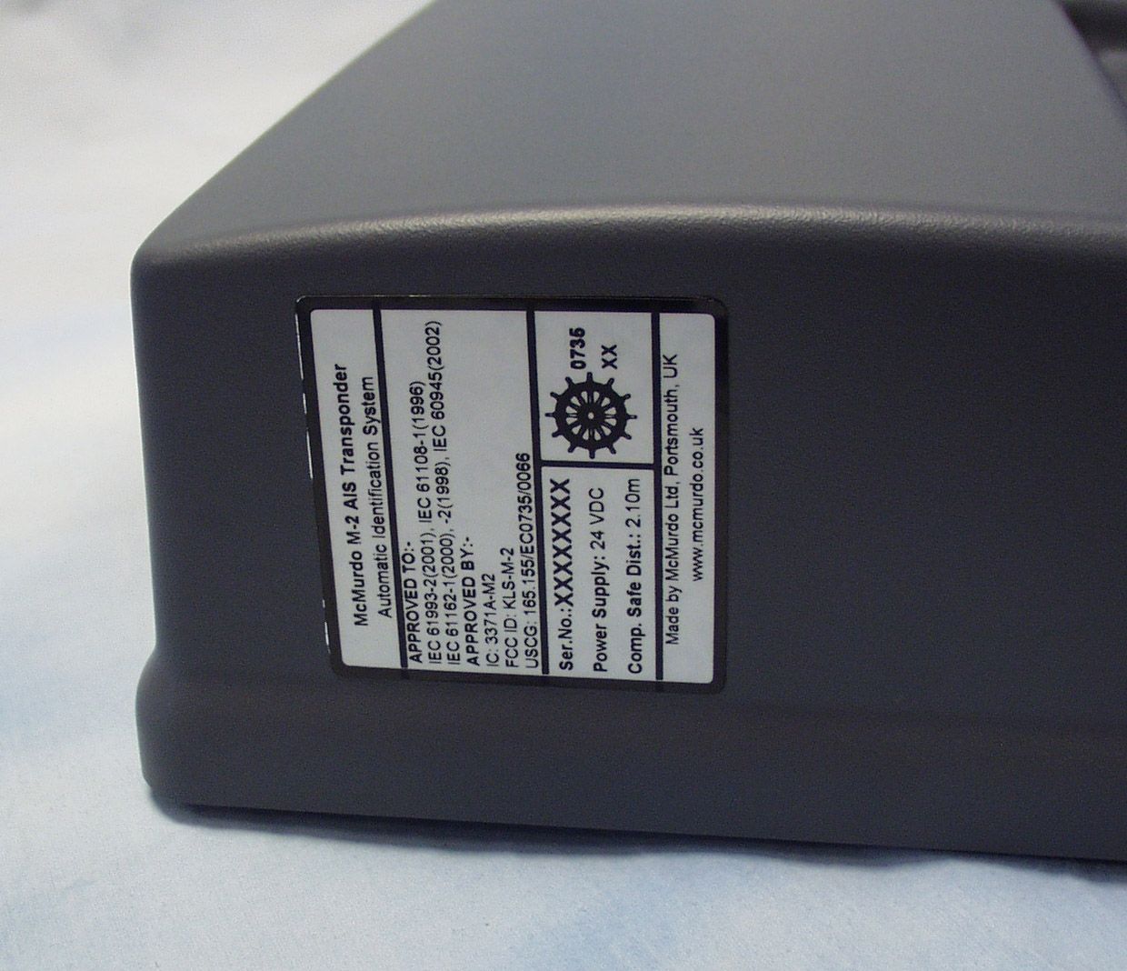
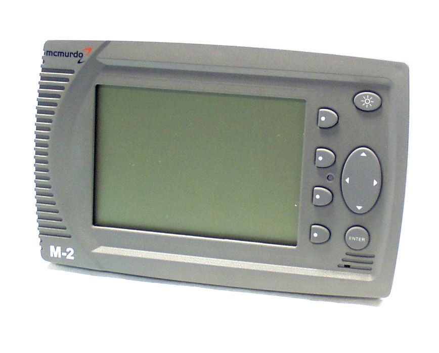
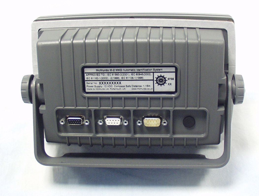
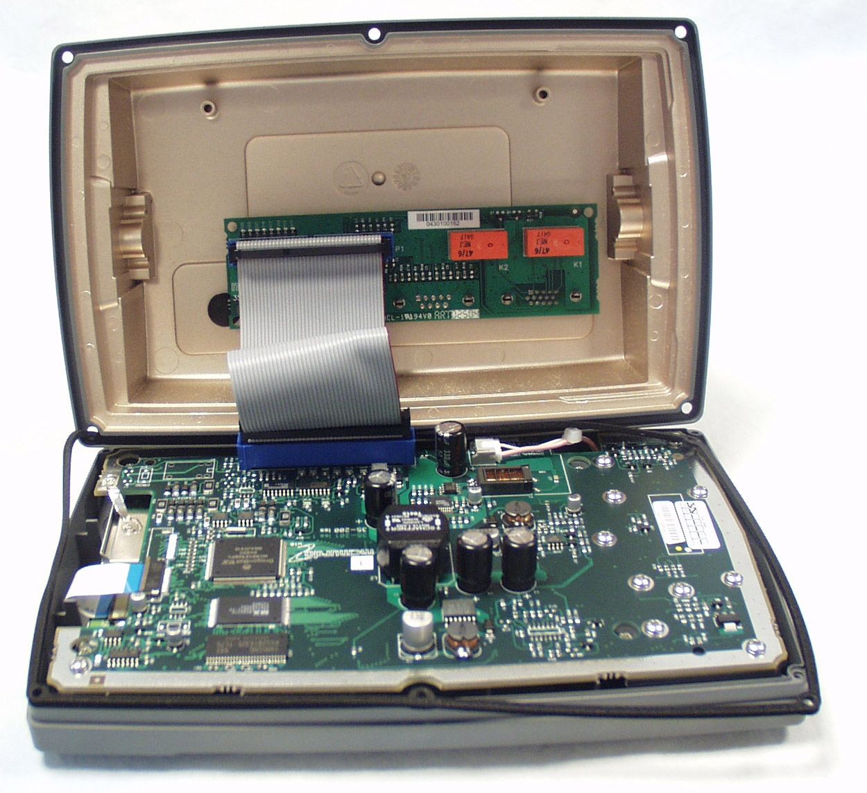
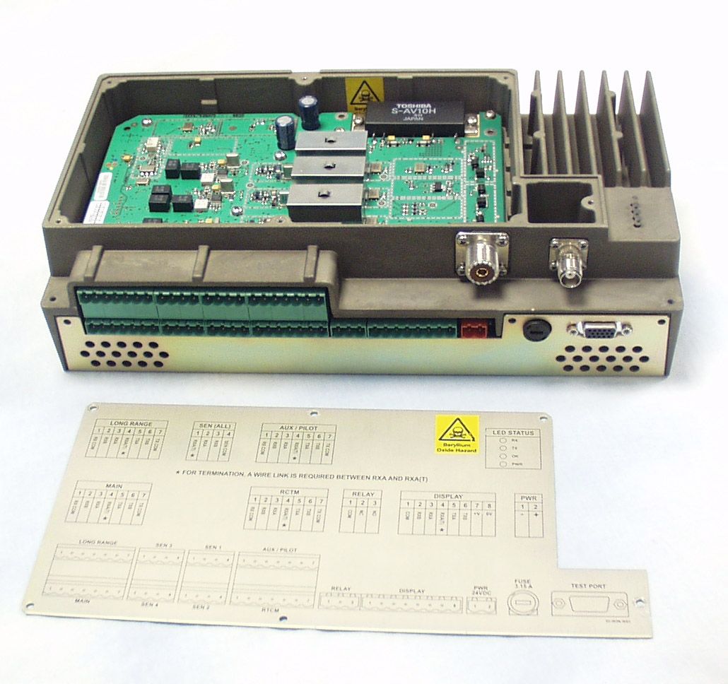
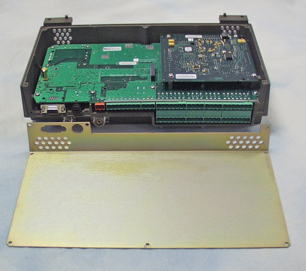
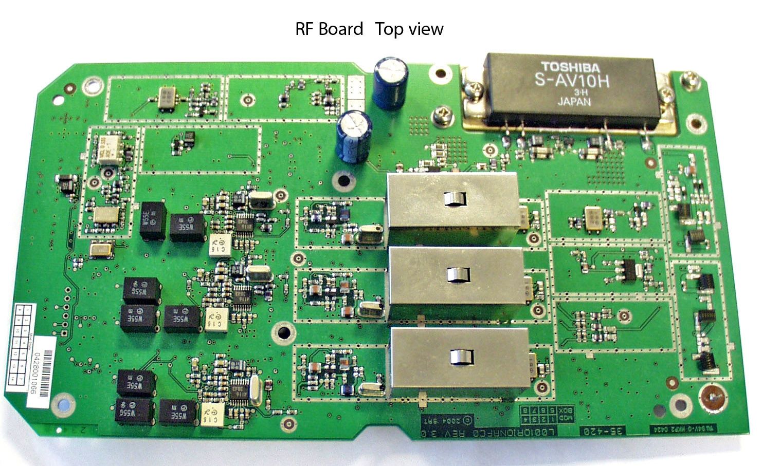
2 AIS Type Approval Submission - List of Exhibits for FCC Exhibit typeFile.pdfDescriptionConfidential Size Exhibit List 86KList of Exhibits (this document) Attestation 206KEC Type Examination (Module B) Statements 122KLloyds Register ISO 9001 2004 Certificate Block Diagrams 187KBlock Diagrams 036-04 Iss1 Covering Letter 71KFCC 47CFR80.373 Statement Drawings 145KCable Tray Drg 35-302D Iss2 83KChassis Bottom Panel Drg 35-304D Iss3 741K2 Chassis Assembly 35-300-xxxD Iss1 112KTransponder Assy Cover Drg 35-306D Iss3 206KTransponder Assy Drg 35-081-xxxD 249KTransponder Chassis Drg 35-301 D Iss6 41KTransponder Cover Drg 35-305-001 D Iss4 ID Labels 50K2 Transponder Approval Label Drg. 35-316-001 D Iss. 32K2 MKD Approval Label Drg. 35-120-001 D Iss. Operational 71KTechnical Description Doc 028-04 Iss1Yes Description Parts Lists 708KDisplay PCB Doc 35-200L Iss2Yes 725KTerminal board 35-400L Iss4Yes 603KTransponder baseband 35-410L Iss1Yes 2998KTransponder RF 35-420L Iss1.Yes Photos: External 377K2 Transponder External - Showing Front cover 736K2 Transponder External - Showing proposed approval label 248K2 Display External - Front view 432K2 Display External - Rear view showing label Photos: Internal 831K2 Display Internal - Front cover removed 503K2 Transponder Internal - Top 2 covers removed 605K2 Transponder Internal - Top & bottom covers removed Page 1 of2 Exhibit typeFile .pdfDescriptionConfidential Size Schematics 83KDisplay PCB Drg 35-200 Iss2 - Sheet 1Yes 54KDisplay PCB Drg 35-200 Iss2 - Sheet 2Yes 45KDisplay PCB Drg 35-200 Iss2 - Sheet 3Yes 51KDisplay PCB Drg 35-200 Iss2 - Sheet 4Yes 46KDisplay PCB Drg 35-200 Iss2 - Sheet 5Yes 45KDisplay PCB Drg 35-200 Iss2 - Sheet 6Yes 426KTerminal board 35-400C Iss3Yes 94KTransponder baseband 35-41 OC - Sheet 1Yes 89KTransponder baseband 35-41 OC - Sheet 2Yes 32KTransponder baseband 35-41 OC - Sheet 3Yes 42KTransponder baseband 35-41 OC - Sheet 4Yes 75KTransponder baseband 35-41 OC - Sheet 5Yes 39KTransponder baseband 35-41 OC - Sheet 6Yes 43KTransponder RF 35-420C Iss1.4 - Sheet Yes 25KTransponder RF 35-420C Iss1.4 - Sheet 2Yes 45KTransponder RF 35-420C Iss1.4 - Sheet 3Yes 33KTransponder RF 35-420C Iss1.4 - Sheet 4Yes 32KTransponder RF 35-420C Iss1.4 - Sheet 5Yes 42KTransponder RF 35-420C Iss1.4 - Sheet 6Yes 42KTransponder RF 35-420C Iss1.4 - Sheet 7Yes 42KTransponder RF 35-420C Iss1.4 - Sheet 8Yes 51KTransponder RF 35-420C Iss1.4 - Sheet 9Yes 51KTransponder RF 35-420C Iss1.4 - Sheet 10Yes Test Reports 2692K2 Telefication test report 99475930Yes 1808K2 Telefication Radio test report 99475920Yes 1570KBSH M-2 Final Test Report Part1Yes 1630KBSH M-2 Final Test Report Part2 AnnexYes User Manuals 2376K35-070-001 N Iss1 M-2 AIS Installation manual 1390K35-073-001 N Iss1 M-2 AIS Operation manual All files are Adobe Acrobat .PDF format except for photos which are JPEG graphic format WARNING: Where the Confidential column indicates Yes, the document is McMurdo copyright and contains proprietary owned intellectual property rights and confidential data. All rights are strictly reserved. The information must be used only for the agreed purpose. Unauthorised use reproduction or issue to any third party is not permitted without the prior written agreement of McMurdo Limited. Page 2 of 2
Test Report
Radio test report 99475930 based on: IEC 61993-2 First edition 2001 Class A Shipborne AIS equipment McMurdo M2 Report number: 99475930 Contents MAIN MODULE..............................................................................................................................................4 1 Introduction.................................................................................................................................4 2 Product ........................................................................................................................................5 3 Test schedule...............................................................................................................................5 4 Product documentation ...............................................................................................................5 5 Hardware list ...............................................................................................................................6 MKD ...................................................................................................................................6 6 Software list ................................................................................................................................6 Transponder ........................................................................................................................6 Software file........................................................................................................................6 7 Observations and comments .......................................................................................................6 8 Summary .....................................................................................................................................6 9 Conclusions.................................................................................................................................7 TEST RESULTS MODULE ...........................................................................................................................8 1 Summary .....................................................................................................................................9 2 Test results ................................................................................................................................10 2.1 4.1.4 Transmitter shutdown ..............................................................................................10 2.2 4.4 Marking & identification ............................................................................................10 2.3 14.8 Transceiver protection...............................................................................................10 2.4 15.1 TDMA Transmitter ...................................................................................................11 2.4.1 15.1.1 Frequency Error .............................................................................................11 2.4.2 15.1.2 Carrier Power .................................................................................................12 2.4.3 15.1.3 Modulation Spectrum 25 kHz channel mode .................................................13 2.4.3.1 GMSK Spectrum TDMA at 156.025 MHz ...........................................................13 2.4.3.2 GMSK Spectrum TDMA at 162.025 MHz ...........................................................15 2.4.3.3 AFSK Spectrum DSC at 156.525 MHz ................................................................17 2.4.4 15.1.4 Modulation Spectrum 12.5 kHz channel mode ..............................................18 2.4.4.1 GMSK Spectrum TDMA at 156.025 MHz ...........................................................18 2.4.4.2 GMSK Spectrum TDMA at 162.025 MHz ...........................................................20 2.4.5 15.1.5 Transmitter Attack Time ................................................................................22 2.4.6 15.1.6 Transmitter Release Time ..............................................................................23 2.5 15.2 DSC Transmissions...................................................................................................24 2.5.1 15.2.1 Frequency error of the DSC Signal ................................................................24 2.5.2 15.2.2 Modulation Rate.............................................................................................25 2.6 15.3 TDMA Receivers ......................................................................................................26 2.6.1 15.3.1 Sensitivity - 25 kHz Operation.......................................................................26 2.6.2 15.3.2 Sensitivity - 12.5 kHz Operation....................................................................27 2.6.3 15.3.3 Error Behaviour at High Input Levels............................................................28 2.6.4 15.3.4 Co-channel Rejection - 25 kHz Operation ....................................................29 2.6.5 15.3.5 Co-channel Rejection - 12.5 kHz Operation .................................................30 2.6.6 15.3.6 Adjacent Channel selectivity - 25 kHz Operation..........................................31 2.6.7 15.3.7 Adjacent Channel selectivity - 12.5 kHz Operation.......................................32 2.6.8 15.3.8 Spurious Response Rejection at 156.025 MHz ..............................................33 2.6.9 15.3.8 Spurious Response Rejection at 162.025 MHz ..............................................34 2.6.10 15.3.9 Intermodulation response rejection and blocking ..........................................35 2.6.11 15.3.10 Transmit to receive switching time ..............................................................36 Report number: 99475930 2.7 15.4 DSC Receiver..............................................................................................…
Text truncated - open the document above for the full version.
Test Report
Test report 99475920 based on: EN 60945, issue 4 : 2002-11 Class A Shipborne AIS equipment McMurdo M2 Report number: 99475920 Contents MAIN MODULE..............................................................................................................................................4 1 Introduction.............................................................................................................................4 2 Product ....................................................................................................................................5 3 Test schedule...........................................................................................................................5 4 Product documentation ...........................................................................................................5 5 Hardware list ...........................................................................................................................6 MKD ...............................................................................................................................6 6 Software list ............................................................................................................................6 Transponder ....................................................................................................................6 Software file....................................................................................................................6 7 List of ports .............................................................................................................................6 8 Observations and comments ...................................................................................................7 9 Uncertainty of measurement ...................................................................................................7 10 Technical specifications ......................................................................................................8 11 Summary .............................................................................................................................9 12 Conclusions.......................................................................................................................10 TEST RESULTS MODULE .........................................................................................................................11 1 Power supply – Methods of testing and test results according to EN60945 clause 7 ...........12 1.1 Extreme power supply ..................................................................................................12 1.2 Excessive conditions .....................................................................................................12 1.3 Power supply short-term variation ................................................................................12 1.4 Power supply failure .....................................................................................................12 2 Durability and resistance to environmental conditions according to EN60945 clause 8 ......13 2.1 General (8.1) .................................................................................................................14 2.2 Dry heat functional test .................................................................................................15 2.3 Damp heat functional test .............................................................................................16 2.4 Low temperature functional test ...................................................................................17 2.5 Vibration .......................................................................................................................18 3 Electromagnetic emission clause 9 .......................................................................................21 3.1 Summary .......................................................................................................................21 3.2 Conducted emissions 10 kHz - 150 kHz .......................................................................22 3.3 Conducted emissions 150 kHz - 30 MHz .....................................................................24 3.4 Radiated emissions 150 kHz - 30 MHz.........................................................................26 3.4.1 Plot radiated emissions 150 kHz - 30 MHz ..............................................................27 3.5 Radiated emissions 30 MHz - 1 GHz............................................................................28 3.5.1 Plot radiated emissions 30 MHz - 1000 MHz Vertical .............................................29 3.5.2 Plot radiated emissions 30 MHz - 1000 MHz Horizontal .........................................29 3.6 Radiated emissions 156 MHz - 165 MHz .....................................................................30 3.6.1 Plot radiated emissions 156 - 165 MHz Vertical ......................................................31 3.6.2 Plot radiated emissions 156 - 165 MHz Horizontal ......................................…
Text truncated - open the document above for the full version.
Contact Information
Applicant
Erwan Thomas(Certification and hardware engineer)
Technical Contact
McMurdo LimitedNick Taylor
[email protected]+44(0)2392623975
Silverpoint · Portsmouth · United Kingdom
Non-Technical Contact
McMurdo LimitedDerek Carr
[email protected]+44(0)2392623940
Technical Specifications
| # | Rule Parts | Frequency Range | Power Output | Emission | Tolerance |
|---|---|---|---|---|---|
| 3 | 8 | 156.525 MHz - 156.525 MHz | 12.5 W | 14K2G2B | 1000 Hz |
Other Applications from Orolia Ltd

KLS-Z502
Apr 19, 2012AIS-MSLD
Equipment Class
AIS - Automatic Identification Systems
KLS-Z501
Apr 19, 2012AIS-MSLD
Equipment Class
AIS - Automatic Identification Systems
KLS-G5-2
Jul 10, 2011McMurdo Smartfind Plus G5, Sailor SGE406-II, Simrad EG50
Equipment Class
GEP - 406 MHz EPIRB
KLS-E5-2
Jul 10, 2011McMurdo Smartfind E5, Kannad Marine Automatic EPIRB, Kannad Marine Manual EPIRB, Sailor SE406-II, Simrad EP50
Equipment Class
GEP - 406 MHz EPIRB
KLS-PLB-4-GPS
Apr 05, 2011Fastfind MaxG, Safelink Pro, XS-ER GPS
Equipment Class
PLB - Personal Locator Beacons