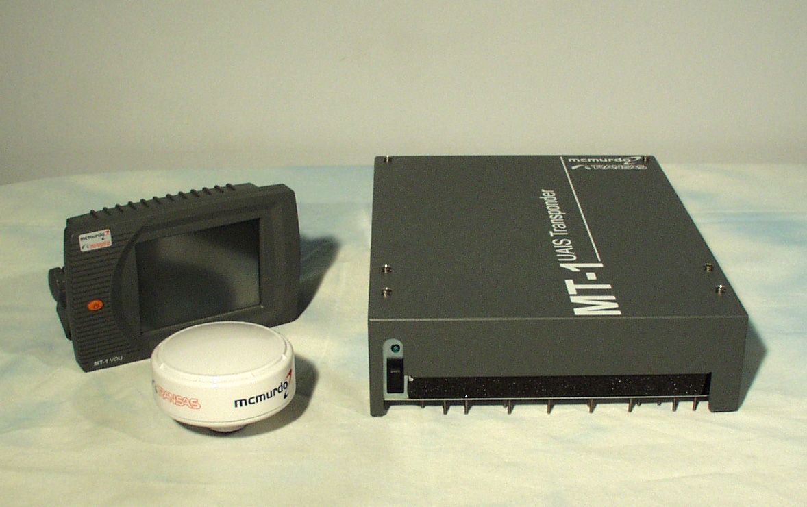
KLS-MT-1McMurdo/Transas MT-1
Orolia Ltd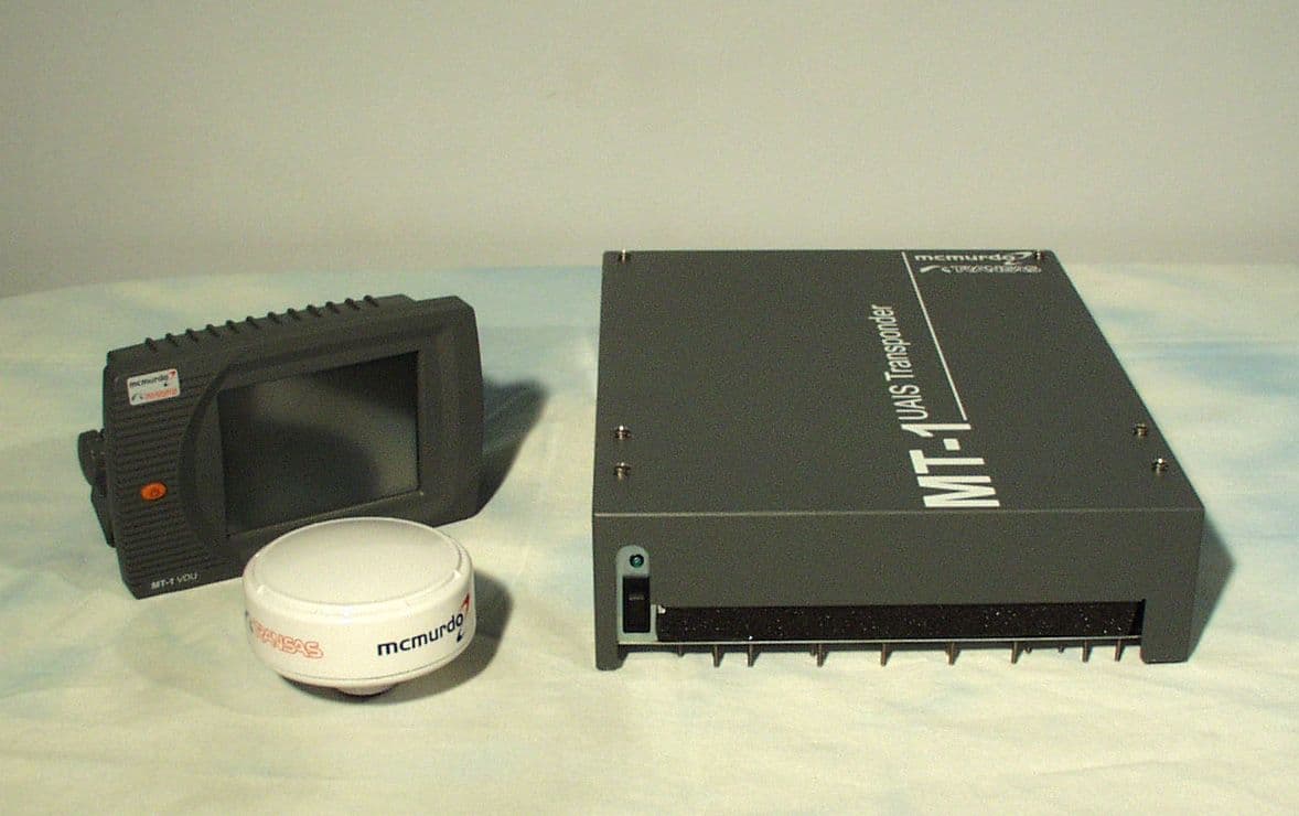
Click to zoom
Application Details
- Equipment Class
- AIS - Automatic Identification Systems
- Date of Grant
- Mar 09, 2004
- Application Purpose
- Original Equipment
- Date of Application
- Jan 20, 2004
- Equipment Note
- McMurdo/Transas MT-1
- Frequency Range
- 156.52500000 - 156.52500000
- Company
- Orolia Ltd
- Country
- United Kingdom
Documents & Files

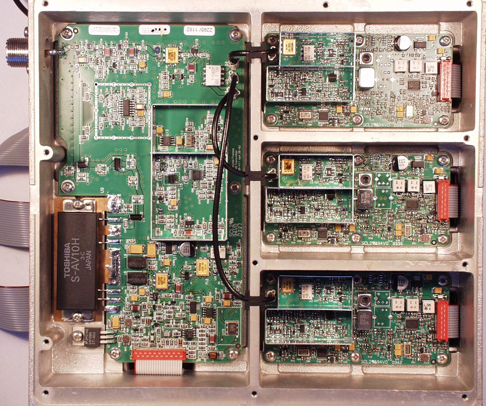
Document Text
Text extracted from the exhibit documents filed with the FCC. Open a document above to read the original.
Users Manual
Installation Manual UAIS Transponder System S4-689-041 Section 4 Issue 5 Method of connecting screens at the transponder Test and program connections WARNING: Do not interfere with switch S1 or the links “Factory Test” and “Program Linker”. These are specialised functions for use by factory technicians only. For the same reason, make no connection to Test Port. Screw Terminal Board S5 S4 S8 S2 S6 S7 89-041 Section 4 Issue 5S4-7 Power supply Connected to the ship’s 24V DC emergency power source through a 2-pole switched fused supply to allow isolation for servicing. The power requirements are 24V DC +30% -10%, 3.5A maximum. Standby power requirement21 W; 0.9 Amp at 24V DC Peak power requirement75 W; 3.5 Amp at 24V DC Required conductor area as a function of cable length Power cable lengthRequired conductor area 0 – 10 metres0.75 mm 2 10 – 20 metres1.5 mm 2 20 – 40 metres3.0 mm 2 Isolation between the power supply connections and any other connection to the transponder is 1kV minimum. The DC power source should comply with IMO guidelines for the class of vessel concerned. National authorities and classification societies may have their own power supply requirements that should also be considered. If the available supply is AC, a converter, P/N 89-029, is available as an option. DISP port - Display VDU The DISP port connects the VDU Display unit with the Transponder. This port is vital to the functionality of the transponder and the VDU and must be connected. To prevent any malfunction of this port it is not possible to change the configuration. Display cable: Four twisted pairs, screened, PVC sheathed. Cable length to displayRequired conductor area 0 – 100 metres0.8 mm 2 each wire 100 metres +1.5 mm 2 each wire The connection between the Screw terminal board and the VDU unit is given below, showing the rear of the VDU and the 15-pin connector, and the pin identification of the connector. TransponderVDU pin Rx common2 Rx B1 Rx A6 Tx A12 Tx B13 Tx common8 + Bat out3 - Bat out4 The twisted pairs are assigned as (Rx A/B), (Tx A/B), (common pair) and (battery pair) The DISPLAY port can be connected to a Personal Computer, but two precautions are necessary: special software is required to display the received information, and usually it is necessary to convert the RS 422 signal from the transponder to a RS-232 signal in order to interface to the PC. S4-889-041 Section 4 Issue 5 SEN 1, 2, 3 ports - Sensors The Sensor input port can be configured to receive data from the Gyro, the GNSS used for navigation and the LOG. Each of the three sensor (SEN1, SEN2 and SEN3) ports can be independently configured to receive information from one of these sensors. Alternatively ALL sensor information can be received via ONE of the sensor ports. The sensor ports require configuration before use; this is described in the Operation Manual. The AIS must be connected to: • The GNSS unit used for navigation • The gyrocompass providing heading information If available the following information can be connected to the AIS: • Rate-Of-Turn (ROT) • Speed over ground from Bottom referenced log Recommended cable for connection of Sensors: Single twisted pair, shielded, PVC sheathed. Cable length to displayRequired dimension 0 – 100 metres0.8 mm 2 each wire Sensor wire connection The twisted pair shall be assigned as RxA and RxB SEN Ports necessary sentences: The basic requirements are: IEC 61162-2 standard ITU-T V.11 electrical properties Speed can be configured from 1200 - 38400 bits/sec Data bits 8, Stop bits 1, Parity none All required as well as optional sentences are listed in the table; ensure that the connected sensor transmits at least the required sentences (as given by IEC 61162): IEC 61162-2 sentence format SensorData RequiredOptional Reference datumDTM Positioning system Time of position Latitude/longitude Position accuracy GNS, GLLGGA, RMC Speed over ground (SOG) VBWVTG, OSD, RMC Course over ground (COG) RMCVTG, OSD RAIM indicatorGBS GNSS Route planRTE, WPL HeadingHDTOSDGYRO Rate of turn (ROT)ROT LOGSpeed over ground (SOG) VBW 89-041 Section 4 Issue 5S4-9 Course over ground (COG) Main and AUX high speed input/output ports The Transponder has two high-speed communication ports. The ports are identical, the same information is input and output on these ports. All information received and transmitted on the VHF link will be reflected as correct IEC 61162 sentences. All error messages will also be transmitted. The Main port will primarily be used to connect external equipment such as ECDIS and ARPA or another navigation information display system. The AUX port will primarily be used for connection to the “pilot plug” - a connector installed on the bridge near the pilot operation position so that the pilot can connect a Personal Pilot Unit, which is normally a laptop computer with the pilot’s navigational software installed. MAIN port Three twisted pairs, shielded, PVC sheathed. Cable length to displayRequired dimension 0 – 100 metres0.8 mm 2 each wire Main port wire connection The twisted pairs shall be assigned as (RxA/RxB), (TxA/TxB) and (RxCom/TxCom). AUX port, Pilot plug Three twisted pairs, shielded, PVC sheathed. Cable length to displayRequired dimension 0 – 100 metres0.8 mm 2 each wire AUX/Pilot port wire connection The twisted pairs shall be assigned as (RxA/RxB), (TxA/TxB) and (RxCom/TxCom) In the IMO installation guide for AIS transponders, the Pilot plug is recommended to be: • AMP/Receptacle (Square Flanged), Shell size 11, 9 pin Std. Sex 206486-1/2 or equivalent and the termination shall be as illustrated in the table. TransponderPilot Plug 1RxCOMNo Connection 2RxBPin 6 3RxAPin 5 4TxAPin 1 5TxBPin 4 6TxCOMNo Connection S4-1089-041 Section 4 Issue 5 LRF port, Long Range Function The AIS Long-Range Function requires a compatible long-range communication system e.g. Inmarsat-C. If this is available, a connection to the Inmarsat-C system can be made. It is required that the Inmarsat-C input/output port can…
Text truncated - open the document above for the full version.
Users Manual
Operation Manual UAIS Transponder System 89-042 Issue 519 3.19 DSC Tuning Menu UAIS can receive and process DSC information sent by Base stations. Periodically lists of geographical regions and their associated parameters are transmitted on the DSC channel. DSC is normally set to Channel 70. Methods of tuning DSC: DSC command from coastal station. Manually from the VDU. 3.20 Long Range Request Menu This feature is only available with a specialised interface to a suitable source. 2089-042 Issue 5 3.21 Other Stations Menu This is the main working menu that displays information on all the received targets. These targets can be viewed in three ways; as a list of vessel names along with Bearing and Distance, more detailed information about individual vessels or as a ‘radar-style’ overview. Individual targets can be viewed in more detail in 2 ways. Highlight a target; at the top of the screen more detailed information can be seen about the selected target. For full details, highlight the target and press Detail Further information on the selected target is produced by selecting More 89-042 Issue 521 Presson the Other Stations menu to view the navigational situation in a “radar-style” format. This screen shows all received AIS stations and their velocity vector. The top left number is the number of stations within the range of the display. The range, shown at top right, corresponds with the outer ring of the displayed graphic. Pressorto change range between 1nm to 100nm in 7 steps. Pressto view or hide text captions (call signs) of the displayed targets. 3.22 Sending messages From the Other Stations menu, short text messages can be sent to specific vessels or groups of vessels. The text is generated using the on-screen keyboard and may be sent to any or all of the indicated targets (which may be shore based stations). From the target list, highlight the intended destination of the message and press 2289-042 Issue 5 The top line of the screen shows the destination call sign and MMSI number. The second line displays the message text and the bottom line shows the AIS channel on which the message is to be sent, A or B. Either may be used. To change the destination of the message, select the To: line and select Change From this screen the MMSi of the recipient vessel may be changed, or a group MMSI may be used, or the message may be broadcast to all ships. OK returns to the previous screen. Highlight the Txt: line and select Change. A keyboard entry screen appears. Enter the test to be transmitted, switching between screens to access different sections of the keyboard. 89-042 Issue 523 When the message has been entered correctly, select OK. Select Send to transmit the message. To test the system, select a coast station and compose a message, for example: - “This is an AIS test call, please acknowledge”. If no acknowledgement is received the message will be re-transmitted up to four times. If no acknowledgement is received after the four transmissions, try another station in the list. 2489-042 Issue 5 3.23 Receiving a message When a message is received and identified as being for the particular vessel (ie it has the correct MMSI number), a screen appears to alert the operator and to display the text. Further details of the message can be viewed by entering the Radio Exchange screen. 3.24 Radio Exchange menu Full details of received messages can be viewed. The received messages are then displayed with time and date of transmission, message text and details of the sender. 89-042 Issue 525 3.25 Alarms & Faults When an alarm condition occurs a pop-up window will appear, eg Pressto acknowledge the alarm message. To clear an alarm and deactivate the BIIT relay, first select Alarms & faults from the Main menu then select Alarm status to view all the alarm conditions. 1289-042 Issue 5 3.9 Dist.GNSS-Bow Dist.GNSS-Stern Dist.GNSS-Port-side Dist.GNSS-Starboard (Default = 0) These values are set up during commissioning. Refer to section 4.15 for further information. 3.10 Type of Cargo (Default = 0) Enter to type of vessel and cargo. Please see the tables below for details (tables are derived from the ITU-1371-1 standard). Identifiers Used by Ships to Report Their Type First DigitSecond Digit 0 - Not used0 - All ships of this type 1 - Reserved for future use1 - Carrying DG, HS, or MP IMO hazard or pollutant category A 2 - WIG ( Wing In Ground )2 - Carrying DG, HS, or MP IMO hazard or pollutant category B 3 – Other ships See table overleaf 3 - Carrying DG, HS, or MP IMO hazard or pollutant category C 4 - HSC ( High Speed Craft )4 - Carrying DG, HS, or MP IMO hazard or pollutant category D 5 – Special craft See table overleaf 5 - Reserved for future use 6 - Passenger Ships6 - Reserved for future use 7 - Cargo Ships7 - Reserved for future use 8 - Tankers8 - Reserved for future use 9 - Other types of Ship9 - No additional information DG = Dangerous Goods HS = Hazardous Substances MP = Marine Pollutants 89-042 Issue 513 Identifiers Used by Other Ships to Report Their Type Identifier Number First Digit Second Digit Vessel Type 30Fishing 31Towing 32Towing and length of the tow exceeds 200mtrs (656ft) or breadth exceeds 25mtrs (82ft) 33Engaged in dredging or underwater operations 34Engaged in diving operations 35Engaged in military operations 36Sailing 37Pleasure craft 38Reserved for future use 39Reserved for future use Identifiers Used by Special Craft to Report Their Type Identifier Number First Digit Second Digit Vessel Type 50Pilot vessel 51Search and rescue vessel 52Tugs 53Port tenders 54Vessels with anti-pollution facilities or equipment 55Law enforcement vessels 56Spare – for assignments to local vessels 57Spare – for assignments to local vessels 58Medical transports (as defined in the 1949 Geneva Conventions and Additional Protocols) 59Ships according to Resolution No. 18 (Mob-83) 1489-042 Issue 5 3.11 Max. Static Draught (Default = 0.0) Enter the maximum static draught of vessel (in metres) during the current vo…
Text truncated - open the document above for the full version.
Users Manual
2689-042 Issue 5 All active alarms will be displayed along with an exclamation mark (!) next to the alarm number. To clear the alarm, select that alarm and press CLEAR, the exclamation mark will disappear. When all alarm conditions have no exclamation mark (!) the BIIT relay will deactivate. 3.26 Show Status Menu These screens relate to the performance of the Transponder. The first screen shows the Purpose (SOLAS ships must show Class A) and the MMSI number. Refer to sections 4.4 and 4.3 for further details. The next screen shows the status and parameters of the internal GNSS 4089-042 Issue 5 4.18 Alarm Signals Menu (Default = On) In this menu, the status of different alarm signals can be viewed and enabled or disabled. The alarm signals will give validity information to the operator in case a fault occurs. Therefore it is recommended to keep all the alarm signals set to ‘On’ which is the default setting. The transponder contains a Built-In-Integrity-Test (BIIT) that continuously monitors the standard functions of the equipment. This relay facility should be connected to the ship’s main alarm panel. If any failure or malfunction is detected that will significantly reduce the integrity or stop operation of the UAIS, a single alarm message is displayed on the VDU touch-screen and the BIIT alarm relay activated. If the alarm status continues the appropriate alarm message is repeated every 30 seconds on both the MAIN and AUX ports for display on other connected equipment. 89-042 Issue 541 Alar m T extSystem Reaction Tx malfunctionStops transmission Antenna VSWR exceeds limitContinues operation Rx channel A malfunctionStops transmission on affected channel Rx channel B malfunctionStops transmission on affected channel Rx channel DSC malfunctionStops transmission on affected channel General failureStops transmission MKD connection lostContinues operation with DTE set to 1 External EPFS lostContinues operation No sensor position in useContinues operation No valid SOG informationContinues operation using default data No valid COG informationContinues operation using default data Heading lost/invalidContinues operation using default data No valid ROT informationContinues operation using default data No TDMA synchronisationStops transmission Tx amplifier malfunctionStops transmission No own reports modeContinues operation 4.19 RS-422 Set-up Menu (Default = On) The RS-422 set-up menu is used to configure the mode of the serial connection to the interface ports. The default parameters can be changed to enable correct communication to or from the external equipment connected to the specific port. Select the port to setup 4289-042 Issue 5 Activate port Select port baud rate Select port parity 89-042 Issue 543 Select port stop bits The table shows the parameters that can be set for each port. RS-422 Set-up Table PortBaud rateParityStop bits Main Aux/Pilot IGNS Long Range RTCM Sen1/2/3 1200 2400 4800 9600 38400 None Odd Even 1 2 4.20 Test Interfaces Allows checking of the interfaces for faults, using external or internal loopback. A more detailed description is given in the Service Manual. 4489-042 Issue 5 4.21 DGNSS Set-up Menu UAIS can transfer differential data corrections via the AIS channels (message 17). Data received via the RTCM input port may be sent to 2 reference stations whose geographical co-ordinates are known and which have been manually set up. If the reference station is transmitting RTCM message 3, it is showing its own co- ordinates that UAIS can store. No more than 4 reference stations can be stored at any one time. 4.22 Engineering Mode Engineering mode option in the Main setup menu is designed for testing and setting up an UAIS at the factory, it is protected by a password known only by authorised personnel. Users must not activate Engineering mode. 4.23 Other Options Other options in the Main set-up menu is designed for setting up an UAIS at the factory; this feature is protected by a password known only by authorised personnel. 89-042 Issue 533 After successful completion of the self-test and communication between the VDU and the transponder has been established the following screen will appear. The welcome screen giving the GNSS type (GPS or GLONASS), software version, and software build date then appears, which confirms that the VDU is ready for operation. Pressto enter the Main Menu. SELECT - Enter set-up from the menu. 3489-042 Issue 5 Pressto stop data transmission. At this point a system password has to be entered. If no previous password has been entered, pressing OK will by-pass this request. A password should be entered to prevent accidental or malicious changing of stored data. THIS PASSWORD SHOULD BE RECORDED IN A SECURE PLACE. WARNING: It is not possible to access Main Setup without entering the correct password. Only authorised service personnel can restore access. 4.2 Main Set-up Menu 89-042 Issue 535 4.3 General Set-up Menu The General set-up menu allows the following parameters to be set up: - 4.4 MMSI The Maritime Mobile Service Identity (MMSI) number must be entered. 4.5 Purpose Select purpose of the UAIS station. (SOLAS ships must be set to Ship class A) 3689-042 Issue 5 4.6 IMO Number The assigned ship’s IMO number has to be entered. 4.7 RAIM Present (Automatically selected) The station will automatically check for RAIM presence in working mode – by $-- GBS sentences on Sens1, Sens2 or Sens3 inputs. The operator can manually override the automatic selection by highlighting the RAIM line and selecting Change. In normal circumstances this function is not used. 4.8 Setup System Password For safety reasons some data is protected by a system password (maximum 8 characters). When the system is initially switched on, no password exists. Pressing OK allows the user to enter the desired password. We strongly recommend that during commissioning a password is entered to prevent the transmitted data from being erased or amended either accidentally or maliciously. A record…
Text truncated - open the document above for the full version.
Users Manual
89-042 Issue 545 4.24 Log File This log file is detailed in section 3.31 4.25 Saving Changes If any changes have been made to the settings, UAIS will ask for confirmation of those changes. To complete the process the correct password will need to be entered. PRESSto exit and return to Main menu. This action returns UAIS to normal transmission. 89-042 Issue 547 5 Maintenance and Servicing 5.1 Preventative Maintenance The UAIS transponder system is an essential part of the ship’s navigation system and is a vital component for the safety of the ship and its crew. It is therefore very important to maintain the system and its installation to a very high standard. The design of the UAIS transponder ensures that maintenance can be kept to a minimum, however it is good practice to perform a performance check at least once every week. 5.2 VDU Touch-Screen To optimise performance of the touch-screen VDU and cabinet, ensure they are kept clean and grease-free. Use a clean damp cloth, or for heavier deposits use a clean, damp cloth and a mild solution of dish washing detergent and water. Do not use any spirit or alcohol based solvents, gasoline or oils. 5.3 Electrical Connections Periodically check the electrical connections; ensure that no cables are frayed or worn, and that all connections are tight and sound. 5.4 Repair and Service With the exception of the fuses located on the Screw Terminal Board, there are no user serviceable parts. Changing fuses is described in Section 6 – Troubleshooting. Removal of the inspection plates other than by an Authorised Service Technician will void warranty. If having followed the Troubleshooting Guide (Section 6) UAIS is still inoperable, please call your local Service Centre. 5.5 Spare Parts Use only manufacturers genuine spare parts. No liability can be accepted for equipment failure due to incorrect replacement parts being used. 5.6 World-wide Sales and Service For a complete list of worldwide sales and service agents, please contact your product supplier. 89-042 Issue 549 6 Troubleshooting Perform the following checks BEFORE calling an authorised Service Centre. SymptomCauseCure 1) No power to Transponder 2) System fuse blown No Green light illuminated on Transponder 1) Check fuse or circuit breaker at 24VDC supply point. 2) Check/replace system fuse in Transponder. Use only 10Amp blade type fuse No text on screen 1) VDU installation 2) Display fuse blown Green light is illuminated on Transponder 1) Check display cable/connections 2) Check display fuse in Transponder. Use only 1Amp blade type fuse Text appears on screen but is too dark or light to read LCD backlight and/or contrast out of adjustment 1) Select Display Brightness from Main menu 2) Adjust LCD backlight and/or contrast (See section 3.36 Display Brightness Menu on page 29) At power-up, self-test shows one of the following messages: - ROM : Error RAM : Error FLASH : Error Central processor failure Contact Service Centre Tx malfunction alarm activates Transmitter PCB failure Contact Service Centre 5089-042 Issue 5 SymptomCauseCure Antenna VSWR exceeds limit alarm activates Antenna installation1) Check cable/connections 2) Check antenna Rx channel A malfunction alarm activates Receiver PCB failureContact Service Centre Rx channel B malfunction alarm activates Receiver PCB failureContact Service Centre Rx channel DSC malfunction alarm activates Receiver PCB failureContact Service Centre General failure alarm activates 1) No power to Transponder 2) System fuse blown No Green light illuminated on Transponder 1) Check fuse or circuit breaker at 24VDC supply point. 2) Check/replace system fuse in Transponder. Use only 10A blade type fuse MKD connection lost alarm activates VDU installationCheck display cable/connections External EPFS lost alarm activates GPS signal lost1) Check GPS 2) Check cable/connections No sensor position in use alarm activates GPS installation1) Check cable/connections 2) Check GPS 3) Enable internal GPS to provide position (See section 4.15 Intern. GNSS Position on page 38) No valid SOG information alarm activates 1) Bottom Track Log signal lost 2) GPS signal lost 1) Check GPS 2) Check cable/connections 89-042 Issue 551 SymptomCauseCure No valid COG information alarm activates GPS signal lost1) Check GPS 2) Check cable/connections Heading lost/invalid alarm activates 1) Gyro compass 2) Gyro interface 3) Connection between Transponder and Gyro / interface 1) Check Gyro or Interface Unit 2) Check cable/connections No valid ROT information alarm activates 1) Gyro compass 2) Gyro interface 3) Connection between Transponder and Gyro / interface 3) Check Gyro or Interface Unit 4) Check cable/connections No TDMA synchronisation alarm activates Integral GPS signal lost1) Check cable/connections 2) Check antenna Tx amplifier malfunction alarm activates Transmitter PCB failureContact Service Centre No own reports mode alarm activates Purpose of station set to No own reports mode Re-assign purpose of station (see section 4.5 Purpose on page 35) Changing a fuse There are two fuses, located on the Screw Terminal Board, which are designed to be changed by the user. These are the only user servicable parts. Fuse descriptionFuse valuePart No. Main system fuse10.0 Amp99-077 VDU system fuse1.0 Amp99-076 Switch off the Transponder, undo the six screws retaining the cover, then lift off the cover. Ensure that the power is off before attempting to remove a fuse. The fuse link is visible through the transparent body of the fuse. Ensure that the fuses are not interchanged. The values are clearly marked on the board. When the fuses have been checked to be intact, replace the cover, fit the six screws and tighten carefully. 89-042 Issue 553 7 Specification General Data Power consumption:75W Power supply:24 VDC –10% +30% AIS1 (CH87B)161.975 MHz AIS2 (CH88B)162.025 MHz Default frequencies: DSC (CH70)156.525 MHz Operating temperature: -15°C to +55°C Storage temperature: -20°C to +70°C Environmental:As per I…
Text truncated - open the document above for the full version.
Attestation Statements
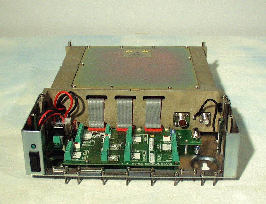
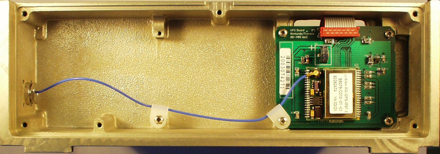
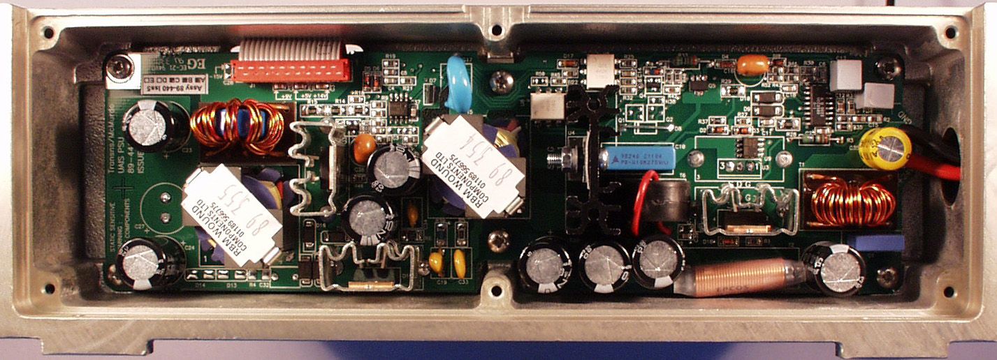
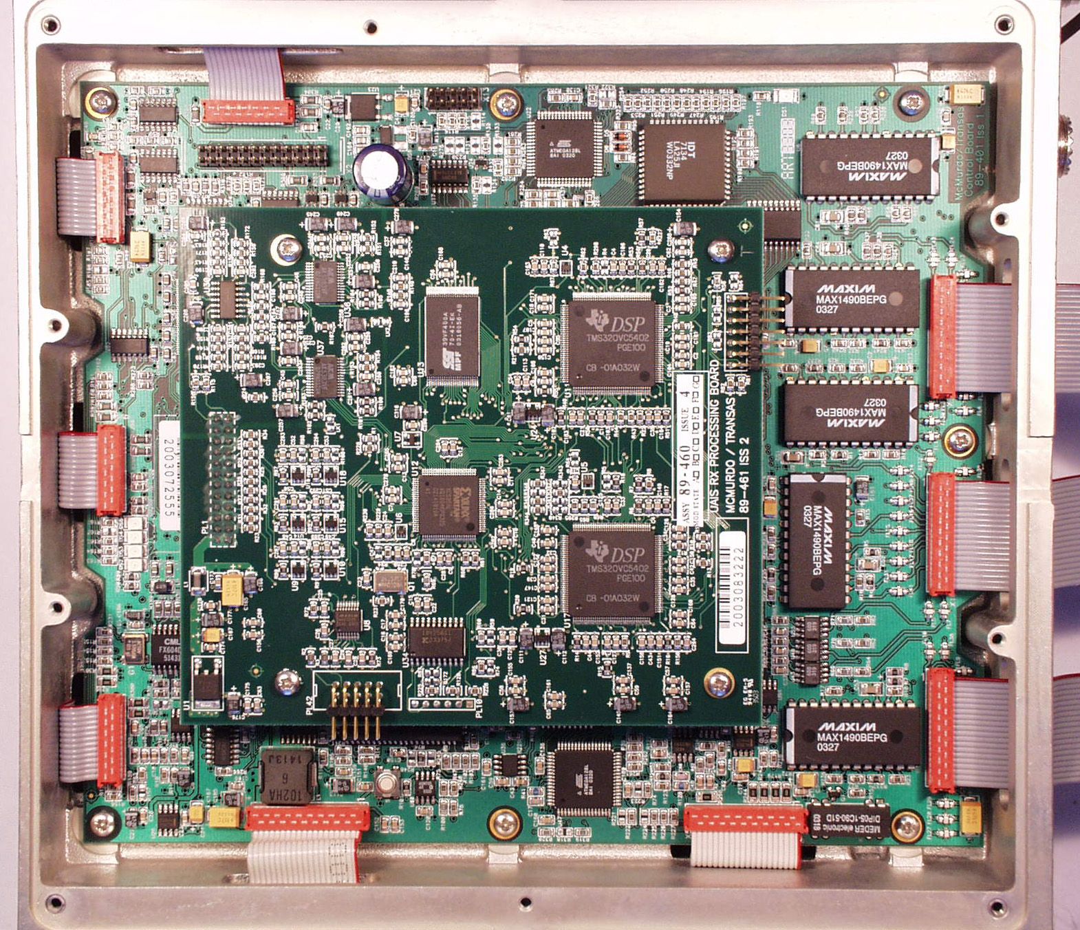
UAIS Type Approval Submission – List of Exhibits for FCC Exhibit typeFile Size DescriptionConfidential Exhibit List (this document) 13KList of ExhibitsNo Attestation Statements 139KEC Quality System (Module D)No 186KEC Type Examination (Module B)No 43KFCC 47CFR80.373 StatementNo 95KUSA (USCG) MT-1 AIS CertificateNo 51KUSA (USCG) MT-1 AIS LetterNo Block Diagrams948KSystem Wiring Diagram 89-043N lssue 3No 73KOperating Menu Hierarchy 89-046N Issue 1No 46KSystem Block DiagramNo ID Labels35KApproval Label 89-376No 52KID Label Display 89-131-001DNo 61KID Label Transponder 89-349-001DNo User’s Manuals2990KUAIS Installation Manual 89-041N Issue 5No 2820KUAIS Operation Manual 89-042N lssue 5 Section 1No 2690KUAIS Operation Manual 89-042N lssue 5 Section 2No 954KUAIS Operation Manual 89-042N lssue 5 Section 3No Parts Lists88KControl Board Assy BOM (4 pages) 89-400L Yes 74KDisplay PCB Assy BOM (3 pages) 89-200L Yes 81KDSC Receiver BOM (4 pages) 89-425L Yes 61KGPS Receiving Board BOM (2 pages) 89-465L Yes 74KPSU PCB Assy BOM (3 pages) 89-440L Yes 70KRx Processor Board Ass BOM (2 pages) 89-460L Yes 65KScrew Terminal Board BOM (2 pages) 89-430L Yes 81KTDMA Receiver BOM (4 pages) 89-420L Yes 87KTransmitter Board BOM (4 pages) 89-410L Yes Photos: External290K3 Units: Transponder, Display & AntennaNo 283KAntenna ID Label View UnderneathNo 130KDisplay ID Label Rear ViewNo 91KTransponder ID Label, Case Top Side ViewNo Photos: Internal338KTransponder, Cover removedNo 333KTransponder, GPS InterfaceNo 340KTransponder, PSUNo 991KTransponder, Control & Rx ProcessingNo 934KTransponder, Transmitter & ReceiversNo Schematics721KControl Board (8 pages) 89-400C Yes 119KDisplay Board (2 pages) 89-200C Yes 42KGPS Receiver Board 89-465C Yes 156KPSU (4 pages) 89-440C Yes 59KTDMA/DSC Receiver 89-420C Yes 311KRx Processor (4 pages) 89-460C Yes 162KScrew Terminal Board (3 pages) 89-430C Yes 169KTransmitter (3 pages) 89-410C Yes Operational Description 1730KUAIS Technical Overview Yes ...continued Exhibit typeFile Size DescriptionConfidential Test Report2250KBSH: 734.2/0046/2003-S3220 03-11-2003 Yes 2880KTelefication Test Report: 99367921 Yes 2630KTelefication Radio Test Report: 99367931 Part 1 Yes 1480KTelefication Radio Test Report: 99367931 Part 2 Yes All files are Adobe Acrobat .PDF format except for photos which are JPEG graphic format WARNING: Where the Confidential column indicates Yes, the document is McMurdo copyright and contains proprietary owned intellectual property rights and confidential data. All rights are strictly reserved. The information must be used only for the agreed purpose. Unauthorised use, reproduction or issue to any third party is not permitted without the prior written agreement of McMurdo Limited.
Block Diagram
AUX SWITCH Terminating resistor. ONLY switch-on if last device in chain LONG RANGE PORT Cable: 3 Twisted Pair + Drain Class A Ship-borne UAIS Wiring Diagram DISPLAY ( VDU ) PORT Cable: 4 Twisted Pair +Drain SEN1, SEN2 & SEN3 ( Gyro / GNSS / BT Log ) Cable: 1 Twisted Pair + Drain Cable Colour / No. Device Assignment 1 RXCOM No Connection 2 RXB 3 RXA 4 TXA 5 TXB 6 TXCOM No Connection Transponder Cable Colour / No. Device Assignment 1 RXCOM No Connection 2 RXB 3 RXA 4 TXA 5 TXB 6 TXCOM No Connection Transponder Cable Colour / No. Display Connector Assignment 1 RXCOM Pin 2 2 RXB Pin 1 3 RXA Pin 6 4 TXA Pin 12 5 TXB Pin 13 6 TXCOM Pin 8 7 SPARE 8 +BATOUT Pin 3 9 -BATOUT Pin 4 Transponder PWR-OUT (Power out to Chassis) SYSTEM FUSE (10 AMP ) DISPLAY FUSE (1 AMP ) PWR-IN (Power supply input) Double pole switch fused 10A supply Transponder Cable Colour / No. Bus Bar + BAT IN 24VDC - BAT IN 0VDC AUX / PILOT PORT Cable: 3 Twisted Pair + Drain Cable Colour / No. Pilot Plug Assignment 1 RXCOM No Connection 2 RXB Pin 6 3 RXA Pin 5 4 TXA Pin 1 5 TXB Pin 4 6 TXCOM No Connection Transponder RTCM PORT (Differential correction) Cable: 3 Twisted Pair + Drain Cable Colour / No. Device Assignment 1 RXCOM No Connection 2 RXB 3 RXA 4 TXA 5 TXB 6 TXCOM No Connection Transponder Cable Colour / No. Alarm Panel Assignment 1 N/C 2 N/O 3 COM 4 SPARE Transponder TEST / PROGRAMMING SWITCH (Normal / PC Change Over) Authorised Service Personnel Use ONLY. Ensure switch is in the NORMAL position TEST / PROGRAMMING PORT Authorised Service Personnel Use ONLY MAIN / RTCM SWITCH Terminating resistor. ONLY switch-on if last device in chain Cable Colour / No. Sensor Assignment 1 SEN1-RXB 2 SEN1-RXA 3 SEN1-COM No Connection 1 SEN2-RXB 2 SEN2-RXA 3 SEN2-COM No Connection 1 SEN3-RXB 2 SEN3-RXA 3 SEN3-COM No Connection Transponder SEN1 / SEN2 / SEN3 SWITCHES Terminating resistor. ONLY switch-on if la st device in chain DISP/LR SWITCH Terminating resistor. ONLY switch-on if last device in chain VHF Antenna PL259 or N Connector PL259 Transponder GPS Antenna TNC Connector TNC Connector Transponder NOTES: 1) Twisted wire MUST be paired as (RXA / RXB), (TXA / TXB). 2) Drain wires MUST be terminated with screen under cable cleats. 3) Transponder chassis MUST be connected to ships ground. N/C Com N/O MAIN PORT ( ECDIS / ARPA ) Cable: 3 Twisted Pair + Drain RELAY (BIIT) PORT Cable: 1 Twisted Pair + Drain 89-043N Iss3 UAIS Wiring Diagram
Block Diagram
UAIS Operation Menu Hierarchy No link with main unit Check ROM, RAM, FLASH, Starting.... AIS Transponder Manufacturers Brand(s)Date/UTC Lat Lon Pos SOG COG HDG ROT RAIM Call SignEnter Data NameEnter DataEnter Password Dist. GNSS-Bow Enter Data (0) Dist. GNSS-Stern Enter Data (0) Dist. GNSS-Port-side Enter Data (0) Dist. GNSS-Starboard Enter Data (0) Type of Cargo Enter Data (0) Max Static Draught Enter Data (0.0) Persons on Board Enter Data (0) DestinationEnter Data ETA (time) Enter Data (24:60) ETA (date) Enter Data (00-00) Undefined Under Way (Engine) At Anchor Not Under Command Restr. Manoeuvrability Contr. By Draught Moored Aground Engaged in Fishing Under Way (Sailing) Display Present Yes / No Mode of tuningThis AreaMode of tuningIn Area Channel AEnter DataChannel AEnter Data Bandwidth A 25 / 12.5 Bandwidth A25 / 12.5 …
Text truncated - open the document above for the full version.
Contact Information
Applicant
Erwan Thomas(Certification and hardware engineer)
Technical Contact
Technical Specifications
| # | Rule Parts | Frequency Range | Power Output | Emission | Tolerance |
|---|---|---|---|---|---|
| 3 | 8 | 156.525 MHz - 156.525 MHz | 12.5 W | 14K2G2B | 1000 Hz |
Other Applications from Orolia Ltd

KLS-Z502
Apr 19, 2012AIS-MSLD
Equipment Class
AIS - Automatic Identification Systems
KLS-Z501
Apr 19, 2012AIS-MSLD
Equipment Class
AIS - Automatic Identification Systems
KLS-G5-2
Jul 10, 2011McMurdo Smartfind Plus G5, Sailor SGE406-II, Simrad EG50
Equipment Class
GEP - 406 MHz EPIRB
KLS-E5-2
Jul 10, 2011McMurdo Smartfind E5, Kannad Marine Automatic EPIRB, Kannad Marine Manual EPIRB, Sailor SE406-II, Simrad EP50
Equipment Class
GEP - 406 MHz EPIRB
KLS-PLB-4-GPS
Apr 05, 2011Fastfind MaxG, Safelink Pro, XS-ER GPS
Equipment Class
PLB - Personal Locator Beacons