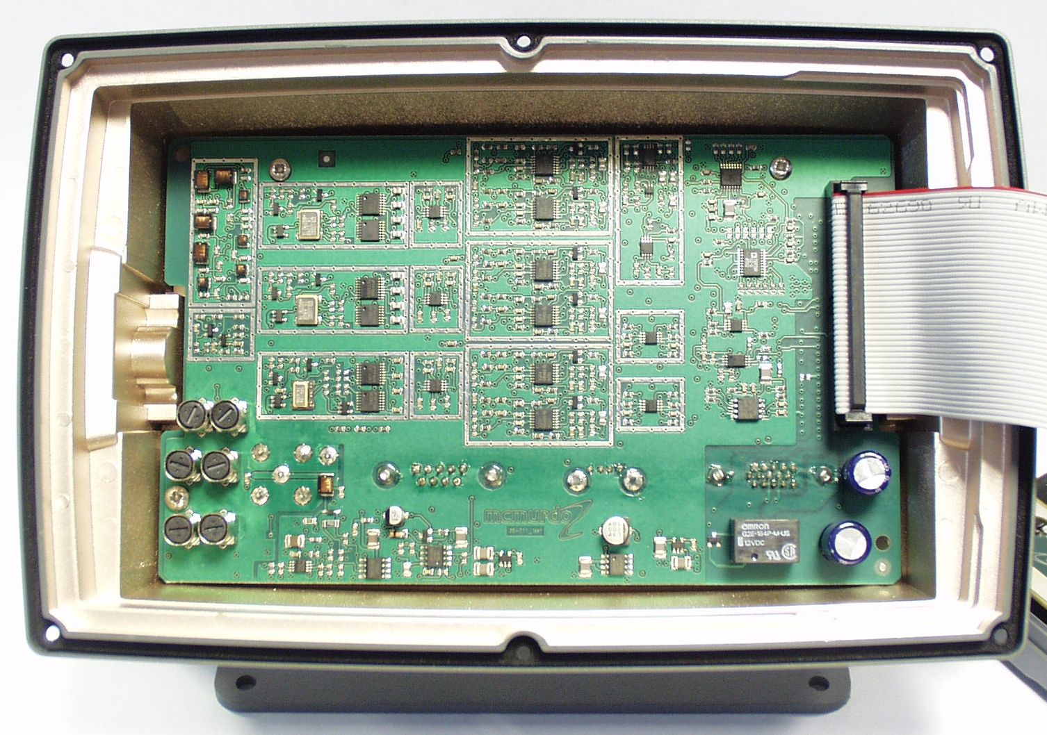
KLS-NAV-7NAVTEX Receiver
Orolia Ltd
Click to zoom
Application Details
- Equipment Class
- RNV - Part 80 NAVTEX Receiver
- Date of Grant
- Oct 22, 2006
- Application Purpose
- Original Equipment
- Date of Application
- Aug 02, 2006
- Equipment Note
- NAVTEX Receiver
- Frequency Range
- 4.20950000 - 4.20950000
- Company
- Orolia Ltd
- Country
- United Kingdom
Documents & Files
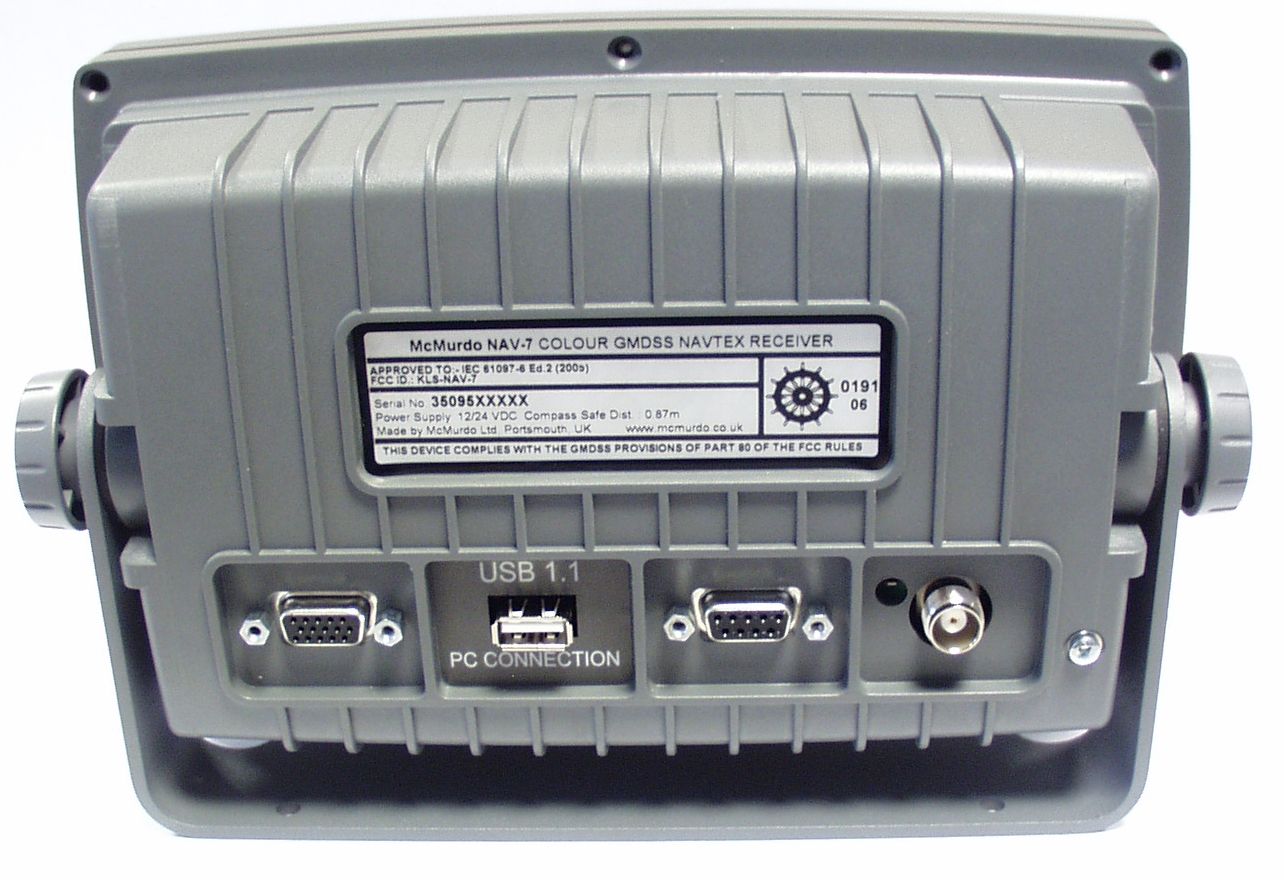
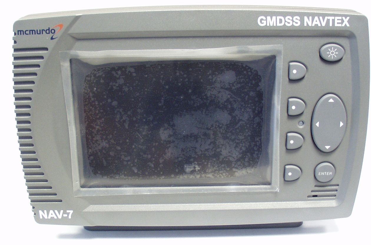
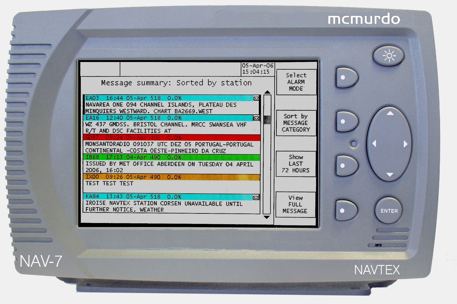
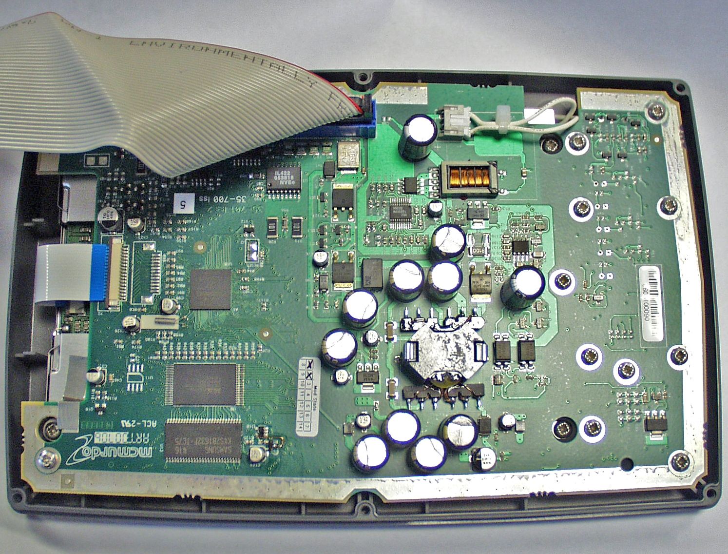
Document Text
Text extracted from the exhibit documents filed with the FCC. Open a document above to read the original.
Users Manual
NAV-7 GMDSS Tri-channel NAVTEX Receiver User & Installation Manual mcmurdo VESSEL IDENTIFICATION INFORMATION Name Call Sign MMSI NAV-7 S/N Antenna Type 518 kHz 490 kHz RX frequencies supported by antenna 4209.5 kHz The technical data, information and illustrations contained in this publication were to the best of our knowledge correct at the time of going to print. We reserve the right to change specifications, equipment, installation and maintenance instructions without notice as part of our policy of continuous product development and improvement. No part of this publication may be reproduced, stored in a retrieval system or transmitted in any form, electronic or otherwise without permission in writing from McMurdo Limited. No liability can be accepted for any inaccuracies or omissions in the publication, although every care has been taken to make it as complete and accurate as possible. Safety Warnings This instrument is for use as an aid to sailors and should not lead to a reduction in the level of good seamanship required at all times. Reception of messages cannot always be guaranteed as this depends on local radio propagation. Contents QUICK START..........................................................................................1 INTRODUCTION......................................................................................2 ABOUT YOUR NAV-7...............................................................................3 OPERATING THE NAV-7.........................................................................4 Navigating the NAV-7 user interface.....................................................................5 Icons...................................................................................................................6 Receiving NAVTEX messages.............................................................................6 Alarms.................................................................................................................7 Finding and viewing NAVTEX messages..............................................................7 Message displays................................................................................................8 Message index display.........................................................................................8 Message index display.........................................................................................9 Message summary display...................................................................................9 Full message display...........................................................................................9 Minimising the number of NAVTEX messages displayed......................................10 Separate frequency channel pages.....................................................................10 Station filtering....................................................................................................10 Message category filtering..................................................................................10 Time-limited display of messages........................................................................10 SETUP...................................................................................................11 Understanding NAVTEX message headers.........................................................11 Colour coding of NAVTEX message headers.......................................................12 Message filters...................................................................................................12 Setup mode: Receiver options.............................................................................13 Using Setup mode: Receiver options screen........................................................14 Setup mode: system options...............................................................................15 Setup mode: serial options..................................................................................16 SYSTEM ALARMS.................................................................................17 SIGNAL MONITOR.................................................................................17 LCD SETUP...........................................................................................18 LCD setup day & night modes.............................................................................18 SERIAL INTERFACES............................................................................19 Connecting a Printer...........................................................................................19 DISPLAY PHYSICAL INSTALLATION....................................................20 NAV-7 system overview......................................................................................20 Trunnion mounting the display.............................................................................20 Trunnion mounting the display.............................................................................21 Flush mounting the display..................................................................................22 DISPLAY ELECTRICAL INSTALLATION................................................24 Ship’s earth connection.......................................................................................24 12V or 24 V DC power connection.......................................................................25 Signal cable connections....................................................................................25 Signal line termination.........................................................................................26 Connecting to the IBS serial interface..................................................................26 Connecting to the NMEA 0183 interface..............................................................27 Alarm relay..........................................................................…
Text truncated - open the document above for the full version.
Users Manual
23 Warning: Do not mount the NAV-7 in a position where sea spray can reach it, or where it may be exposed to direct sunlight 24 DISPLAY ELECTRICAL INSTALLATION This manual is concerned only with the installation of the NAV-7 and does not cover the installation of any peripheral equipment connected to the NAV-7 such as printers, navigational systems or source of NMEA data. For proper installation and connection of peripheral equipment to the NAV-7 refer to the installation manuals for these products. The table below shows the connections that must be made to the NAV-7 for it to function correctly. Connection Must connect Optional Ship’s earth connection ̧ 12V or 24 V DC power supply ̧ NAVTEX antenna ̧ Alarm Relay ̧ NMEA or IBS time reference See Note 1 See Note 1 Integrated Bridge/Navigation System ̧ External printer ̧ Note 1: Connecting a time reference (eg a GPS receiver) is highly recommended. Ship’s earth connection The earth terminal on the rear of the NAV-7 display must be connected to ship’s ground by the earth cable supplied. The earth connection should be kept as short as possible. Safety Warning To ensure the best possible protection of the NAV-7 from static electricity or nearby lighting strikes, the pre-fitted green grounding wire (connected to the safety earth spade) must be connected to a nearby (hull) electrical grounding point. 25 12V or 24 V DC power connection A connection must be made to a 12 or 24 V DC supply via a circuit breaker capable of supplying at least 2 amps. Connection should be to the ship’s radio battery and be in accordance with GMDSS requirements. • Connections should be made using the 2 m power cable provided • Use cable ties to restrain the wiring, and so prevent it becoming weakened by vibration. The connecting cables should be restrained by securing them to the rear of the NAV-7 bracket, or to adjacent metalwork • The screen of the cable should be connected to ship’s earth if possible. The screen of the cable should not be connected to ship’s battery –ve Safety Warning The NAV-7 has been designed and manufactured to be completely safe when used in accordance with the instructions given in this manual. To ensure that the complete installation is safe, it is essential that a fuse or circuit breaker is installed in the power supply cable as described in the Installation section of this manual. Isolation between the power supply connections and any other connection to the NAV-7 is 1 kV minimum. The DC power source should comply with IMO guidelines for the class of vessel concerned. National authorities and classification societies may have their own power supply requirements; these should also be considered. Signal cable connections As shown in the table above, the NAV-7 may be connected to different types of peripheral units including IBS & INS serial ports and printers. The signal connections are all connected via a serial RS422 type interface; data rates are selectable at 4800, 38400 or 115200 baud. In some cases, particularly in retrofit installations, it may not be possible to connect the NAV-7 directly to the required source/destination for serial data, because some equipment does not provide the IEC 61162-2 (NMEA) sentences required by the NAV-7 unit. In such cases a protocol converter is required between the sensor and the NAV-7. Converters are available from different manufacturers, either as direct protocol converters or frequently as repeater instruments for the sensor. 26 15 6 1115 10 Signal line termination RS422 signal lines may need termination resistors at the far end of the serial cable connected to the NAV-7, depending on the length of connecting cable and the rate of data transmission. Both the IBS and the NMEA ports in the NAV-7 have inbuilt 100O termination resistors for both Tx and Rx. Whether termination is required depends on many factors, particularly the length of the signal cable and the environment in which the equipment is operating. The principle is shown in the sketch: There is only one talker per twisted pair; there can be several listeners. The intention is that terminations must be provided by the devices at the ends of the line, regardless of whether they are listeners or the talker, and that no other device should provide a termination. Since the NAV-7 contains internal termination, it MUST be at the end of the line and NOT in the middle. It is good practice to use screened cables in all ship cable installations. Take care to connect the cable screen to ship’s ground at one end only of the cable, as connecting at both ends may cause ground loops and interference to the signals. The cable screen should not be connected to any part of the NAV-7. Connecting to the IBS serial interface The display connection cable is supplied ready for use, and needs only to be plugged into the appropriate connector on the NAV-7. Display cable: Six twisted pairs, screened, PVC sheathed. For lengths to 200 meters, use 0.22 mm 2 (7/32); Belden 8106 or equivalent. The connections to the15-pin socket on the NAV-7 are given below. Note that the cable screen should not be connected to any part of the NAV-7. Talker (NAV-7) Listener (may need termination) Ground cable screen at NAV-7 ONLY Terminating resistor 27 15 6 9 Power, Alarm & IBS port (2m cable supplied) Pin Number Connection NAV-7 Cable Colour Notes 1 IBS_TXA O/P WHITE/BLUE O/P to IBS port 2 3 +V (12/24 V DC nominal) I/P RED/BLUE Ship’s supply +ve 4 -V (0V) I/P BLUE/RED Ship’s supply -ve 5 6 IBS_TXB O/P BLUE/WHITE O/P to IBS port 7 8 AUX_NC O/P ORANGE/WHITE Alarm Relay NC 9 AUX_NO O/P WHITE/BROWN Alarm Relay NO 10 AUX_COM O/P WHITE/GREY Alarm Relay COM 11 12 IBS_RXB I/P GREEN/WHITE I/P from IBS port 13 IBS_RXA I/P WHITE/GREEN I/P from IBS port 14 15 Connecting to the NMEA 0183 interface If a connection to NMEA 0183 compatible equipment is required then a suitable cable has to be purchased or manufactured. Recommended NMEA 0183 cable: Two twisted pairs, screened, PVC sheathed. For lengths t…
Text truncated - open the document above for the full version.
Attestation Statements
TUV Product Service, Octagon House, Concorde Way, Segensworth North, Fareham, Hampshire, United Kingdom, PO15 5RL Tel: +44(0)1489 558100. Website: www.tuvps.co.uk TEST HOUSE CERTIFICATE ©2006 Not to be reproduced, except in its entirety, without the permission of TUV Product Service Page 1 of 1 CLIENT: McMurdo Limited CERTIFICATE NUMBER OO614796/01 Issue 1 Silver Point Airport Service Road PROJECT NUMBER OS614796 Portsmouth PO3 5PB CLIENT’S ORDER NUMBER PO0001907 DATE OF RECEIPT 21 December 2005 TEST ITEM(S) NAVTEX Receiver NUMBER OF ITEMS TESTED 1 SERIAL NUMBER(S) 007 MODEL / PART NUMBER(S) NAV-7 TEST SPECIFICATION / ISSUE IEC 60945 Issue 2002-08 DATE OF TEST 5 January 2006 SYSTEM CONFIGURATION EUT un-powered and powered TEST(S) APPLIED IAW IEC 60945 clause 11.2 – Compass Safe Distance Test 1: In the magnetic condition in which it was received (un-powered). Test 2: After normalising within a Helmholtz Coil (un-powered) Test 3: Powered and operational RESULT(S) OF TEST Approved by . . . . . . . . . . . . . . . . . . . . . . . . . . . Date 15 th March 2006 K W Adsetts Authorised Signatory Distance (mm) From Compass for 0.3 ̊ deflection Orientation Test 1 Test 2 Test 3 Front 470 360 460 Left Hand Side 430 340 360 Right Hand Side 380 370 400 Rear 410 360 270 Top 700 490 630 Bottom 750 870 650 Distance (mm) From Compass for 1 ̊ deflection Orientation Test 1 Test 2 Test 3 Front 300 250 290 Left Hand Side 300 230 270 Right Hand Side 220 230 240 Rear 230 230 230 Top 450 340 370 Bottom 470 520 410
Attestation Statements
TUV Product Service, Octagon House, Concorde Way, Segensworth North, Fareham, Hampshire, United Kingdom, PO15 5RL Tel: +44(0)1489 558100. Website: www.tuvps.co.uk TEST HOUSE CERTIFICATE ©2006 Not to be reproduced, except in its entirety, without the permission of TUV Product Service Page 1 of 1 CLIENT: McMurdo Limited CERTIFICATE NUMBER SX614796/01 Issue 1 Silverpoint Airport Service Road PROJECT NUMBER SX614796/RB Hilsea Hampshire CLIENT’S ORDER NUMBER PO0001906 PO3 5BP DATE OF RECEIPT 13 December 2005 TEST ITEM(S) NAVTEX Receiver NUMBER OF ITEMS TESTED 1 SERIAL NUMBER(S) 007 MODEL / PART NUMBER(S) NAV-7 TEST SPECIFICATION / ISSUE IEC 60945 Issue 2002-08 DATE OF TEST 13 December to 14 December 2005 SYSTEM CONFIGURATION Operating with a representative RF input of -107dBm TEST(S) APPLIED IAW IEC 60945 Clause 8.2.2 – Dry Heat, Functional +55 ̊C for 16 hours RESULT(S) OF TEST The unit remained operational throughout the test. On completion of the test all three receiver inputs (490 kHz, 518 kHz and 4209.5 kHz) were checked with no noticeable deterioration to the performance. Approved by . . . . . . . . . . . . . . . . . . . . . . . . . . . Date 15 th March 2006 I Veal Authorised Signatory
Attestation Statements
TUV Product Service, Octagon House, Concorde Way, Segensworth North, Fareham, Hampshire, United Kingdom, PO15 5RL Tel: +44(0)1489 558100. Website: www.tuvps.co.uk TEST HOUSE CERTIFICATE ©2006 Not to be reproduced, except in its entirety, without the permission of TUV Product Service Page 1 of 1 CLIENT: McMurdo Limited CERTIFICATE NUMBER SX614796/02 Issue 1 Silverpoint Airport Service Road PROJECT NUMBER SX614796/RB Hilsea Hampshire CLIENT’S ORDER NUMBER PO0001906 PO3 5BP DATE OF RECEIPT 13 December 2005 TEST ITEM(S) NAVTEX Receiver NUMBER OF ITEMS TESTED 1 SERIAL NUMBER(S) 007 MODEL / PART NUMBER(S) NAV-7 TEST SPECIFICATION / ISSUE IEC 60945 Issue 2002-08 DATE OF TEST 16 December to 17 December 2005 SYSTEM CONFIGURATION Operating with a representative RF input of -107dBm TEST(S) APPLIED IAW IEC 60945 Clause 8.3.1 – Damp Heat, Functional +40 ̊C, 93% RH for 16 hours RESULT(S) OF TEST The unit remained operational throughout the test. On completion of the test all three receiver inputs (490 kHz, 518 kHz and 4209.5 kHz) were checked with no noticeable deterioration to the performance. Approved by . . . . . . . . . . . . . . . . . . . . . . . . . . . Date 15 th March 2006 I Veal Authorised Signatory
Attestation Statements
TUV Product Service, Octagon House, Concorde Way, Segensworth North, Fareham, Hampshire, United Kingdom, PO15 5RL Tel: +44(0)1489 558100. Website: www.tuvps.co.uk TEST HOUSE CERTIFICATE ©2006 Not to be reproduced, except in its entirety, without the permission of TUV Product Service Page 1 of 1 CLIENT: McMurdo Limited CERTIFICATE NUMBER SX614796/03 Issue 1 Silverpoint Airport Service Road PROJECT NUMBER SX614796/RB Hilsea Hampshire CLIENT’S ORDER NUMBER PO0001906 PO3 5BP DATE OF RECEIPT 13 December 2005 TEST ITEM(S) NAVTEX Receiver NUMBER OF ITEMS TESTED 1 SERIAL NUMBER(S) 007 MODEL / PART NUMBER(S) NAV-7 TEST SPECIFICATION / ISSUE IEC 60945 Issue 2002-08 DATE OF TEST 14 December to 15 December 2005 SYSTEM CONFIGURATION Operating with a representative RF input of -107dBm TEST(S) APPLIED IAW IEC 60945 Clause 8.4 – Low Temperature, Operational -15 ̊C for 16 hours RESULT(S) OF TEST The unit remained operational throughout the test. On completion of the test all three receiver inputs (490 kHz, 518 kHz and 4209.5 kHz) were checked with no noticeable deterioration to the performance. Approved by . . . . . . . . . . . . . . . . . . . . . . . . . . . Date 15 th March 2006 I Veal Authorised Signatory
Attestation Statements
TUV Product Service, Octagon House, Concorde Way, Segensworth North, Fareham, Hampshire, United Kingdom, PO15 5RL Tel: +44(0)1489 558100. Website: www.tuvps.co.uk TEST HOUSE CERTIFICATE ©2006 Not to be reproduced, except in its entirety, without the permission of TUV Product Service Page 1 of 1 CLIENT: McMurdo Limited CERTIFICATE NUMBER SX614796/04 Issue 1 Silverpoint Airport Service Road PROJECT NUMBER SX614796/RB Hilsea Hampshire CLIENT’S ORDER NUMBER PO0001906 PO3 5BP DATE OF RECEIPT 13 December 2005 TEST ITEM(S) NAVTEX Receiver NUMBER OF ITEMS TESTED 1 SERIAL NUMBER(S) 007 MODEL / PART NUMBER(S) NAV-7 TEST SPECIFICATION / ISSUE IEC 60945 Issue 2002-08 DATE OF TEST 21 December 2005 SYSTEM CONFIGURATION Operating with a representative RF input of -107dBm TEST(S) APPLIED IAW IEC 60945 Clause 8.7 – Vibration, Operational 3 planes, normal operating attitude Resonance search: 5 Hz to 13. 2 Hz, ±1 mm & 13.2 Hz to 100 Hz at 7 m/s 2 Sweep rate of 0.5 octaves/minute Endurance of 2 hours at all resonances of magnitude ratio ≥5 otherwise at 30 Hz RESULT(S) OF TEST X-Axis: No resonances of magnitude ratio ≥5 were observed. Endurance test was conducted at 30 Hz. Y-Axis: Resonance of 11.3g observed at 63.8 Hz. Endurance test conducted at 63.8 Hz. Z-Axis: No resonances of magnitude ratio ≥5 were observed. Endurance test was conducted at 30 Hz. RESULT(S) OF TEST The unit remained operational throughout the test. On completion of the test all three receiver inputs (490 kHz, 518 kHz and 4209.5 kHz) were checked with no noticeable deterioration to the performance. Approved by . . . . . . . . . . . . . . . . . . . . . . . . . . . Date 15 th March 2006 I Veal Authorised Signatory
Cover Letter(s)
Re FCC ID KLS-NAV-7 Applicant: McMurdo Limited Correspondence Reference Number: 31622 731 Confirmation Number: EA321424 Dear Mr Leimer, McMurdo Limited wish to apply for confidentiality for the exhibit items listed below. We have requested confidentiality for these items, as they contain proprietary design information, which could be used by a third party for commercial gain. Confidential Exhibit List: Schematics: NAV-7 Display PCB – Main Processor Drg. 35-700C ICS NAV-7 Power & Interface Drg. 35-710C Parts List: NAV-7 Colour Display Main PCB Assembly BOM Drg.No.35-700L NAV-7 RF Board PCB Assembly BOM Drg.No.35-710L Drawings: Display Back Box Assy Drg. 35-109-001B Display Back Box Drg. 35-108-XXXD Display Keypad Drg.35-103D ICS NAV-7 Interface Cable Drg. 35-800D NAV-7 Display PCB Assy Drg. 35-700B NAV-7 Family Table Reports Hursley EMC Services DPU-414 EMC Report No. 06J145CR McM DPU414 IEC 60945 Printer Tests Resistance to Corrosion, Statement of Compliance Technical Manual: Operational Description & Block Diagram Yours sincerely on behalf of McMurdo Limited. Richard Read 16 th of September 2006 Senior Engineer
Test Report
REPORT ON EMC Testing of the McMurdo NAV-7 NAVTEX Receiver COMMERCIAL-IN-CONFIDENCE Report No OO614796/02 Issue 3 March 2006 Competence. Certainty. Quality COMMERCIAL-IN-CONFIDENCE TUV Product Service Ltd, Octagon House, Concorde Way, Segensworth North, Fareham, Hampshire, United Kingdom, PO15 5RL Tel: +44 (0) 1489 558100. Website: www.tuvps.co.uk ; www.babt.com Report Number OO614796/02 Issue 3 Page 1 of 44 COMMERCIAL-IN-CONFIDENCE REPORT ON EMC Testing of the McMurdo NAV-7 NAVTEX Receiver Report No OO614796/02 Issue 3 March 2006 PREPARED FOR McMurdo Limited Silverpoint Airport Service Road Hilsea PO3 5PB PREPARED BY J Plummer Technical Author APPROVED BY K Adsetts Authorised Signatory DATED 15 th March 2006 This issue 3 report corrects incorrect conducted emissions plots on pages 12 & 13. COMMERCIAL-IN-CONFIDENCE Report Number OO614796/02 Issue 3 Page 2 of 44 COMMERCIAL-IN-CONFIDENCE CONTENTS Section Page No 1 REPORT SUMMARY 1.1 Status.................................................................................................................................. 4 1.2 Introduction ......................................................................................................................... 5 1.3 Brief Summary of Results................................................................................................... 6 1.4 Product Information ............................................................................................................ 7 1.5 Test Conditions................................................................................................................... 9 1.6 Deviations from the Standard ............................................................................................. 9 1.7 Modification Record............................................................................................................ 9 2 TEST DETAILS 2.1 Conducted Emissions (DC Power Ports) ........................................................................... 11 2.2 Radiated Emissions (Magnetic Field) (Enclosure Port) ..................................................... 14 2.3 Radiated Emissions (Electric Field) (Enclosure Port) ........................................................ 17 2.4 Immunity to Conducted Radio Frequency Disturbance (DC and Signal and Control Ports) .................................................................................... 21 2.5 Immunity to Radiated Disturbance (Enclosure Port) .......................................................... 23 2.6 Immunity to Fast Transient Bursts (Signal and Control Ports) ......................................... 24 2.7 Immunity to Power Supply Failure (DC Power Ports)........................................................ 26 2.8 Immunity to Electrostatic Discharge (Enclosure Port)........................................................ 27 2.9 Compass Safe Distance (Enclosure Port).......................................................................... 30 2.10 Protection of Input Circuits ................................................................................................. 32 3 TEST EQUIPMENT 3.1 Test Equipment .................................................................................................................. 34 3.2 Measurement Uncertainty .................................................................................................. 37 4 PHOTOGRAPHS 4.1 Photographs of Equipment Under Test (EUT)................................................................... 39 5 ACCREDITATION, DISCLAIMERS AND COPYRIGHT 5.1 Accreditation, Disclaimers and Copyright .......................................................................... 44 COMMERCIAL-IN-CONFIDENCE Report Number OO614796/02 Issue 3 Page 3 of 44 COMMERCIAL-IN-CONFIDENCE SECTION 1 REPORT SUMMARY EMC Testing of the McMurdo NAV-7 NAVTEX Receiver COMMERCIAL-IN-CONFIDENCE Report Number OO614796/02 Issue 3 Page 4 of 44 COMMERCIAL-IN-CONFIDENCE 1.1 STATUS Equipment Under Test NAV-7 NAVTEX Receiver Objective To undertake measurements to determine the Equipment Under Test's (EUT's) compliance with the specification. Name and Address of Client McMurdo Limited Silverpoint Airport Service Road Hilsea PO3 5PB Model Number NAV-7 Serial Number 007 Test Plan/Issue/Date N/A Test Specification/Issue/Date EN 60945 (2002) IEC 61097-6 (2005)* Number of Items Tested One Security Classification of EUT Unclassified Incoming Release Declaration of Build Status Date 22 nd December 2005 Disposal Held Pending Disposal Order Number 1907 Date 10 th October 2005 Start of Test 21 st December 2005 Finish of Test 23 rd January 2006 Related Documents CISPR 16-1: 1999 EN 61000-4-2: 1995 EN 61000-4-3: 1995 EN 61000-4-4: 1995 EN 61000-4-6: 1996 EN 61000-4-8: 1993 *NUA COMMERCIAL-IN-CONFIDENCE Report Number OO614796/02 Issue 3 Page 5 of 44 COMMERCIAL-IN-CONFIDENCE 1.2 INTRODUCTION The information contained in this report is intended to show verification of compliance of the McMurdo NAV-7 NAVTEX Receiver to the requirements of EN 60945 and Protection of Input Circuits to IEC 61097-6. COMMERCIAL-IN-CONFIDENCE Report Number OO614796/02 Issue 3 Page 6 of 44 COMMERCIAL-IN-CONFIDENCE 1.3 BRIEF SUMMARY OF RESULTS A brief summary of the tests carried out is shown below. Test Spec Clause Test Description Result Base Standard 2.1 Table 5 Conducted Emissions 0.010MHz – 30MHz (DC Power Port) Pass EN 60945 Limit 9.2 and Fig 2 2.2 Table 5 Radiated Emissions 150kHz – 30MHz (Enclosure Port) Pass EN 60945 Limit 9.3.3 and Fig 4 2.3 Table 5 Radiated Emissions 30MHz – 2GHz (Enclosure Port) Pass EN 60945 Limit 9.3.3 and Fig 4 2.4 Table 6 Immunity to Conducted Radio Frequency Disturbance (DC, Signal and Control Ports) Pass EN 61000-4-6 2.5 Table 6 Immunity to Radiated Disturbance 80MHz – 2GHz (Enclosure Port) Pass EN 61000-4-3 2.6 Table 6 Immunity to Fast Transient Bursts (Signal and Control Ports) Pass EN 61000-4-4 2.7 Table 6 Immunity to Power Supply Failure (DC Powe…
Text truncated - open the document above for the full version.
Test Report
REPORT ON Limited Type Approval Testing of the McMurdo NAV-7 NAVTEX Receiver in accordance with IEC 61097-6 Ed.2 (2005-12) COMMERCIAL- IN-CONFIDENCE Report Number RM614796/01 Issue 1 March 2006 Competence. Certainty. Quality. TUV Product Service Ltd, Octagon House, Concorde Way, Segensworth North, Fareham, Hampshire, United Kingdom, PO15 5RL Tel: +44 (0) 1489 558100. Website: www.tuvps.co.uk ; www.babt.com Report Number RM614796/01 Issue 1 Page 1 of 69 COMMERCIAL-IN-CONFIDENCE REPORT ON Limited Type Approval Testing of the McMurdo NAV-7 NAVTEX Receiver in accordance with IEC 61097-6 Ed.2 (2005-12) Report Number RM614796/01 Issue 1 March 2006 PREPARED FOR McMurdo Limited Silver Point Airport Service Road Portsmouth PO3 5PB PREPARED BY R A Blagg Principal Engineer APPROVED BY M Jenkins Authorised Signatory DATED 16 th March 2006 COMMERCIAL-IN-CONFIDENCE Report Number RM614796/01 Issue 1 Page 2 of 69 COMMERCIAL-IN-CONFIDENCE CONTENTS Section Page No 1 REPORT SUMMARY 1.1 Status ..........................................................................................................................................5 1.2 Test House Declaration .............................................................................................................6 1.3 Brief Summary of Results .........................................................................................................7 1.4 Application Form ......................................................................................................................10 1.5 Additional Information..............................................................................................................18 2 TEST DETAILS The list of measurements performed from IEC 61097-6 Ed.2: Clause 4.3.7 Controls and Indicators.............................................................................. 20 Clause 4.3.8 Programmable Control Memories............................................................. 21 Clause 4.3.9.1 Generation of Alarms................................................................................. 22 Clause 4.3.9.2 Using the ALR Formatter........................................................................... 24 Clause 4.3.9.3 Repetition of Alarm Functions ...................................................................25 Clause 4.4 Interfaces ................................................................................................... 26 Clause 4.6.1.1 User Interface ............................................................................................ 27 Clause 4.6.1.2 Number of Characters Displayed Per Line ............................................... 29 Clause 4.6.1.3 Number of Lines Displayed ....................................................................... 30 Clause 4.6.1.4 Display Requirements ............................................................................... 31 Clause 4.6.1.8 Corrupt Characters .................................................................................... 32 Clause 4.6.1.9 Printer Interface Message Selection Requirements ................................. 33 Clause 4.8.1.1 Number of Messages................................................................................ 35 Clause 4.8.1.2 Message Tagging...................................................................................... 36 Clause 4.8.1.3 Automatic Erasure ..................................................................................... 37 Clause 7.2 INS Input Performance.............................................................................. 38 Clause 7.4 INS Output Performance........................................................................... 39 Clause 8.1 Exclusion of Stations ....................................................................................40 Clause 8.2 Exclusion of Message Categories ...............................................................41 Clause 8.3 Receiver Test Facility ...........................................…
Text truncated - open the document above for the full version.
Contact Information
Applicant
Lorenzo Bakker(Certification Engineer)
Technical Contact
Non-Technical Contact
McMurdoDerek Carr
[email protected]+44(0) 2392 623940
Technical Specifications
| # | Rule Parts | Frequency Range | Power Output | Tolerance |
|---|---|---|---|---|
| 3 | 80.1101(c)(1) | 4.2095 MHz - 4.2095 MHz | - | 10 Hz |
Other Applications from Orolia Ltd

KLS-Z502
Apr 19, 2012AIS-MSLD
Equipment Class
AIS - Automatic Identification Systems
KLS-Z501
Apr 19, 2012AIS-MSLD
Equipment Class
AIS - Automatic Identification Systems
KLS-G5-2
Jul 10, 2011McMurdo Smartfind Plus G5, Sailor SGE406-II, Simrad EG50
Equipment Class
GEP - 406 MHz EPIRB
KLS-E5-2
Jul 10, 2011McMurdo Smartfind E5, Kannad Marine Automatic EPIRB, Kannad Marine Manual EPIRB, Sailor SE406-II, Simrad EP50
Equipment Class
GEP - 406 MHz EPIRB
KLS-PLB-4-GPS
Apr 05, 2011Fastfind MaxG, Safelink Pro, XS-ER GPS
Equipment Class
PLB - Personal Locator Beacons