KLS82-001406MHz/121MHz EPIRB
Orolia Ltd
Click to zoom
Application Details
- Equipment Class
- GEP - 406 MHz EPIRB
- Date of Grant
- Jun 06, 1999
- Application Purpose
- Original Equipment
- Date of Application
- Mar 04, 1999
- Equipment Note
- 406MHz/121MHz EPIRB
- Frequency Range
- 406.02500000 - 406.02500000
- Company
- Orolia Ltd
- Country
- United Kingdom
Documents & Files

Document Text
Text extracted from the exhibit documents filed with the FCC. Open a document above to read the original.
Users Manual
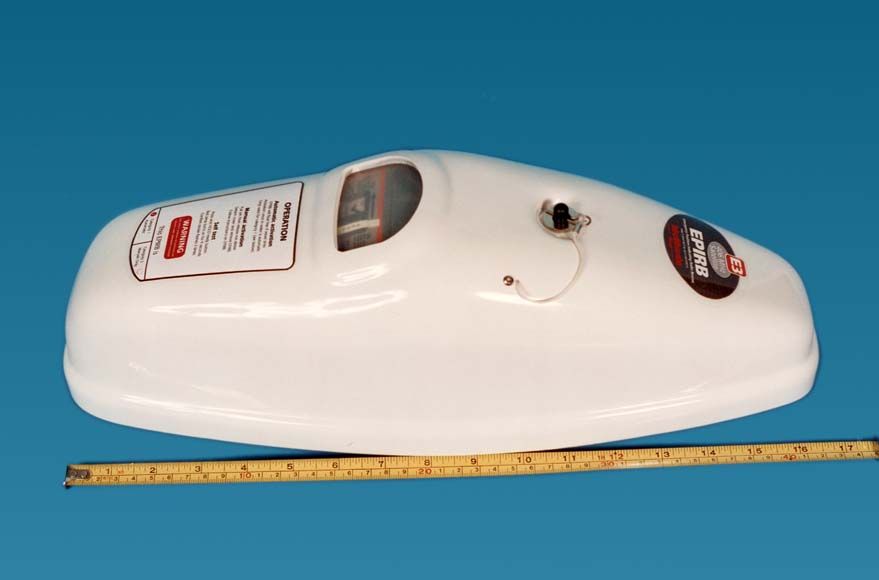
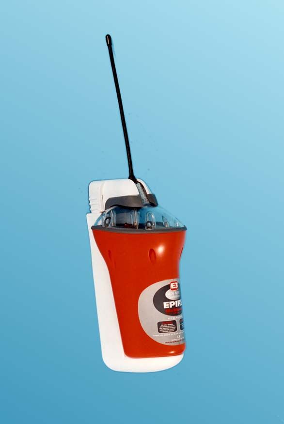
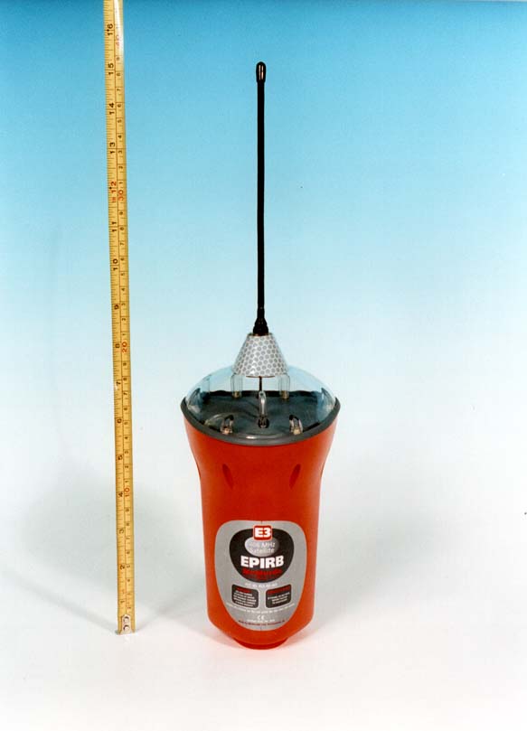
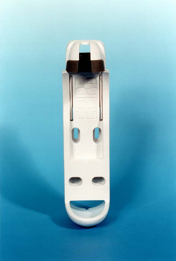
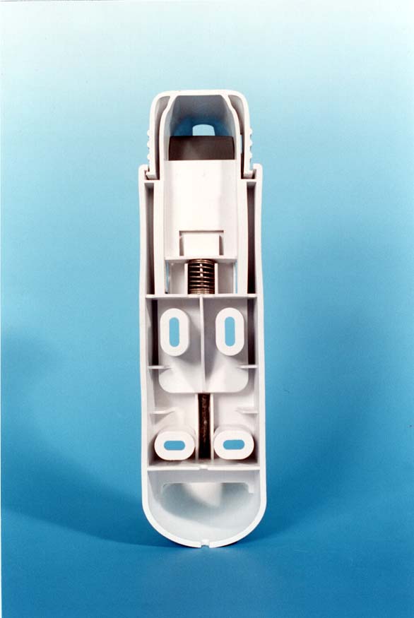
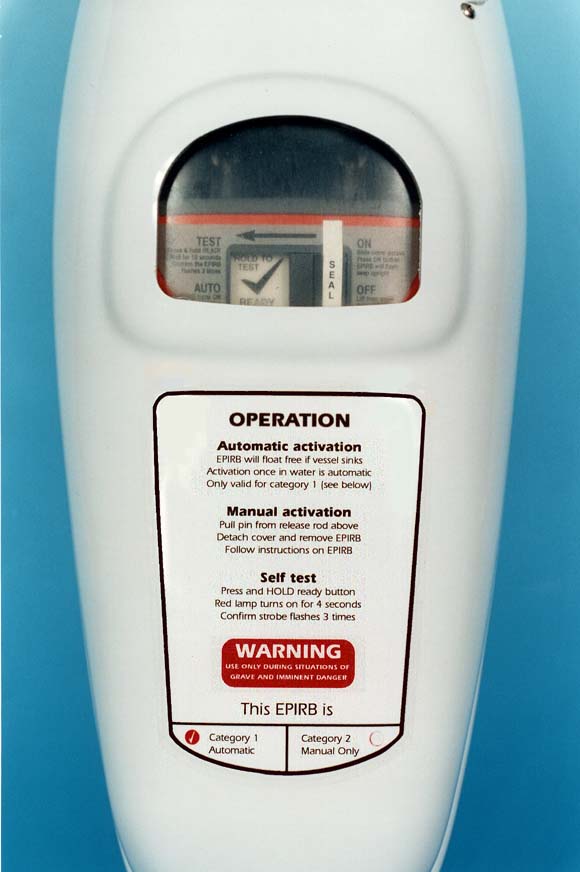
406 MHz Satellite OWNERS MANUAL sos 3 4 2 2 1 1 5 1 1. PURPOSE An Emergency Position Indicating Radio Beacon (EPIRB) is used to alert search and rescue services in the event of an emergency. It does this by transmitting a coded message on the 406 MHz distress frequency. This message is relayed via satellite and earth station to the nearest rescue co-ordination centre. The McMurdo E3 works with the Cospas-Sarsat polar orbiting satellite system which provides true global coverage. The system has an alert delay of typically 45 minutes dependant on when the satellites come into view on the horizon. The satellite can determine the position of your E3 to within 5km (3 miles) and the coded message identifies the exact vessel to which the E3 was registered. This information allows the rescue services to eliminate false alerts and launch an appropriate rescue. The E3 also has a secondary distress transmitter. This transmits on 121.5 MHz and is used for “homing” purposes. When the rescue services get close, this allows them to direction find on the signal. To cater for searches at night, the E3 has a bright flashing light that aids final visual location. S E A L READY TEST PRESS TO Antenna Strobe Red lamp Program point Sea contacts Lanyard ON button under here READY button Battery expiry date 2 2. DESCRIPTION The E3 is a powerful self-contained distress transmitter. It is powered by a light weight Lithium battery that has a replacement interval of 5 years. An EPIRB is intended to be a one-shot device, once activated it can operate for 48 hours. It operates best while floating in water, but it can also be operated while onboard. Refering to the previous figure, the key components of your E3 are as follows. AntennaThis is a flexible whip. It must be near vertical when operating. If the antenna gets bent, gently straighten it out. Strobe lightThis is the glass U-tube visible through the clear lens dome. When the E3 is activated this will flash every few seconds. Red lampVisible through the clear lens dome at the rear of the E3. This stays on or flashes to show you which mode you are in. Program pointA dimple in the clear dome, through which your supplier can optically input the coded message unique to your E3. You must register the coded message with local authorities. READY buttonPress this key once to de-activate the E3. Hold it down to run the built-in self-test, which checks basic operation. ON buttonPress this key to manually activate the E3. The key is protected by a sliding door, which is fitted with a tamper seal. Sea switchThe two screw heads below the keys are sea switch contacts. Submerge these in water to automatically activate the E3. LanyardPull the lanyard spool down to free it. Use the cord to tether the E3 to a survival craft. Never tie the E3 to your vessel. 2.1 Wall bracket If you purchased the manually activated version (E3m), this is normally supplied with a wall mounting bracket (see section 6). The bracket is made from white plastic so it will not rust. Its top section is sprung loaded, so that one simple squeeze will quickly release the E3 allowing it to be carried to a liferaft. The wall bracket should be sited in plain view near an emergency exit. This bracket is more than just a stowage point, it contains a magnet which disarms the E3’s sea switch. If you do not stow the E3 in its bracket, there is a risk of the E3 activating if it gets wet. 2.2 Float-free enclosure If you purchased the automatically activated version (E3a), also known as the “float- free” version, then your E3 is supplied in a plastic enclosure (see section 7). This is much more than just a protective housing, it contains a sprung loaded lever which automatically pushes the enclosure lid off and releases the E3 if your vessel sinks. This automatic ejection is controlled by a device called a Hydrostatic Release Unit (HRU). If the enclosure is submerged then before it reaches 4 metres (13 feet) deep 3 the HRU cuts a plastic rod that holds back the spring and the lid is ejected, releasing the EPIRB which floats to the surface and switches on automatically. The diagram below illustrates the automatic release sequence. 1) As the vessel sinks, the enclosure fills with water. The HRU contains a blade which is released due to water pressure acting on a diaphragm. Before it reaches a depth of 4 metres, the HRU will operate and cut the plastic rod, releasing the coil spring. 2) The spring pushes the E3 and the enclosure lid outwards. As the lid pivots off it disengages from the screw head that helped hold it in place. The lid is weighted so it rolls over and falls away. 3) As the E3 floats away from the lid, it moves out of range of the magnet. Once away from the magnet its sea switch becomes armed. 4) The sea switch activates. The EPIRB then floats on the surface with its strobe light flashing. After 50 seconds it makes its first distress transmission. If you need to manually activate your E3, it can be freed from the enclosure simply by pulling out the R-shaped retaining pin and removing the lid. 2.3 Manual E3 in enclosure Customers who need to mount their E3 in an exposed position can select the protective enclosure without an HRU fitted (E3c). This means that the E3 will not float free if your vessel sinks. This is known as a category 2 EPIRB. You can tell which enclosure you have by reading the category from the front of the enclosure... E3aCategory 1HRU fittedAutomatic float-free E3cCategory 2No HRU fittedWill not float free H R U 1) HRU cuts rod 2) Lid ejects 4) sea switch activates 3) EPIRB arms once away from magnet Magnet 4 READY HOLD TO TEST ON 3. CONTROLS 3.1 ON button This is hidden behind a sliding door, which protects it from accidental activation. The sliding door has a tamper seal to show if the E3 has been activated before. The E3 can be manually activated by sliding the door to the left (breaking the seal) and then momentarily pressing the ON button. When activated the E3 will start to flash immed…
Text truncated - open the document above for the full version.
Block Diagram
BLOCK DIAGRAM OF E3 ELECTRONICS BATTERY SWITCH CONTROL LOGIC ON READY SEA SWITCH 5V REGULATOR TEST OUTPUT LED DRIVER LED MICRO- CONTROLLER STROBE CIRCUIT XENON TUBE 121.5MHz OSCILLATOR BUFFER PA MODULATION PHASE MODULATOR OCXO BUFFERPA PHASE LOCKED LOOP VCO PA ON/OFF CONTROL MODULATION DIPLEXER ATU DETECTOR DIVISION RATIO OCXO REGULATOR 5V 121.5MHz OSCILLATOR REGULATOR 3V7 ON/OFF VCO/PLL REGULATOR 3V5 MICROCONTROLLER STROBE AND 406 PA 121 PA ANTENNA REED SWITCH 12.688MHz 4MHz CLOCK
Cover Letter(s)
McMurdo Limited, Rodney Road, Fratton, Portsmouth, Hampshire PO4 8SG Telephone Portsmouth (01705) 775044, Facsimile (01705) 819087 BS EN ISO 9001 ApprovalCECC and CAA Approval Telephone: +44 1705 77501510 th of March 1999 e-mail: [email protected] Reference: Form 731 confirmation number EA93430 FCC ID: KLS82-001 Dear Ms Taube, as per our e-mail communications, I wish to confirm that the 731 form we submitted on Friday the 5 th of March 1999, is in error. We asked for compliance with FCC rules parts 80.1061. This should be amended to request compliance with FCC rules parts 80.1101 (c) (5). Your help in resoving this matter is much appreciated. Best regards, Richard Read ( for McMurdo Ltd).
Cover Letter(s)
RTCM Float free test report The PDF version of the test report is over 11Mb in size! The servers have re-set twice whilst trying to send the full version. I have now split the report into five files; a text file and four photo files which I am submitting individually. Richard Read (for McMurdo Ltd)
Cover Letter(s)
Page 1 of 106/26/01 Ref: EPIRB 121MHz homer output power. We are happy for you to state that the 121MHz homer output power is 25mW on the approval certificate, with the understanding that the RTCM ERP tolerance will allow operation at 50 mW. In addition, our 731 form requests approval to 80.1101 (c) (5) which is full GMDSS approval. We know you have a letter from the USCG stating that the manual version is acceptable. We assume that you have now received a second letter from the USCG confirming their approval of our float-free version. We are expecting you to issue a certificate covering full GMDSS use. If this is the case, then proceed and ignore this paragraph. If not, then please wait for the letter from Bob Markle at the USCG. He was promising to process our float-free report last week. Richard Read ( for McMurdo Ltd.)
ID Label/Location Info
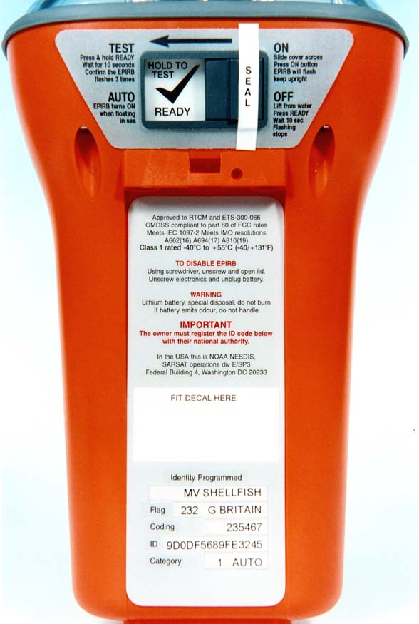
Page 1 of 12 E3 AND VARIANT MANUAL AND FLOAT-FREE LABELS This document details the labels fitted to the E3 EPIRB and it’s variants. In most instances the images are scanned labels, as fitted to units, but are not to scale. In all other cases drawings of the labels are included where the labels are produced in-house. Details of the label placement may be inferred by reference to the EPIRB photos in the ‘FCC photo’s’ folder with this submission. Page 2 Drawing of EPIRB fitting label. Page 3 Drawing of barcode label. Page 4 Drawing of expiry label. Page 5 and 6 Scanned images of float-free housing labels. Page 6 Scanned images of manual bracket label. Page 7 Scanned images of E3 variant front label. Page 8 Scanned images of SOS variant front label. Page 9 Scanned images of SEA variant front label. Page 10 Scanned images of rear switch labels. Page 11 Scanned images of rear information labels. Page 12 Scanned images of operating placards Page 2 of 12 E 50 130 123-11-98 ISSUE CHANGE No DATE TOLERANCES UNLESS OTHERWISE STATED WHOLE No 1 DEC PLACE 2 DEC PLACES ANGULAR DIMS DRILLED HOLES ALL DIMS IN mm CHECKED APP'D DRAWN BS308 3RD ANGLE PROJECTION SCALE McMurdo Ltd PORTSMOUTH - HAMPSHIRE - ENGLAND TITLE DRAWING No SHEET OF MATERIALFINISH 1:1 JVN LABEL FITTING 82-222D 1 1 0.5 1) VINYL FILM SCREEN PRINTED TO FRONT 2) BLACK GRAPHICS ON CLEAR BACKGROUND NOTES 5) FOR ARTWORK USE MS-WORD / MS-DRAW FILE CALLED --- 82-222Liss1.doc C1366 2 3 1 82-222D iss 1 FASCAL 940 CLEAR VINYL 3) ADHESIVE AS SUPPLIED ON MATERIAL 4) ADHESIVE TO HAVE PEELABLE BACKING Page 3 of 12 Barcode here EAN-13 5 035963 000045 McMurdo Ltd 82-011A E3 Manual Battery Expiry VESSEL ISSUE CHANGE No DATE TOLERANCES UNLESS OTHERWISE STATED WHOLE No 1 DEC PLACE 2 DEC PLACES ANGULAR DIMS DRILLED HOLES ALL DIMS IN mm CHECKED APP'D DRAWN BS308 3RD ANGLE PROJECTION SCALE McMurdo Ltd PORTSMOUTH - HAMPSHIRE - ENGLAND TITLE DRAWING No SHEET OF MATERIALFINISH JT 1:1 1 1 82-149D LABEL BARCODE BLACK TEXT ON CLEAR BACKGROUNDFASCAL 940 CLEAR VINYL or Equiv. ADHESIVE BACKING TO BS5609LETTERING UV STABLE A25-11-98 73 62 2.0 VARIANTASSYBRANDTITLE BARCODE 82-149-001 82-001A McME3 AUTO5 035963 000014 82-149-004 82-004A PWSSSOS 406 AUTO5 035963 000021 82-149-006 82-006A SEASEA 406 AUTO5 035963 000038 82-149-011 82-011A McME3 MANUAL5 035963 000045 82-149-014 82-014A PWSSSOS 406 MANUAL 5 035963 000052 82-149-016 82-016A SEASEA 406 MANUAL 5 035963 000069 82-149-021 82-021A McME3 CASED5 035963 000076 82-149-024 82-024A PWSSSOS 406 CASED5 035963 000083 82-149-026 82-026A SEASEA 406 CASED5 035963 000090 82-149-031 82-031A McME3 CASE 5 035963 000106 82-149-034 82-034A PWSSSOS 406 CASE5 035963 000113 82-149-036 82-036A SEASEA 406 CASE5 035963 000120 VARIANT TABLE PROGRAMMED INFORMATION NOTES VESSEL NAME MAY BE LEFT EMPTY (IF UNKNOWN) PRODUCT TITLE SEE VARIANT TABLE EPIRB ASSY No SEE VARIANT TABLE NOTES 1) USE BRADY LABEL PRINTER 2) SELECT LABEL FROM LIST 3) PRINT LABEL FITTED WITH 3" CLEAR MAT'L TRIM TO BLACK BORDER UNIT INFORMATION SERIAL No : eg 52-0001 BATTERY EXPIRY : JUN 2004 Programmed Unprogrammed Serial No MUST TICK EITHER PROG OR UNPROG. 1 C1419 28-01-99 Page 4 of 12 Do NOT paintDo NOT use cleaning agents Replace HRU Replace battery Vessel Flag Coding ID EXPIRY Class 1 rated -40 to +55 C -40 to +131 F Compass safe distance 1m (3') FCC ID: KLS-82-001 S/N Lithium battery ISSUE CHANGE No DATE TOLERANCES UNLESS OTHERWISE STATED WHOLE No 1 DEC PLACE 2 DEC PLACES ANGULAR DIMS DRILLED HOLES ALL DIMS IN mm CHECKED APP'D DRAWN BS308 3RD ANGLE PROJECTION SCALE McMurdo Ltd PORTSMOUTH - HAMPSHIRE - ENGLAND TITLE DRAWING No SHEET OF MATERIALFINISH 2.0 1 1 82-214D LABEL EXPIRY JVN 1:1 A25-11-98 FASCAL 940 CLEAR VINYL or Equiv. ADHESIVE BACKING TO BS5609 BLACK TEXT ON CLEAR BACKGROUND LETTERING UV STABLE 110 35 NOTES 1) PRODUCE ON BRADY LABEL PRINTER 2) USE 3" WIDE CLEAR MATERIAL 6) PRINT LABEL 4) SELECT LABEL FROM LIST 3) YOU WILL NEED EPROG3 PACKING DATA BATTERY EXPIRY DATE --- FORMAT : JUN 2004 5) ENTER DATA SHOWN USING BLADE TRIM TO BLACK BORDER ALWAYS BLANK USUALLY BLANK UNLESS VESSEL NAME KNOWN Page 5 of 12 EPIRB FLOAT FREE HOUSING LABELS E3 VARIANT LABEL SOS VARIANT LABEL SEA VARIANT LABEL Page 6 of 12 COMMON INFORMATION LABEL MANUAL BRACKET LABEL Page 7 of 12 EPIRB BODY FRONT LABELS E3 VARIANT FRONT LABEL Page 8 of 12 SOS VARIANT FRONT LABEL Page 9 of 12 SEA VARIANT FRONT LABEL Page 10 of 12 EPIRB BODY REAR LABELS E3 AND SEA VARIANT SWITCH LABEL SOS VARIANT SWITCH LABEL Page 11 of 12 E3 AND SEA VARIANT REAR LABEL SOS VARIANT REAR LABEL Page 12 of 12 EPIRB PLACARDS AUTO PLACARD MANUAL PLACARD
Operational Description
E3/ Rescue 406 EPIRB Technical Specification General Approved toCOSPAS-SARSAT T.001 class1 RTCM SC110-STD Version 2 class 1 ETS 300 066 IEC 1097-2 Complies withEN 60945 Part 80 of FCC regulations Operating temperature range-40ºC to +55ºC Storage temperature range-50ºC to +70ºC Operational life48 hours minimum at -40ºC Battery type9V lithium sulphur dioxide Battery expiry6 years from date of manufacture Electrical 406.025MHz transmitter Frequency406.025MHz + 5KHz Output power5W + 2dB Data encodingBi-phase L ModulationPhase modulation: 1.1 rads + 0.1 rads Transmission time440ms + 1% Repetition period50 secs + 2.5 secs 121.5MHz homing transmitter Frequency121.5MHz + 3KHz Output power50mW + 3dB PERP Transmit duty cycleContinuous Modulation format3K20A3X Modulation frequency sweep1300Hz to 350Hz Modulation duty cycle38% + 5% Sweep repetition rate3Hz + 1Hz Sweep directionProgrammable UP or DOWN Antenna TypeFlexible, vertical whip CharacteristicsVertically polarised, omni-directional Optical Homer TypeXenon discharge tube Flash rate20 to 23 flashes per minute Light output> 0.75 candela over ≥75% of the horizontal plane External Interfaces Programming interfaceInfra-red link via RS232 port on a PC. Manual activationSealed membrane switch. Protected by sliding cover. Automatic activationSea water switch contacts. Activation within 5 seconds of immersion. Self testSealed membrane switch. Press and hold to activate self test. Confirmation of successful self test by 3 flashes of strobe light. Physical characteristics Weight730 grams nominal Height210mm to base of antenna. Width110.5mm at maximum
Operational Description
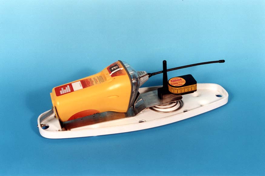
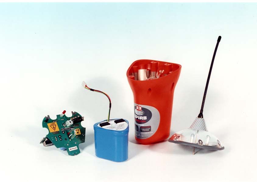
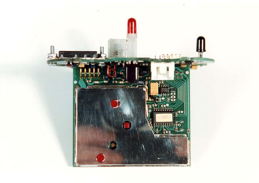
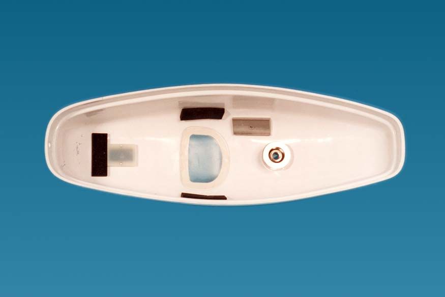
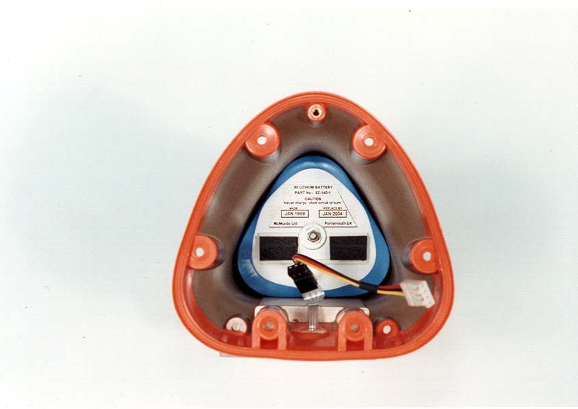
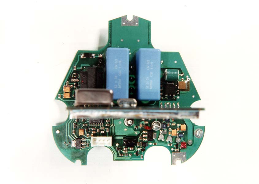
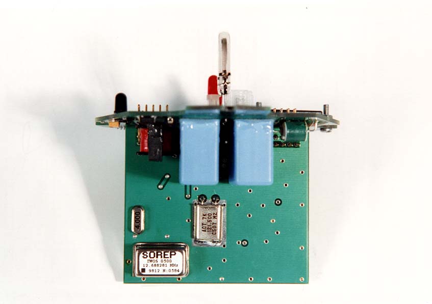
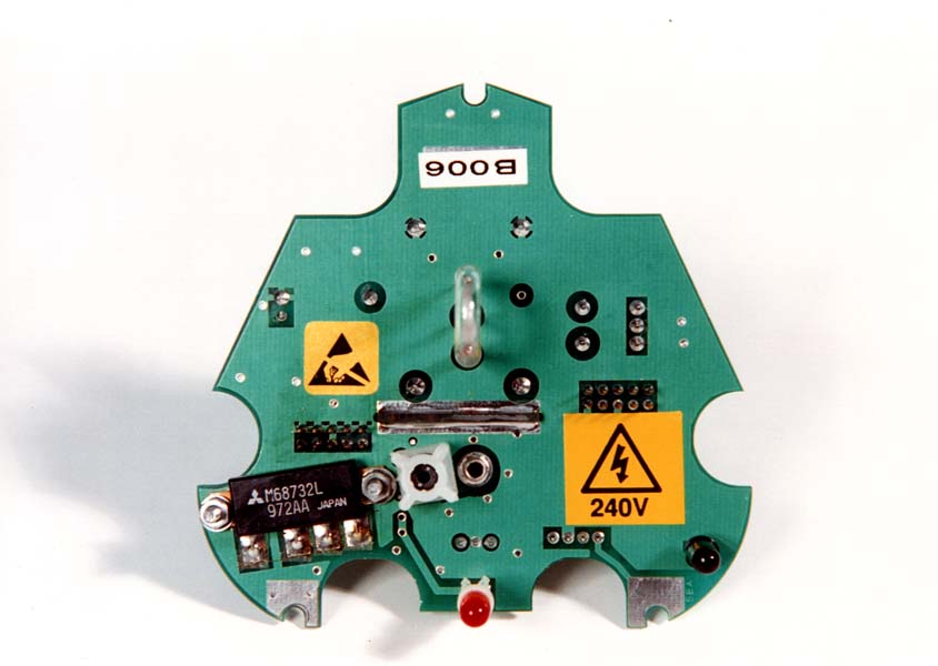
COMMERCIAL IN CONFIDENCE COMMERCIAL IN CONFIDENCE TECHNICAL DESCRIPTION OF THE E3 / RESCUE 406 EPIRB The E3 is a 406MHz float free satellite EPIRB with a built in 121.5MHz homing beacon and is used to locate a vessel or life raft in distress. When activated, encoded data is transmitted, enabling identification of the vessel and its position to better than 3Km. The EPIRB comes complete with an automatic release mechanism. BEACON DESCRIPTION The E3 consists of two mouldings, a transparent top dome made from Polycarbonate and a main body made from a Polycarbonate/ABS thermoplastic mix. The main body is internally sprayed with a conductive coating to achieve good EMC performance. The two mouldings are screwed together. A gasket made from Sarlink, which is a thermoplastic elastomer, is used to provide a waterproof seal. The bottom molding contains the battery pack and a counter balance weight to give good buoyancy characteristics. On the rear of the moulding are two seawater switch contacts and two membrane switches. One membrane switch is labeled HOLD TO TEST/READY and the other is labeled ON. The ON switch is protected against inadvertent use by a plastic cover fitted with a tamper seal. The EPIRB cannot be manually operated unless the tamper seal is removed and the plastic cover slid across to the left of the moulding. The bottom moulding also houses the EPIRB electronics, which are contained on two printed circuit boards, configured in a ‘T’. The top dome is transparent so that Xenon tube is clearly visible. The top dome also provides the mechanical fixing for the 406MHz/121.5MHz antenna. A recess in the moulding allows for aligning a light pen for infra-red data programming. The E3 is programmed via an infra-red data link. This means that a vessel’s unique identity number can be programmed into the E3 via a RS232 interface. This data is then permanently stored in the EPIRB. This system enables swift and easy programming of the EPIRB without having to break the watertight seal. COMMERCIAL IN CONFIDENCE COMMERCIAL IN CONFIDENCE RELEASE MECHANISM The E3 is protected in a ‘floatfree’ two-part housing which provides safe storage for the EPIRB until it is required for use. The two-part housing is made from Acrylate Styrene Arylonitrile, which is a thermoplastic material. The bottom half contains the release mechanism and is designed to be bolted to a bulkhead. The release mechanism consists of a stainless steel bracket to support the EPIRB, a spring and a hydrostatic release unit. The bracket containing the EPIRB compresses the spring, and is held in place by an acetal copolymer rod that passes through the hydrostatic release and is secured using a circlip at the base of the bottom housing. The top and bottom housings are then secured together with the aid of an R clip passed through the acetal copolymer rod which protrudes through the top housing. The hydrostatic release will operate at a depth of 1.5m-4m. Once activated the hydrostatic release cuts the acetal copolymer rod. This releases the spring and forces the two halves apart allowing the EPIRB to float to the surface. COMMERCIAL IN CONFIDENCE COMMERCIAL IN CONFIDENCE E3/ RESCUE 406 EPIRB TECHNICAL SPECIFICATION GENERAL Approved toCOSPAS-SARSAT T.001 class1 RTCM SC110-STD Version 2 class 1 ETS 300 066 IEC 1097-2 Complies withEN 60945 Part 80 of FCC regulations Operating temperature range-40ºC to +55ºC Storage temperature range-50ºC to +70ºC Operational life48 hours minimum at -40ºC Battery type9V lithium sulphur dioxide Battery expiry6 years from date of manufacture ELECTRICAL 406.025MHz transmitter Frequency406.025MHz + 5KHz Output power5W + 2dB Data encodingBi-phase L ModulationPhase modulation: 1.1 rads + 0.1 rads Transmission time440ms + 1% Repetition period50 secs + 2.5 secs 121.5MHz homing transmitter Frequency121.5MHz + 3KHz Output power50mW + 3dB PERP Transmit duty cycleContinuous Modulation format3K20A3X Modulation frequency sweep1300Hz to 350Hz Modulation duty cycle38% + 5% Sweep repetition rate3Hz + 1Hz Sweep directionProgrammable UP or DOWN Antenna TypeFlexible, vertical whip CharacteristicsVertically polarised, omni-directional COMMERCIAL IN CONFIDENCE COMMERCIAL IN CONFIDENCE Optical Homer TypeXenon discharge tube Flash rate20 to 23 flashes per minute Light output> 0.75 candela over ≥75% of the horizontal plane EXTERNAL INTERFACES Programming interfaceInfra-red link via RS232 port on a PC. Manual activationSealed membrane switch. Protected by sliding cover. Automatic activationSea water switch contacts. Activation within 5 seconds of immersion. Self testSealed membrane switch. Press and hold to activate self test. Confirmation of successful self test by 3 flashes of strobe light. PHYSICAL CHARACTERISTICS Weight730 grams nominal Height210mm to base of antenna. Width110.5mm at maximum COMMERCIAL IN CONFIDENCE COMMERCIAL IN CONFIDENCE CIRCUIT DESCRIPTION The E3 EPIRB is powered by three 3V Lithium Sulphur Dioxide batteries connected in series, which gives a nominal voltage of 8.4V. The battery pack is protected by a 2A fuse. The battery pack is designed to last for at least 48hours at –40ºC and be capable of supplying 1.8A pulses every 50 seconds. Refer to drawing 82-100C ACTIVATION The EPIRB is activated by energising Q13, this can be done by either pressing the ON membrane switch, the READY membrane switch, or via the seawater switch contacts. The seawater switch operates when the resistance across the contacts is less than 60K ohms. This allows IC9d output to switch high. IC9c will switch low after a delay of 2 seconds due to the time constant formed by R65 and C55. This enables D4 to conduct and Q13 to turn on. In this state, the unit may only be turned off by removal from water. C55 will discharge through R78 causing Q10 to switch off after a delay of 6 seconds. The combination of IC9a and IC9b form a set-reset bistable. When the ON membrane switch is pressed, the output of IC9b switches high and is latched by IC9c switch…
Text truncated - open the document above for the full version.
Schematics
BLOCK DIAGRAM OF E3 ELECTRONICS BATTERY SWITCH CONTROL LOGIC ON READY SEA SWITCH 5V REGULATOR TEST OUTPUT LED DRIVER LED MICRO- CONTROLLER STROBE CIRCUIT XENON TUBE 121.5MHz OSCILLATOR BUFFER PA MODULATION PHASE MODULATOR OCXO BUFFERPA PHASE LOCKED LOOP VCO PA ON/OFF CONTROL MODULATION DIPLEXER ATU DETECTOR DIVISION RATIO OCXO REGULATOR 5V 121.5MHz OSCILLATOR REGULATOR 3V7 ON/OFF VCO/PLL REGULATOR 3V5 MICROCONTROLLER STROBE AND 406 PA 121 PA ANTENNA REED SWITCH 12.688MHz 4MHz CLOCK
Test Report
EMC Test Report The attached PDF format file, is derived from scanned extracts from the E3 EMC test report. The EMC evaluation was carried out by personnel at DERA Fraser in Portsmouth. This is a UKAS accredited facility and is also recognised by the USCG. This report covered testing to BS EN60945 and FCC requirement 47 CFR Ch 1. Only the FCC tests are reproduced.
Test Report
1 FCC submission (additional tests) This report details the results of measurements made at McMurdo Ltd, to satisfy the relevant items listed in CFR47 section 80.1061b and 2.985-2.997. These items are not generally covered in the main RTCM test report. Test equipment 1.Spectrum analyserAdvantest R3371 2.Frequency counterPhilips PM6680 3.Temperature chamberMontford BMC24 4.Power meterHewlett Packard 437B + 8482B Power head 5.Attenuator N-type 50Ω in-line attenuator 30dB 6.ThermometerComark 2001 Test Frequency The unit under test was fitted with a 121.65MHz crystal to avoid interference. 121.5MHz homer --- Compliance with 80.1061b. Modulation characteristics. Testing was carried out in accordance with “Subpart N” the FCC procedure for testing Class A,B and S EPIRBS. Characteristics121.65MHzLimit Sweep Start Frequency1307Hz1600Hz Sweep stop frequency348Hz300Hz Sweep frequency range959>700 Sweep repetition3.09Hz2Hz-4Hz Modulation factor0.910.85-1.0 Modulation duty cycle35%-41.8%33%-55% 2 Plots 1&2 shown below are to determine the duty cycle at 1KHz. 1. 2. 3 Plots 3&4 below to determine the duty cycle at 1.3KHz. 3. 4. 4 Plots 5&6 below to determine the duty-cycle at 348Hz. 5. 6. 5 Signal Enhancement The mean power correction for duty cycle made use of the highest duty cycle as this gave the worst results for carrier content. Characteristic121.65MHz Highest duty cycle41.83% 10log (Duty) factor-3.785 Total mean power18.422dBm Carrier power10.225dBm dBc-dBt-4.411 Carrier content36.21% Compliance with 2.985 : RF power output The Hewlett Packard 437B power meter was to measure the RF power at both frequencies... Power at 121.65MHz = 19.5dBm Power at 406.025MHz = 36.81 dB Compliance with 2.987 : Modulation characteristics Refer to the RTCM report, reference DERA/SS/WI/RTCM/R-TT7/98-1.0. The report covers both the 406.025MHz and 121.5MHz modulation. Compliance with 2.989 : Occupied bandwidth. The spectrum analyser's built in maths function was used for measurement. The power limit being set to 99% as required by FCC rules. The analyser settings for the 121.65MHz and 406.025MHz frequencies are shown on the plots below. 6 Characteristic121.65MHz406.025MHz Occupied bandwidth10.21KHz5.64KHz Compliance to 2.991 : Spurious emissions at antenna terminals Below shows the emission spectrum for the 406.025MHz transmission. It can be clearly seen that the only spurious are harmonics of 406.025MHz which are more than 38dB below the wanted signal. The plot overleaf shows the spectrum for the 121.5MHz transmission. It can be clearly seen that the only spurious are harmonics of 121.5MHz, which are more than 39dB below the wanted signal. These are of course significantly attenuated by the antenna characteristics. 7 Compliance with 2.993 : Field strength of spurious radiation. Please refer to the DERA EMC test report (DERA/SSW1/R/EMC/TT – 07/98/1.0) attached to this submission. Compliance 2.995 : Frequency stability. Frequency vs. temperature Conducted as per FCC procedure. New battery fitted. Soak time 1 hour per step. Characteristic121.65MHz406.025MHzLimit Initial freq accuracy+5.1 ppm+2.16 ppm+/-50ppm Freq. accuracy over temp+7.2/-11.9 ppm+1.86/+2.23 ppm+/-50 ppm Temp ( °C) Freq. (MHz)Error (ppm)Freq. (MHz)Error (ppm) -40121.648556-11.9406.0257561.86 -30121.649415-4.81406.0257801.92 -20121.6500750.62406.0258122.00 -10121.6504813.96406.0258322.05 0121.6506755.56406.0258472.09 10121.6507336.03406.0258642.13 20121.6507075.82406.0258812.17 30121.6506555.47406.0258852.18 40121.6506815.61406.0258902.19 50121.6508156.71406.0259112.24 55121.6509387.72406.0259072.23 8 121.65 MHz -12 -11 -10 -9 -8 -7 -6 -5 -4 -3 -2 -1 0 1 2 3 4 5 6 7 8 -40-30-20-10 0 102030405060 Temperature degC Freq error (ppm) Compliance with 2.997 : Frequency spectrum to be investigated. Please refer to DERA EMC test report attached. 406 MHz 1.5 1.6 1.7 1.8 1.9 2 2.1 2.2 2.3 -40-30-20-100102030405060 Temperature deg C Freq error (ppm)
Test Report
Page 107/03/01 USCG/ RTCM approval The data required by the USCG is currently under review by Robert Markle. As soon as we get a decision, this information will be forwarded as an additional exhibit. Richard Read (for McMurdo Ltd).
Contact Information
Applicant
Erwan Thomas(Certification and hardware engineer)
Technical Contact
Non-Technical Contact
McMurdo LtdSteve Metcalf
[email protected]+44 1705 775042
Technical Specifications
| # | Rule Parts | Frequency Range | Power Output | Emission | Tolerance |
|---|---|---|---|---|---|
| 2 | 80.1101(c)(5) | 406.025 MHz - 406.025 MHz | 5 W | 16K0G1D | 5000 Hz |
Other Applications from Orolia Ltd

KLS-Z502
Apr 19, 2012AIS-MSLD
Equipment Class
AIS - Automatic Identification Systems
KLS-Z501
Apr 19, 2012AIS-MSLD
Equipment Class
AIS - Automatic Identification Systems
KLS-G5-2
Jul 10, 2011McMurdo Smartfind Plus G5, Sailor SGE406-II, Simrad EG50
Equipment Class
GEP - 406 MHz EPIRB
KLS-E5-2
Jul 10, 2011McMurdo Smartfind E5, Kannad Marine Automatic EPIRB, Kannad Marine Manual EPIRB, Sailor SE406-II, Simrad EP50
Equipment Class
GEP - 406 MHz EPIRB
KLS-PLB-4-GPS
Apr 05, 2011Fastfind MaxG, Safelink Pro, XS-ER GPS
Equipment Class
PLB - Personal Locator Beacons